Originally published as an Oracle tutorial on Oracle Docs. Part 3 of 5 in the NAT on DRG series.
Introduction
The most painful place to find an IP overlap is between Oracle Cloud Infrastructure (OCI) and an on-premises network. Inside OCI you could still re-create a VCN with a different CIDR. An on-premises network with thousands of devices is not going to be re-addressed because a cloud project picked the same 10.0.0.0/16. The same problem appears when you connect a partner or a customer over a VPN and have no say in their address plan.
NAT on DRG lets the Dynamic Routing Gateway (DRG) translate the addresses on the Site-to-Site VPN itself. A DRG NAT policy is associated with the IPSec tunnel attachments, and each side is presented to the other under a unique “shadow” CIDR:
| Side | Real subnet CIDR | Shadow CIDR seen by the other side |
|---|---|---|
OCI VCN uc3-vcn-oci |
10.0.1.0/24 |
192.168.10.0/24 |
| On-premises LAN | 10.0.1.0/24 |
192.168.20.0/24 |
An instance in OCI reaches an on-premises host on 192.168.20.x, and an on-premises host reaches OCI on 192.168.10.x. The on-premises router needs no NAT configuration at all: all the translation is done by the DRG.
This part has more moving pieces than the earlier ones, because a VPN brings two things of its own:
- The encryption domain. A policy-based IPSec tunnel only carries traffic that matches its traffic selectors. Those selectors must match the addresses that are actually on the wire, and that is after the DRG has translated them.
- Routing towards the tunnel. A static route in a DRG route table cannot point to an IPSec tunnel. The DRG has to learn the route to the on-premises shadow CIDR dynamically from the tunnel. This tutorial shows how to make that happen.
For this tutorial the on-premises network is simulated with a second VCN in another region, with a Libreswan instance as the customer-premises equipment (CPE). Everything on the OCI side is exactly what you would configure against a real on-premises router.
Other Use Cases
This tutorial is part of a series of five. Every part solves a different overlap scenario with the same building blocks.
- Part 1: NAT on DRG Part 1: Overlapping CIDRs between two local VCNs
- Part 2: NAT on DRG Part 2: Overlapping CIDRs between multiple remote VCNs
- Part 3 (this article): NAT on DRG Part 3: Overlapping CIDRs between OCI and On-Premises
- Part 4: NAT on DRG Part 4: Shared services VCN
- Part 5: NAT on DRG Part 5: Overlapping CIDRs between OCI and On-Premises with BGP
Diagram
Overlapping IPs between VCN subnet CIDR and on-premises or remote network with stateless 1:1 NAT on DRG
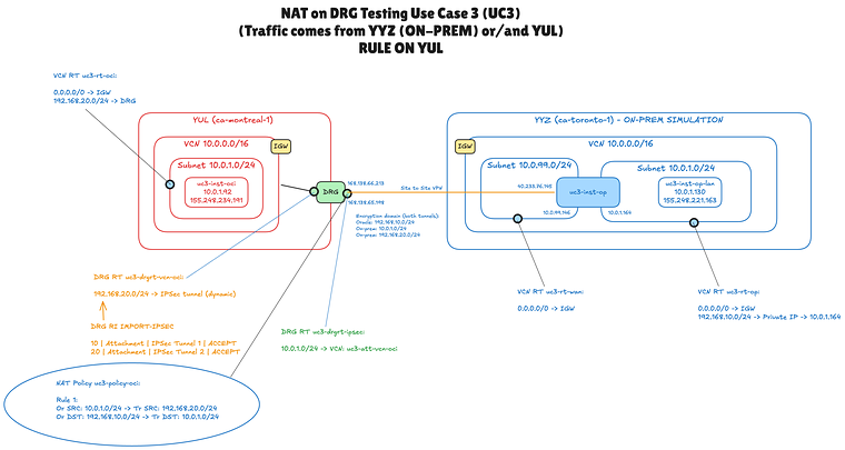
The diagram shows every object you configure in this tutorial:
- The OCI side in the Canada Southeast (Montreal) region: the VCN
uc3-vcn-oci(10.0.0.0/16) with the subnet10.0.1.0/24and the test instanceuc3-inst-oci(10.0.1.92). - The simulated on-premises side in the Canada Southeast (Toronto) region: a VCN with a WAN subnet
10.0.99.0/24and a LAN subnet10.0.1.0/24. The Libreswan instanceuc3-inst-ophas a leg in both subnets (10.0.99.146and10.0.1.164), anduc3-inst-op-lan(10.0.1.130) is a host on the LAN. - One DRG with a VCN attachment and a Site-to-Site VPN with two IPSec tunnels to the public IP address of the Libreswan instance.
- The encryption domain of the tunnels (small blue text below the VPN line):
192.168.10.0/24on the Oracle side, and10.0.1.0/24plus192.168.20.0/24on the on-premises side. - Two DRG route tables:
uc3-drgrt-vcn-oci(orange text) for the VCN attachment, which learns the route192.168.20.0/24from the tunnels through the import route distributionIMPORT-IPSEC, anduc3-drgrt-ipsec(green text) for the IPSec tunnel attachments, with a static route to the VCN. - One DRG NAT policy (the ellipse) with a single rule, associated with both IPSec tunnel attachments.
Prerequisites
- An OCI tenancy that is subscribed to two regions, and a compartment in which you are allowed to manage networking resources (VCNs, DRGs, Site-to-Site VPN, DRG route tables and DRG NAT policies) and compute instances.
- The networks on both sides already exist. This tutorial does not create them. In the lab they are the VCN
uc3-vcn-ociand the VCNuc3-vcn-onpremthat simulates the on-premises network, each with its subnets, an internet gateway and route tables that send0.0.0.0/0to the internet gateway. Steps 01 and 02 walk through this starting point. - A DRG that supports NAT. NAT on DRG is not available on legacy (V1) DRGs, and not on DRGs that have disintermediation, high-throughput mode or route unification enabled. A newly created DRG works.
- An on-premises router that supports policy-based IPSec, or the simulated one from this tutorial: an Oracle Linux instance with Libreswan, a public IP address and a second VNIC in the LAN subnet.
- Compute instances to test with. In this tutorial they are called
uc3-inst-oci(10.0.1.92) on the OCI side anduc3-inst-op-lan(10.0.1.130) on the on-premises side. - An SSH key pair for the instances, and the public IP address you connect from (to allow it in the security lists).
- Basic knowledge of Site-to-Site VPN, VCN route tables and DRG route tables. If NAT on DRG is new to you, start with NAT on DRG Part 1: Overlapping CIDRs between two local VCNs.
Steps
- STEP 01: Review the VCN on the OCI side
- STEP 02: Review the simulated on-premises network
- STEP 03: Configure the security lists
- STEP 04: Configure the routing on the on-premises side
- STEP 05: Create the DRG and attach the VCN
- STEP 06: Create the Site-to-Site VPN
- STEP 07: Configure the encryption domain of the tunnels
- STEP 08: Configure Libreswan on the on-premises side
- STEP 09: Configure the DRG route tables
- STEP 10: Configure the VCN route table on the OCI side
- STEP 11: Create the DRG NAT policy and rule
- STEP 12: Associate the NAT policy with the IPSec tunnel attachments
- STEP 13: Test the connectivity
Step 01: Review the VCN on the OCI side
We start on the OCI side with an ordinary VCN, one public subnet and one test instance.
- Select the Canada Southeast (Montreal) region.
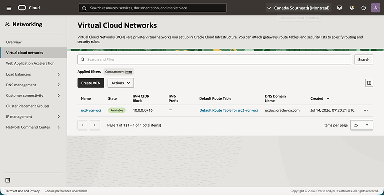
- Open the navigation menu, click on Networking and then on Virtual cloud networks.
- Notice the VCN
uc3-vcn-ociwith the IPv4 CIDR Block10.0.0.0/16.
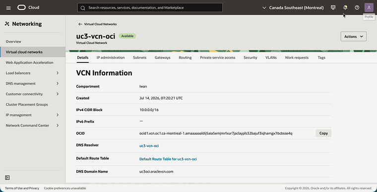
- Click on
uc3-vcn-oci. - Notice the IPv4 CIDR Block
10.0.0.0/16on the Details tab.
- Click on the Subnets tab.
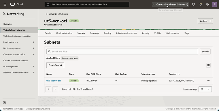
- Notice the subnet
uc3-subnet-ociwith the IPv4 CIDR Block10.0.1.0/24.
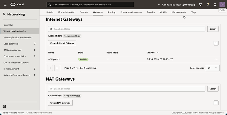
The internet gateway is only here so that you can reach the test instance over SSH.
- Click on the Gateways tab.
- Notice the internet gateway
uc3-igw-oci.
- Open the navigation menu, click on Compute and then on Instances.
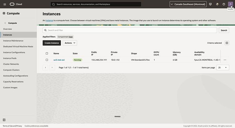
- Notice the instance
uc3-inst-ociwith the private IP address10.0.1.92.
Step 02: Review the simulated on-premises network
The on-premises network is simulated with a VCN in another region. It uses the same address space as the OCI side, which is the whole point of this tutorial. If you have a real on-premises network and router, you can read this step for reference and continue with Step 05.
- Select the Canada Southeast (Toronto) region.
- Open the navigation menu, click on Networking and then on Virtual cloud networks.
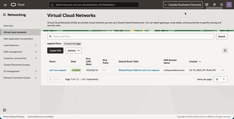
- Notice the VCN
uc3-vcn-onpremwith the same IPv4 CIDR Block10.0.0.0/16.
- Click on
uc3-vcn-onprem. - Notice the IPv4 CIDR Block
10.0.0.0/16on the Details tab.
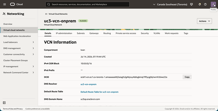
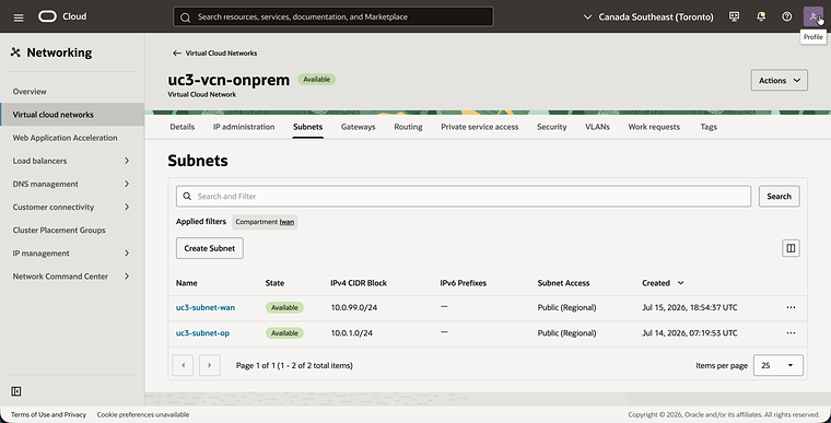
The VCN has two subnets. Together they give the Libreswan instance the two sides that a real router has.
- Click on the Subnets tab.
- Notice the two subnets:
uc3-subnet-wan(10.0.99.0/24), the outside of the on-premises router.uc3-subnet-op(10.0.1.0/24), the on-premises LAN. This is the range that overlaps with the OCI side.
- Click on the Gateways tab.
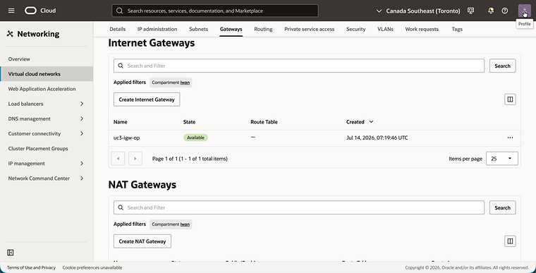
- Notice the internet gateway
uc3-igw-op. In this simulation it plays the role of the on-premises internet connection.
- Open the navigation menu, click on Compute and then on Instances.
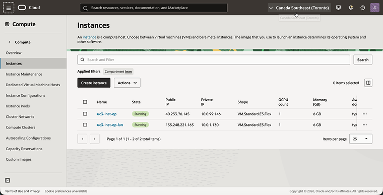
- Notice the two instances:
uc3-inst-op, the Libreswan router, with the public IP address40.233.76.145and the private IP address10.0.99.146in the WAN subnet. It has a second VNIC in the LAN subnet with the IP address10.0.1.164.uc3-inst-op-lan, a host on the LAN, with the private IP address10.0.1.130.
Step 03: Configure the security lists
The security lists must allow two kinds of traffic: the IPSec tunnel itself and the ping that we use as a test.
- IPSec: UDP port
500(IKE), UDP port4500(NAT traversal) and the ESP protocol. - ICMP: from the private ranges. Because of the translation, a ping from on-premises arrives in OCI with a source address in
192.168.20.0/24, and a ping from OCI arrives on-premises with a source address in192.168.10.0/24.
The lab allows ICMP from all three private ranges. That is broader than this tutorial needs. On the OCI side the only range that matters is the on-premises shadow CIDR 192.168.20.0/24. On the simulated on-premises side you need the OCI shadow CIDR 192.168.10.0/24 and also the local 10.0.1.0/24, because traffic from the LAN hosts passes through the LAN VNIC of the Libreswan router, and the security list is checked there as well.
- In
uc3-vcn-oci, click on the Security tab and click on the default security list. - Click on the Security rules tab.
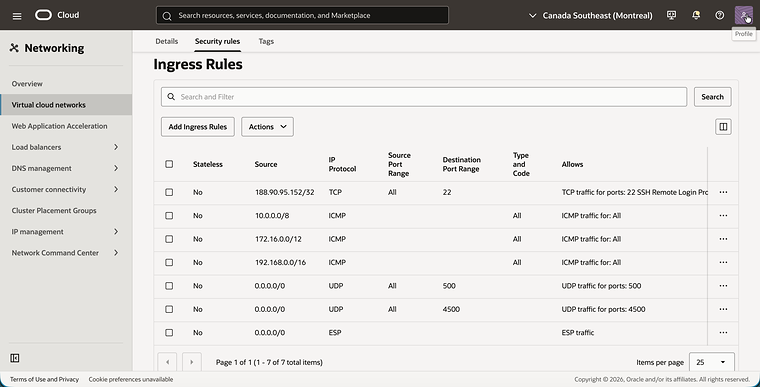
- Make sure the security list has the following ingress rules, and add the ones that are missing:
- TCP port
22from your own public IP address, for SSH. - ICMP from
10.0.0.0/8,172.16.0.0/12and192.168.0.0/16. - UDP port
500, UDP port4500and ESP from0.0.0.0/0.
- TCP port
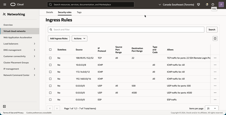
- Open the default security list of
uc3-vcn-onpremin the same way. - Make sure it has the same ingress rules.
Step 04: Configure the routing on the on-premises side
On-premises hosts must know how to reach OCI. They use the shadow CIDR of the OCI side, 192.168.10.0/24, and the route for it points to the on-premises router. This is the only thing the on-premises network has to know about the translation.
- In
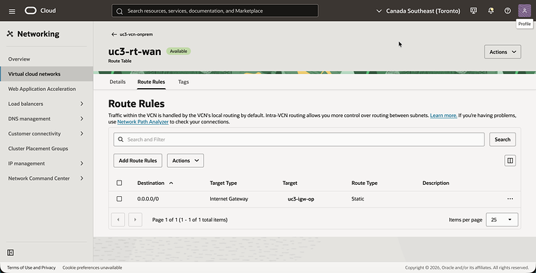
uc3-vcn-onprem, click on the Routing tab and click on the route tableuc3-rt-wan. This is the route table of the WAN subnet. - Notice the single route rule
0.0.0.0/0with the targetuc3-igw-op. The router uses it to reach the Oracle VPN endpoints over the internet.
- Go back and click on the route table
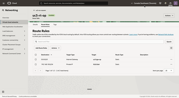
uc3-rt-op. This is the route table of the LAN subnet. - Add a route rule for the shadow CIDR of the OCI side, so that the route table has these two route rules:
0.0.0.0/0with the targetuc3-igw-op, for SSH access from the internet.192.168.10.0/24(the shadow CIDR of the OCI side) with the target type Private IP and the target10.0.1.164, the LAN address of the Libreswan router.
Step 05: Create the DRG and attach the VCN
Back on the OCI side we create the DRG. It gets a VCN attachment now, and two IPSec tunnel attachments are added automatically in the next step.
- Select the Canada Southeast (Montreal) region.
- Open the navigation menu, click on Networking, then on Customer connectivity and then on Dynamic routing gateway.
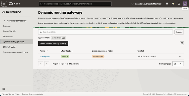
- Click on the Create dynamic routing gateway button and create a DRG with the name
uc3-drg-oci. - Notice that the DRG is Available.
- Click on
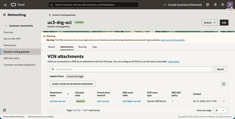
uc3-drg-ociand click on the Attachments tab. - Click on the Create virtual cloud network attachment button and create the attachment
uc3-att-vcn-ocifor the VCNuc3-vcn-oci. - Notice that the attachment uses the DRG route table
uc3-drgrt-vcn-ociand that it has no DRG NAT policy. The DRG route tables are configured in Step 09.
- Click on the attachment
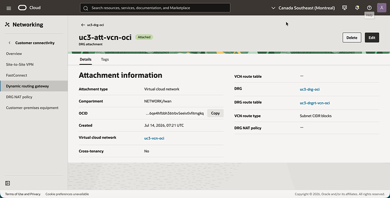
uc3-att-vcn-oci. - Notice the DRG route table
uc3-drgrt-vcn-ociand the empty DRG NAT policy field.
Step 06: Create the Site-to-Site VPN
The Site-to-Site VPN connects the DRG to the on-premises router. It needs a customer-premises equipment (CPE) object that represents the public IP address of the router, and an IPSec connection that creates two tunnels for redundancy.
- Open the navigation menu, click on Networking, then on Customer connectivity and then on Customer-premises equipment.
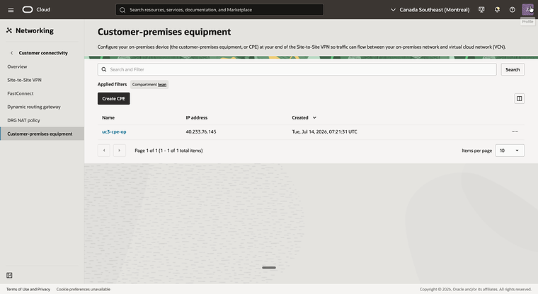
- Click on the Create CPE button and create a CPE with the name
uc3-cpe-opand the IP address40.233.76.145, the public IP address of the on-premises router. - Notice the CPE
uc3-cpe-opwith the IP address40.233.76.145.
- Click on Site-to-Site VPN in the menu on the left.
- Click on the Create IPSec connection button and create a connection with the following values:
- Name:
uc3-ipsec - Customer-premises equipment:
uc3-cpe-op - Dynamic routing gateway:
uc3-drg-oci - Routing type for both tunnels: Policy based routing
- IKE version for both tunnels: IKEv1
- Name:
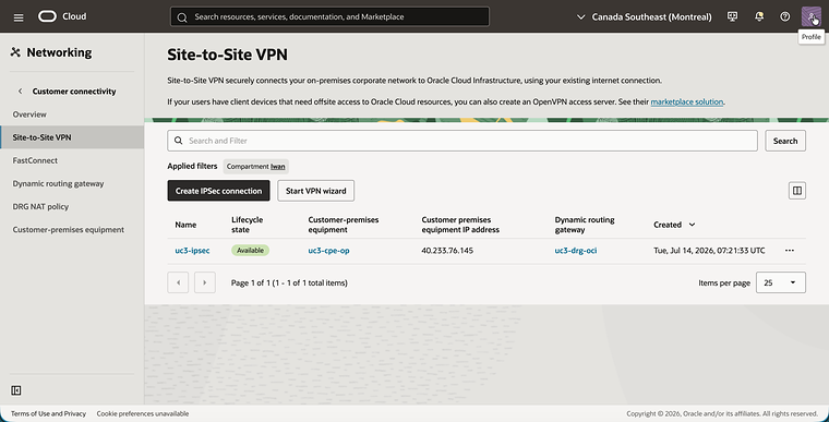
- Notice the IPSec connection
uc3-ipsecwith the CPEuc3-cpe-opand the DRGuc3-drg-oci.
- Click on
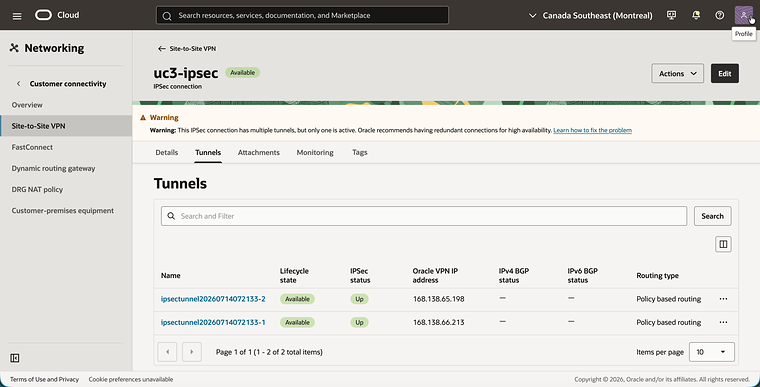
uc3-ipsecand click on the Tunnels tab. - Notice the two tunnels, each with its own Oracle VPN IP address (
168.138.66.213and168.138.65.198) and the Routing type Policy based routing. The IPSec status becomes Up after Step 08.
- Click on each tunnel and write down its Oracle VPN IP address and its Shared secret. You need both for the configuration of the on-premises router.
Step 07: Configure the encryption domain of the tunnels
This step is specific to NAT on DRG over a policy-based VPN, and it is where a configuration most often goes wrong. A policy-based tunnel has an encryption domain: a list of CIDRs on the Oracle side and a list of CIDRs on the on-premises side. The tunnel only carries traffic between those CIDRs.
The DRG applies the NAT rule before a packet goes into the tunnel and after it comes out. The packets inside the tunnel therefore look like this:
| Side of the tunnel | Address inside the tunnel | Why |
|---|---|---|
| Oracle | 192.168.10.0/24 |
The OCI side has already been translated to its shadow CIDR. |
| On-premises | 10.0.1.0/24 |
The on-premises side uses its real addresses. It is not aware of any NAT. |
So the Oracle side of the encryption domain is the shadow CIDR of OCI, not the real CIDR of the VCN.
There is a second reason to edit the encryption domain. In policy-based mode the DRG learns its routes towards the tunnel from the on-premises CIDRs of the encryption domain. The real on-premises CIDR 10.0.1.0/24 overlaps with the VCN and does not give the DRG a usable route. The instances in OCI send their traffic to the on-premises shadow CIDR 192.168.20.0/24, so that is the destination the DRG needs a route for. We get that route by adding 192.168.20.0/24 as a second on-premises CIDR.
- On the Tunnels tab of
uc3-ipsec, open the first tunnel and click on the Edit button. - Set the encryption domain as follows:
- Oracle Cloud CIDR blocks:
192.168.10.0/24 - On-premises CIDR blocks:
10.0.1.0/24and192.168.20.0/24
- Oracle Cloud CIDR blocks:
- Save the changes and repeat this for the second tunnel. You verify the result in Step 08, when the tunnels are up.
You can do the same with the OCI CLI. Repeat the command for both tunnels:
cat > tunnel-encryption-domain.json <<'EOF'{  "routing": "POLICY",  "encryptionDomainConfig": {    "oracleTrafficSelector": ["192.168.10.0/24"],    "cpeTrafficSelector": ["10.0.1.0/24", "192.168.20.0/24"]  }}EOF
oci raw-request --http-method PUT \ --target-uri "https://iaas.ca-montreal-1.oraclecloud.com/20160918/ipsecConnections/<ipsec_connection_ocid>/tunnels/<tunnel_ocid>" \ --request-body file://tunnel-encryption-domain.jsonStep 08: Configure Libreswan on the on-premises side
Now the on-premises router is configured to bring up both tunnels. If you use a real router, configure it with the values from this step: IKEv1, a pre-shared key, and the traffic selectors 10.0.1.0/24 (local) and 192.168.10.0/24 (remote).
With Libreswan there is one thing to take care of. Both tunnels use exactly the same traffic selectors, and the Linux kernel can hold only one IPSec policy for a given pair of subnets. Two plain connections with identical selectors keep taking that policy from each other, and the tunnels flap. The solution is to give each connection its own mark and its own VTI interface, so that the kernel can tell them apart.
- Connect to
uc3-inst-opwith SSH. - Create the file
/etc/ipsec.d/uc3-t2.conffor the first tunnel (168.138.66.213):
conn uc3-t2 auto=start authby=secret keyexchange=ike ikev2=no type=tunnel left=%defaultroute leftid=40.233.76.145 leftsubnet=10.0.1.0/24 right=168.138.66.213 rightid=168.138.66.213 rightsubnet=192.168.10.0/24 ike=aes256-sha256;modp1536 phase2alg=aes256-sha256 pfs=yes encapsulation=yes ikelifetime=28800s salifetime=3600s mark=1/0xffffffff vti-interface=vti1 vti-routing=no vti-shared=no- Create the file
/etc/ipsec.d/uc3.conffor the second tunnel (168.138.65.198). It is the same, except for the name, the Oracle VPN IP address, the mark and the VTI interface:
conn uc3 auto=start authby=secret keyexchange=ike ikev2=no type=tunnel left=%defaultroute leftid=40.233.76.145 leftsubnet=10.0.1.0/24 right=168.138.65.198 rightid=168.138.65.198 rightsubnet=192.168.10.0/24 ike=aes256-sha256;modp1536 phase2alg=aes256-sha256 pfs=yes encapsulation=yes ikelifetime=28800s salifetime=3600s mark=2/0xffffffff vti-interface=vti2 vti-routing=no vti-shared=no- Create a secrets file for each tunnel with the shared secret from Step 06, and restrict its permissions with
chmod 600:
40.233.76.145 168.138.66.213 : PSK "<shared secret of tunnel 1>"
# /etc/ipsec.d/uc3.secrets40.233.76.145 168.138.65.198 : PSK "<shared secret of tunnel 2>"- Start Libreswan:
sudo systemctl enable --now ipsecsudo systemctl restart ipsecNotice that leftsubnet is the real on-premises CIDR and rightsubnet is the shadow CIDR of OCI. This matches the encryption domain from Step 07.
The last piece is the route to the OCI shadow CIDR. With vti-routing=no Libreswan does not add routes itself, so we add one route per tunnel with a different metric. The first tunnel is preferred and the second one takes over when the first one fails.
sudo ip route replace 192.168.10.0/24 dev vti1 metric 100sudo ip route replace 192.168.10.0/24 dev vti2 metric 200- Run
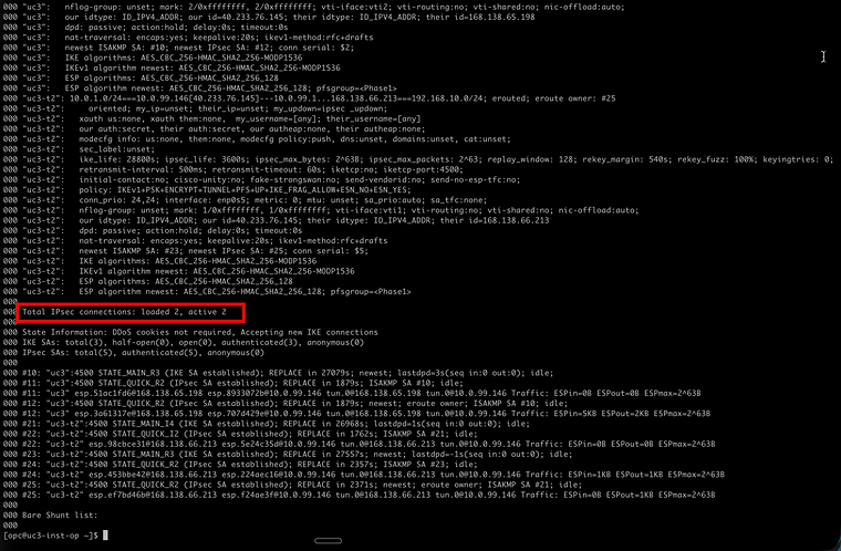
sudo ipsec statusto verify the result. - Notice the line Total IPsec connections: loaded 2, active 2, and notice that each connection has its own mark and VTI interface (
mark: 1/0xffffffffwithvti-iface:vti1, andmark: 2/0xffffffffwithvti-iface:vti2).
- Go back to the OCI Console and open the Tunnels tab of
uc3-ipsec. - Notice that the IPSec status of both tunnels is Up.
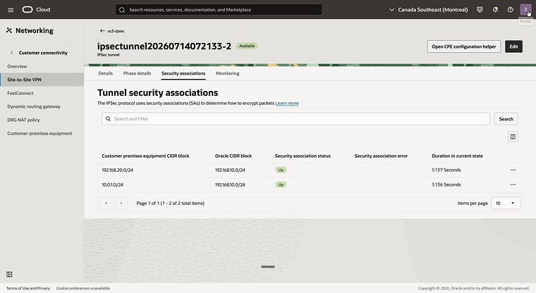
- Click on the first tunnel and click on the Security associations tab.
- Notice the two entries, one for each on-premises CIDR of the encryption domain from Step 07, both with the Oracle CIDR block
192.168.10.0/24and the status Up.
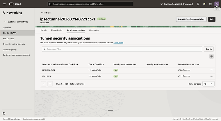
- Go back, click on the second tunnel and click on the Security associations tab.
- Notice the same two entries with the status Up.
Step 09: Configure the DRG route tables
The DRG has two kinds of attachments now, and each kind gets its own DRG route table.
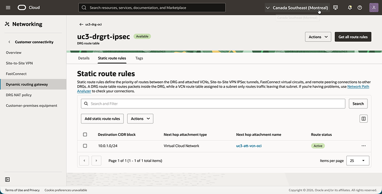
The route table of the IPSec tunnel attachments handles traffic that arrives from on-premises. The NAT policy on the tunnel attachment translates the packet first, and the DRG looks up the translated destination. That destination is the real CIDR of the VCN, so the table has a static route for 10.0.1.0/24 to the VCN attachment.
- In
uc3-drg-oci, click on the Routing tab and create a DRG route table with the nameuc3-drgrt-ipsec. - Click on the Static route rules tab and click on the Add static route rules button.
- Add a rule with the Destination CIDR block
10.0.1.0/24and the Next hop attachmentuc3-att-vcn-oci. - Notice that the static route is Active.
- Go back to the Attachments tab of
uc3-drg-oci, scroll down to IPSec tunnel attachments and edit both tunnel attachments to selectuc3-drgrt-ipsecas their DRG route table.
The route table of the VCN attachment handles traffic that comes from the VCN and is addressed to the on-premises shadow CIDR 192.168.20.0/24. This traffic has to go to the tunnel. You cannot create that route as a static route: a static route rule in a DRG route table accepts a VCN attachment or a remote peering connection as next hop, but not an IPSec tunnel. The route has to be learned dynamically, with an import route distribution.
-
On the Routing tab of
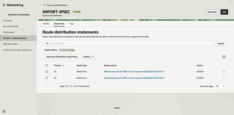
uc3-drg-oci, create an import route distribution with the nameIMPORT-IPSECand add two statements:- Priority
10, Match type Attachment, the attachment of the first IPSec tunnel, Action Accept. - Priority
20, Match type Attachment, the attachment of the second IPSec tunnel, Action Accept.
- Priority
-
Create a DRG route table with the name
uc3-drgrt-vcn-ociand selectIMPORT-IPSECas its Import route distribution. -
Edit the attachment
uc3-att-vcn-ociand selectuc3-drgrt-vcn-ocias its DRG route table. -
Click on the import route distribution
IMPORT-IPSECand click on the Statements tab. -
Notice the two statements, one for each IPSec tunnel attachment, both with the action ACCEPT.
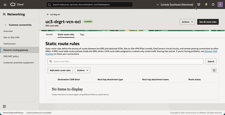
- Click on the DRG route table
uc3-drgrt-vcn-ociand click on the Static route rules tab. - Notice that the table has no static route rules. This is expected.
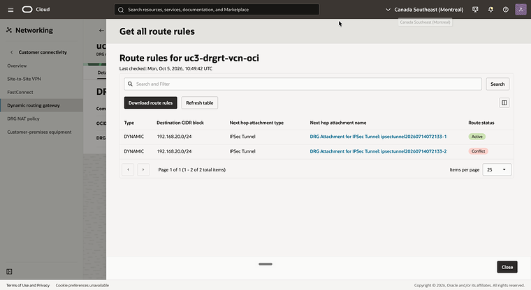
- Go back to the Details tab and click on the Get all route rules button.
- Notice the two routes of the type DYNAMIC for
192.168.20.0/24, each with an IPSec tunnel attachment as next hop. This is the on-premises CIDR that you added to the encryption domain in Step 07. - Notice the Route status. The DRG uses the route with the status Active. The route through the other tunnel has the status Conflict, which here only means that it is the standby for the same destination.
Step 10: Configure the VCN route table on the OCI side
The instances in the VCN must send traffic for the on-premises shadow CIDR to the DRG.
- In
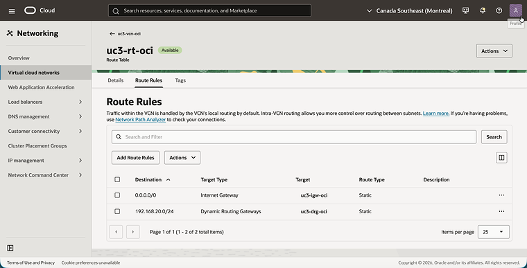
uc3-vcn-oci, click on the Routing tab and click on the route tableuc3-rt-oci. This is the route table that is assigned touc3-subnet-oci. - Click on the Route Rules tab.
- Add a route rule for the on-premises shadow CIDR, so that the route table has these two route rules:
0.0.0.0/0with the targetuc3-igw-oci, for SSH access from the internet.192.168.20.0/24(the shadow CIDR of on-premises) with the targetuc3-drg-oci.
Step 11: Create the DRG NAT policy and rule
This is the step the whole tutorial is about. One DRG NAT policy with one rule does all the translation, in both directions.
The policy is associated with the IPSec tunnel attachments, so the rule is written for traffic that arrives from on-premises. Such a packet has an on-premises host as source (10.0.1.x) and the shadow address of an OCI instance as destination (192.168.10.x):
| Original | Translated | Meaning | |
|---|---|---|---|
| Source | 10.0.1.0/24 |
192.168.20.0/24 |
The real addresses of on-premises are presented in OCI as 192.168.20.0/24. |
| Destination | 192.168.10.0/24 |
10.0.1.0/24 |
The shadow CIDR of OCI is replaced with the real CIDR of the VCN. |
- Open the navigation menu, click on Networking, then on Customer connectivity and then on DRG NAT policy.
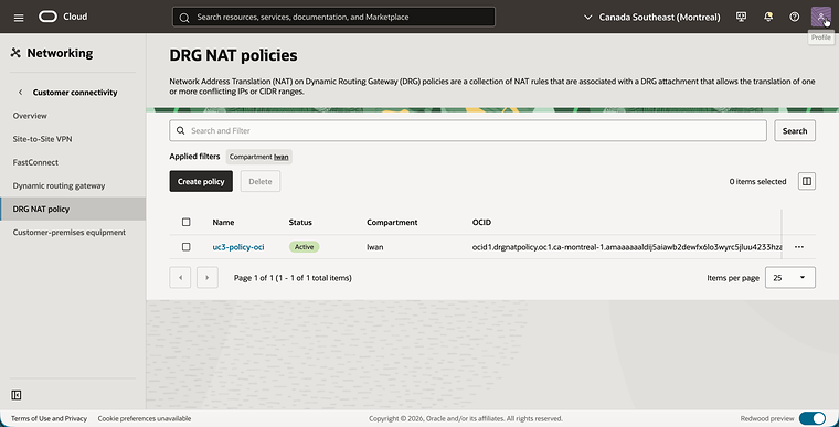
- Click on the Create policy button and create a policy with the name
uc3-policy-oci. - Notice that the policy is Active.
- Click on
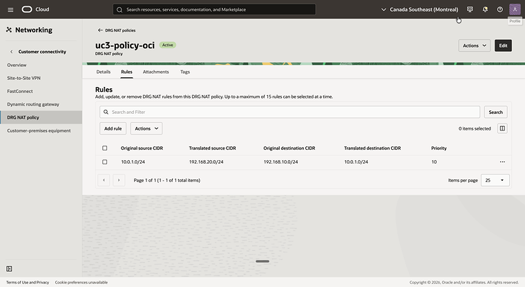
uc3-policy-ociand click on the Rules tab. - Click on the Add rule button and add a rule with the following values:
- Priority:
10 - Original source CIDR:
10.0.1.0/24 - Translated source CIDR:
192.168.20.0/24 - Original destination CIDR:
192.168.10.0/24 - Translated destination CIDR:
10.0.1.0/24
- Priority:
- Notice that the rule is listed on the Rules tab.
Step 12: Associate the NAT policy with the IPSec tunnel attachments
The policy is associated with both IPSec tunnel attachments, so that the translation is the same no matter which tunnel carries the traffic.
- In
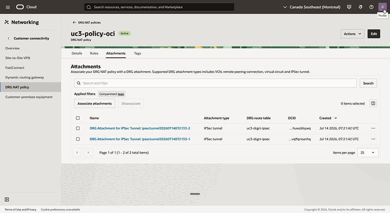
uc3-policy-oci, click on the Attachments tab. - Click on the Associate attachments button, select the two DRG Attachment for IPSec Tunnel attachments and confirm.
- Notice that both attachments are listed with the Attachment type IPSec tunnel, together with their DRG route table
uc3-drgrt-ipsec.
Step 13: Test the connectivity
Everything is in place, so it is time to send a packet. The last octet of an address is preserved by the 1:1 translation, which tells you which address to ping:
| Instance | Real IP address | Address to use from the other side |
|---|---|---|
uc3-inst-oci |
10.0.1.92 |
192.168.10.92 |
uc3-inst-op-lan |
10.0.1.130 |
192.168.20.130 |
This is what happens to a ping from uc3-inst-oci to the on-premises host:
| Where | Source | Destination | What happens |
|---|---|---|---|
Leaves uc3-inst-oci |
10.0.1.92 |
192.168.20.130 |
The route table uc3-rt-oci sends 192.168.20.0/24 to the DRG. |
Route lookup in uc3-drgrt-vcn-oci |
10.0.1.92 |
192.168.20.130 |
The dynamic route for 192.168.20.0/24 points to an IPSec tunnel. |
| Leaves the DRG on the tunnel attachment | 192.168.10.92 |
10.0.1.130 |
The DRG applies the reverse of the rule in uc3-policy-oci. The packet now matches the encryption domain. |
Arrives at uc3-inst-op-lan |
192.168.10.92 |
10.0.1.130 |
The host sees a ping from the shadow address of the OCI instance. |
And this is the reply:
| Where | Source | Destination | What happens |
|---|---|---|---|
Leaves uc3-inst-op-lan |
10.0.1.130 |
192.168.10.92 |
The route table uc3-rt-op sends 192.168.10.0/24 to the router 10.0.1.164. |
| On-premises router | 10.0.1.130 |
192.168.10.92 |
The packet matches the tunnel selectors and is encrypted. |
| Enters the DRG on the tunnel attachment | 192.168.20.130 |
10.0.1.92 |
The rule in uc3-policy-oci translates source and destination. |
Route lookup in uc3-drgrt-ipsec |
192.168.20.130 |
10.0.1.92 |
10.0.1.0/24 points to uc3-att-vcn-oci. |
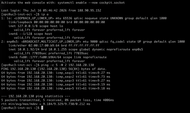
- Connect to
uc3-inst-ociwith SSH. - Run
ip aand notice that the instance has the IP address10.0.1.92. - Run
ping -c 5 -W 2 192.168.20.130to ping the shadow address of the on-premises host. - Notice that all five packets are answered.
- Connect to
uc3-inst-op-lanwith SSH. - Run
ip aand notice that the host has the IP address10.0.1.130, in the same subnet range as the OCI instance. - Run
ping -c 5 -W 2 192.168.10.92to ping the shadow address ofuc3-inst-oci. - Notice that all five packets are answered.
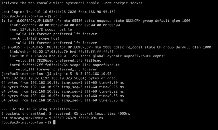
A packet capture on the on-premises host shows the translation at work. The host never sees the real address 10.0.1.92 of the OCI instance, only its shadow address:
[opc@uc3-inst-op-lan ~]$ sudo tcpdump -ni any icmpIP 192.168.10.92 > 10.0.1.130: ICMP echo request, id 11, seq 1, length 64IP 10.0.1.130 > 192.168.10.92: ICMP echo reply, id 11, seq 1, length 64Conclusion
An OCI VCN and an on-premises network with exactly the same subnet CIDR now communicate over a Site-to-Site VPN. Nothing was re-addressed, and the on-premises router does no NAT at all. It only needs a tunnel with the right selectors and a route to the OCI shadow CIDR. The translation is done by the DRG on the IPSec tunnel attachments, with a single rule.
Compared to the earlier parts, the VPN adds two requirements that are easy to miss. The encryption domain must describe the packets as they are inside the tunnel, which means the shadow CIDR on the Oracle side and the real CIDR on the on-premises side. And because a static DRG route cannot point to an IPSec tunnel, the route to the on-premises shadow CIDR has to be learned from the tunnel, by adding that shadow CIDR to the on-premises side of the encryption domain and importing it into the DRG route table of the VCN attachment.
The rule itself follows the same principle as in the rest of the series: it is written for traffic that enters the DRG through the attachment that holds the policy. In NAT on DRG Part 4: Shared services VCN the same technique is used with source NAT only, to give several overlapping VCNs access to one shared services VCN.
Related articles