Originally published as an Oracle tutorial on Oracle Docs. Part 2 of 5 in the NAT on DRG series.
Introduction
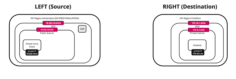
In NAT on DRG Part 1: Overlapping CIDRs between two local VCNs two VCNs with the same CIDR were attached to one Dynamic Routing Gateway (DRG) in one region. In practice overlapping networks are often further apart: a production environment in one Oracle Cloud Infrastructure (OCI) region and a copy of it in another region, or two business units that each built their own landing zone in their own region with the same address plan.
Regions are connected with a remote peering connection (RPC) between two DRGs. An RPC normally refuses to be useful when both sides advertise the same CIDR, because neither DRG can tell local from remote. NAT on DRG solves this by translating the addresses on the RPC attachment, so that each region is known to the other one under a unique “shadow” CIDR.
| Region | VCN | Real subnet CIDR | Shadow CIDR seen by the other region |
|---|---|---|---|
| Canada Southeast (Montreal), YUL | uc2-vcn-yul |
10.0.1.0/24 |
192.168.10.0/24 |
| Canada Southeast (Toronto), YYZ | uc2-vcn-yyz |
10.0.1.0/24 |
192.168.20.0/24 |
The difference with Part 1 is the place where the NAT policy sits. In Part 1 the policies were associated with the VCN attachments. In this tutorial they are associated with the RPC attachments, and the VCN attachments have no policy at all. This has a useful side effect: the translation applies to everything that crosses the RPC, no matter which VCN in the region it comes from, and VCNs that do not overlap are not affected.
This tutorial shows two ways to configure the rules, and both are tested:
- Option 1: a single rule in one region. One rule on the Montreal side translates both source and destination. The Toronto side has no rules.
- Option 2: a rule in each region. Each region has one destination NAT rule for its own shadow CIDR.
Other Use Cases
This tutorial is part of a series of five. Every part solves a different overlap scenario with the same building blocks.
- Part 1: NAT on DRG Part 1: Overlapping CIDRs between two local VCNs
- Part 2 (this article): NAT on DRG Part 2: Overlapping CIDRs between multiple remote VCNs
- Part 3: NAT on DRG Part 3: Overlapping CIDRs between OCI and On-Premises
- Part 4: NAT on DRG Part 4: Shared services VCN
- Part 5: NAT on DRG Part 5: Overlapping CIDRs between OCI and On-Premises with BGP
Diagram
Overlapping subnet CIDRs in different OCI regions resolved with stateless 1:1 NAT on DRG (This scenario maintains the translation for all VCNs in the region, including non-overlapping ones)
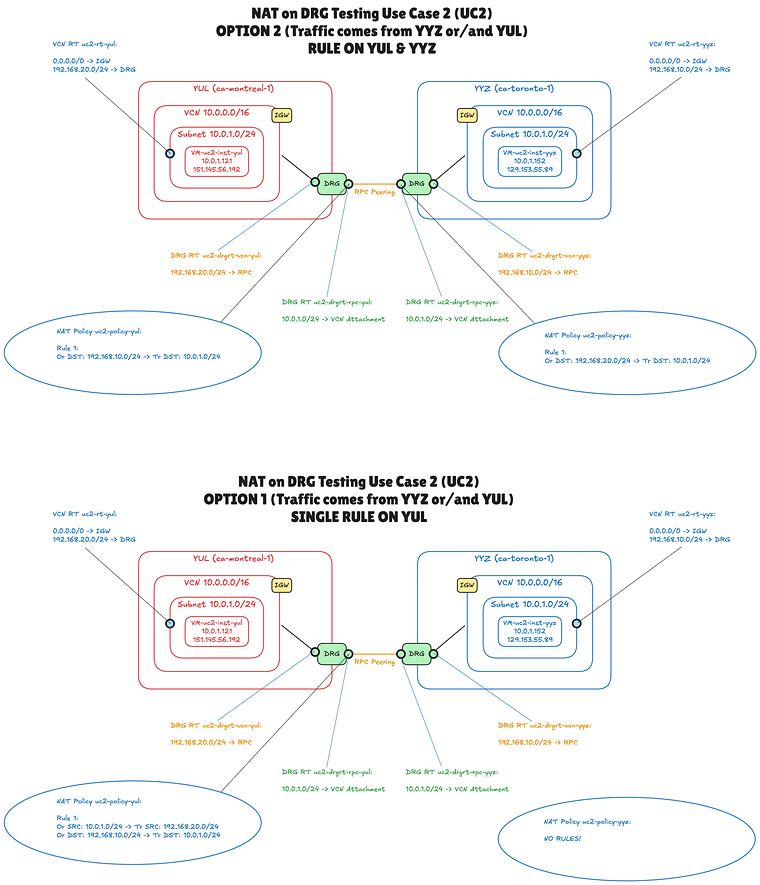
The diagram shows the same topology twice, once for each rule option. Everything except the NAT rules is identical:
- Two VCNs, one in Montreal and one in Toronto, both
10.0.0.0/16with a subnet10.0.1.0/24, each with one test instance. - Two DRGs, one per region, connected with a remote peering connection.
- Two VCN route tables (blue text). Each one sends the shadow CIDR of the other region to the local DRG.
- Four DRG route tables (orange text), two per DRG. The table on the VCN attachment sends the shadow CIDR of the other region to the RPC. The table on the RPC attachment sends
10.0.1.0/24to the local VCN. - Two DRG NAT policies (the ellipses), one per region, each associated with the RPC attachment of its DRG.
Prerequisites
- An OCI tenancy that is subscribed to two regions, and a compartment in which you are allowed to manage networking resources (VCNs, DRGs, remote peering connections, DRG route tables and DRG NAT policies) and compute instances.
- Two VCNs with overlapping CIDRs that already exist, one in each region. This tutorial does not create them. In the lab they are
uc2-vcn-yulanduc2-vcn-yyz, both10.0.0.0/16, each with one public subnet10.0.1.0/24, an internet gateway, and a route table (uc2-rt-yulanduc2-rt-yyz) that is assigned to the subnet and sends0.0.0.0/0to the internet gateway. Steps 01 and 04 walk through this starting point. - DRGs that support NAT. NAT on DRG is not available on legacy (V1) DRGs, and not on DRGs that have disintermediation, high-throughput mode or route unification enabled. Newly created DRGs work.
- Two compute instances to test with, one in each region. In this tutorial they are called
uc2-inst-yul(10.0.1.121) anduc2-inst-yyz(10.0.1.152). Each has a public IP address so you can reach it with SSH. - An SSH key pair for the instances, and the public IP address you connect from (to allow it in the security lists).
- Basic knowledge of remote peering, VCN route tables and DRG route tables.
Steps
- STEP 01: Review the network in Montreal (YUL)
- STEP 02: Create the DRG, the RPC and the DRG route tables in Montreal
- STEP 03: Create the DRG NAT policy in Montreal
- STEP 04: Review the network in Toronto (YYZ)
- STEP 05: Create the DRG, the RPC and the DRG route tables in Toronto
- STEP 06: Create the DRG NAT policy in Toronto
- STEP 07: Configure the NAT rules, option 1: a single rule in one region
- STEP 08: Configure the NAT rules, option 2: a rule in each region
Step 01: Review the network in Montreal (YUL)
We start in the first region. The VCN here is an ordinary VCN with one public subnet. The only thing that matters for this tutorial is its address space, which is identical to the VCN in the other region.
- Select the Canada Southeast (Montreal) region.
- Open the navigation menu, click on Networking and then on Virtual cloud networks.
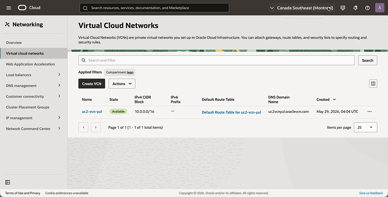
- Notice the VCN
uc2-vcn-yulwith the IPv4 CIDR Block10.0.0.0/16.
- Click on
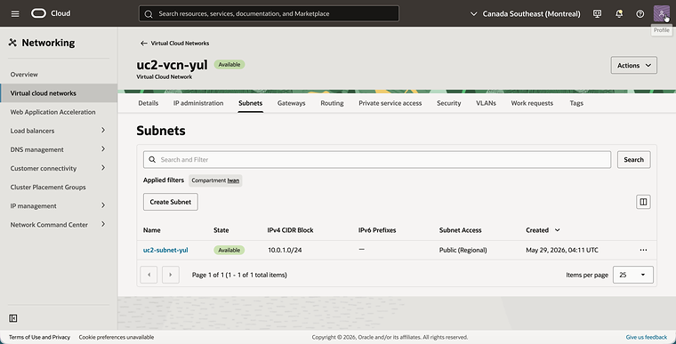
uc2-vcn-yuland click on the Subnets tab. - Notice the subnet
uc2-subnet-yulwith the IPv4 CIDR Block10.0.1.0/24.
The internet gateway is only here so that you can reach the test instance over SSH.
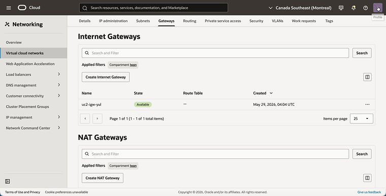
- Click on the Gateways tab.
- Notice the internet gateway
uc2-igw-yul.
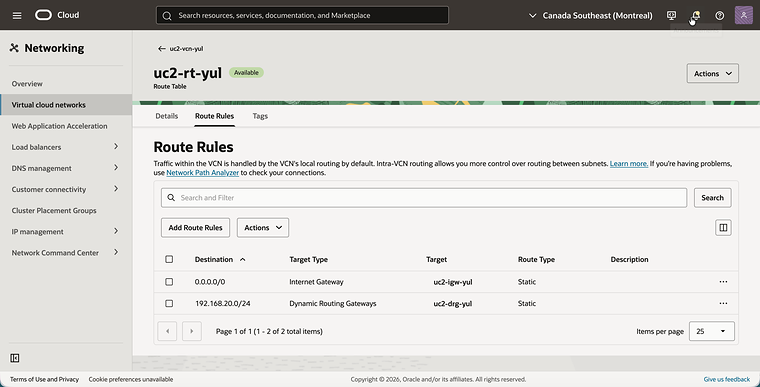
The instances in Montreal reach Toronto on its shadow CIDR 192.168.20.0/24, so that is the destination that goes to the DRG.
- Click on the Routing tab and click on the route table
uc2-rt-yul. This is the route table that is assigned touc2-subnet-yul. - Click on the Route Rules tab.
- Make sure the route table has these two route rules. Add the second one after Step 02, because its target is the DRG that you create there:
0.0.0.0/0with the targetuc2-igw-yul, for SSH access from the internet.192.168.20.0/24(the shadow CIDR of Toronto) with the targetuc2-drg-yul.
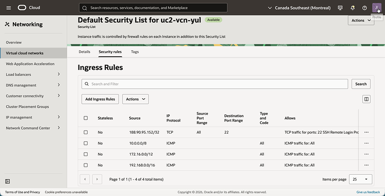
The test is a ping, so the security list must allow ICMP. A ping from Toronto arrives with a source address in a shadow range, not in 10.0.1.0/24.
The lab allows ICMP from all three private ranges. That is broader than this tutorial needs. The minimum is one ICMP rule per VCN, with the shadow CIDR of the other region as source: 192.168.20.0/24 in Montreal and 192.168.10.0/24 in Toronto.
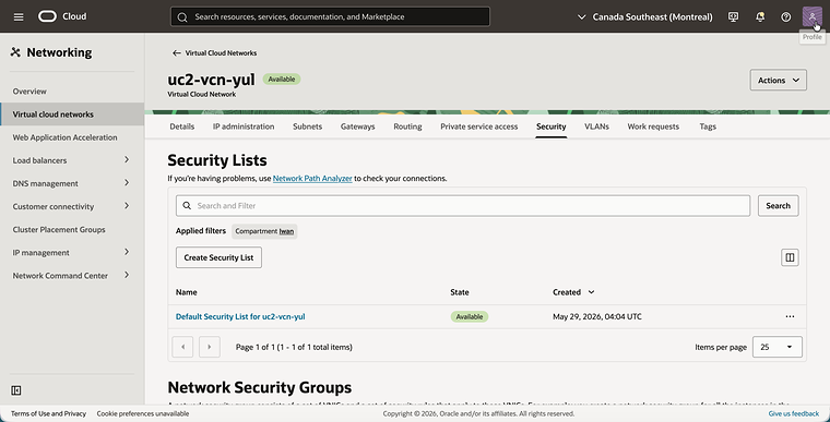
- Go back to the VCN and click on the Security tab.
- Click on Default Security List for uc2-vcn-yul.
- Click on the Security rules tab.
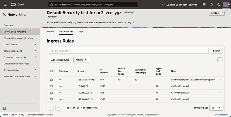
- Make sure the security list has the following ingress rules, and add the ones that are missing:
- TCP port
22from your own public IP address, for SSH. - ICMP from
10.0.0.0/8,172.16.0.0/12and192.168.0.0/16.
- TCP port
Step 02: Create the DRG, the RPC and the DRG route tables in Montreal
Each region has its own DRG. The DRG in Montreal gets two attachments: one for the VCN and one for the remote peering connection to Toronto. Each attachment gets its own DRG route table. The autogenerated tables do not help here: the shadow CIDR of Toronto is not advertised by any attachment, so the route to it has to be a static route. Two small tables with one static route each keep the routing explicit.
The screenshots in this step show the end result. The DRG route tables uc2-drgrt-vcn-yul and uc2-drgrt-rpc-yul are not created automatically. Create them on the Routing tab of the DRG, add the static route that is shown for each of them, and select them as the DRG route table of the VCN attachment and of the RPC attachment. The static route to the RPC can only be added after the RPC exists.
- Open the navigation menu, click on Networking, then on Customer connectivity and then on Dynamic routing gateway.
- Click on the Create dynamic routing gateway button and create a DRG with the name
uc2-drg-yul. - Notice that the DRG is Available.
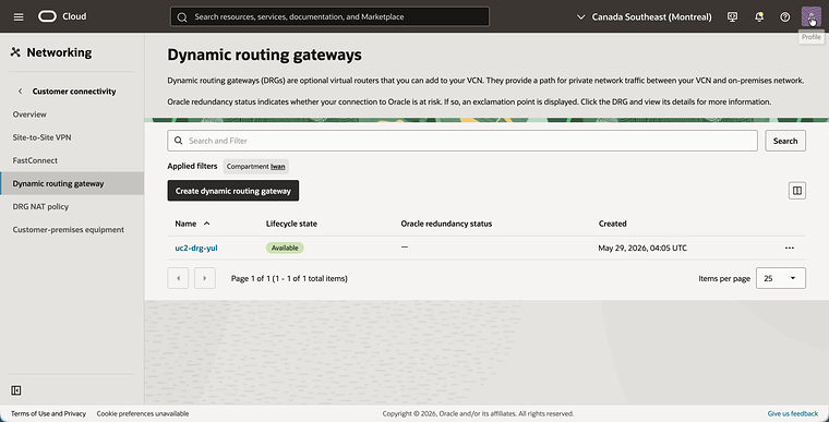
- Click on
uc2-drg-yuland click on the Attachments tab. - Click on the Create virtual cloud network attachment button and create the attachment
uc2-att-vcn-yulfor the VCNuc2-vcn-yul. - Notice that the attachment uses the DRG route table
uc2-drgrt-vcn-yuland that it has no DRG NAT policy.
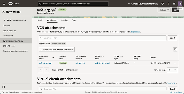
The DRG route table of the VCN attachment handles traffic that comes from the VCN. It sends the shadow CIDR of Toronto to the RPC.
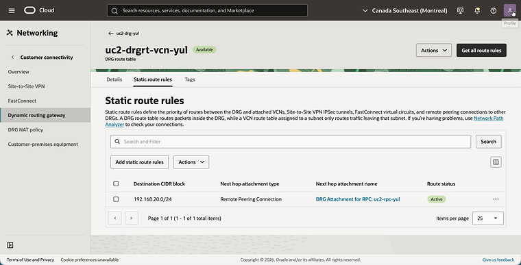
- Click on the DRG route table
uc2-drgrt-vcn-yuland click on the Static route rules tab. - Notice the static route with the Destination CIDR block
192.168.20.0/24and the next hop DRG Attachment for RPC: uc2-rpc-yul.
- Go back to the Attachments tab of
uc2-drg-yuland scroll down to Remote peering connection attachments. - Click on the Create remote peering connection button and create an RPC with the name
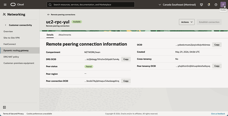
uc2-rpc-yul. - Notice that the RPC attachment is created automatically. After the next steps it shows the DRG route table
uc2-drgrt-rpc-yul, the peering status Peered and the DRG NAT policyuc2-policy-yul.
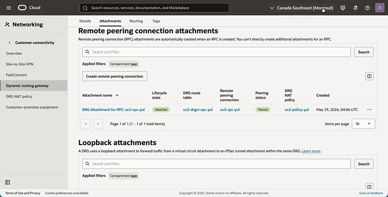
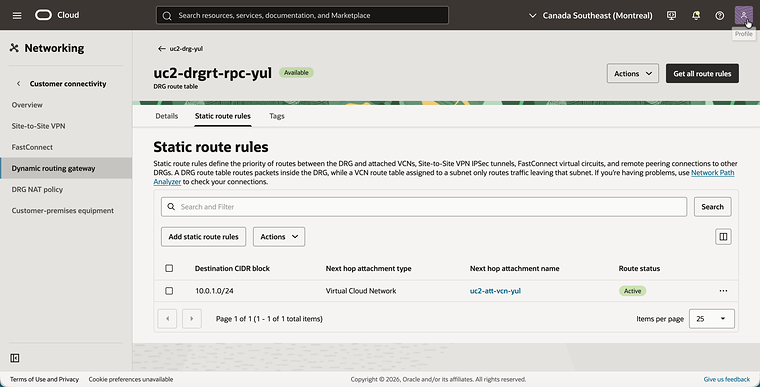
The DRG route table of the RPC attachment handles traffic that arrives from Toronto. The destination in this table is the real CIDR 10.0.1.0/24, because the NAT policy on the RPC attachment has already translated the destination by the time the DRG does its route lookup.
- Click on the DRG route table
uc2-drgrt-rpc-yuland click on the Static route rules tab. - Notice the static route with the Destination CIDR block
10.0.1.0/24and the next hopuc2-att-vcn-yul.
- Go back and click on the remote peering connection
uc2-rpc-yul. - Notice the Peer status. It becomes Peered when the connection with the RPC in Toronto is established in Step 05.
Step 03: Create the DRG NAT policy in Montreal
The NAT policy is created first and filled with rules later. A policy without rules translates nothing, so it is safe to associate it with the RPC attachment already.
- Open the navigation menu, click on Networking, then on Customer connectivity and then on DRG NAT policy.
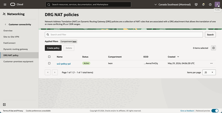
- Click on the Create policy button and create a policy with the name
uc2-policy-yul. - Notice that the policy is Active.
- Click on
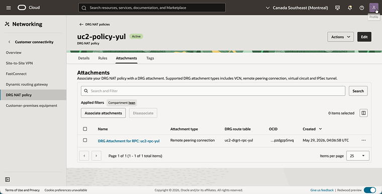
uc2-policy-yuland click on the Attachments tab. - Click on the Associate attachments button, select DRG Attachment for RPC: uc2-rpc-yul and confirm.
- Notice that the RPC attachment is listed with the Attachment type Remote peering connection, together with its DRG route table
uc2-drgrt-rpc-yul.
Step 04: Review the network in Toronto (YYZ)
Toronto is the mirror image of Montreal. The VCN has the same CIDR, and the route table points to the shadow CIDR of Montreal.
- Select the Canada Southeast (Toronto) region.
- Open the navigation menu, click on Networking and then on Virtual cloud networks.
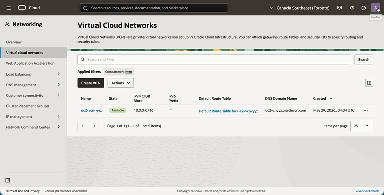
- Notice the VCN
uc2-vcn-yyzwith the same IPv4 CIDR Block10.0.0.0/16.
- Click on
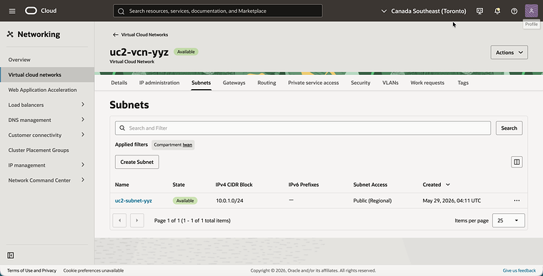
uc2-vcn-yyzand click on the Subnets tab. - Notice the subnet
uc2-subnet-yyzwith the same IPv4 CIDR Block10.0.1.0/24.
- Click on the Gateways tab.
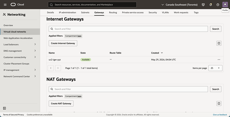
- Notice the internet gateway
uc2-igw-yyz.
- Click on the Routing tab and click on the route table
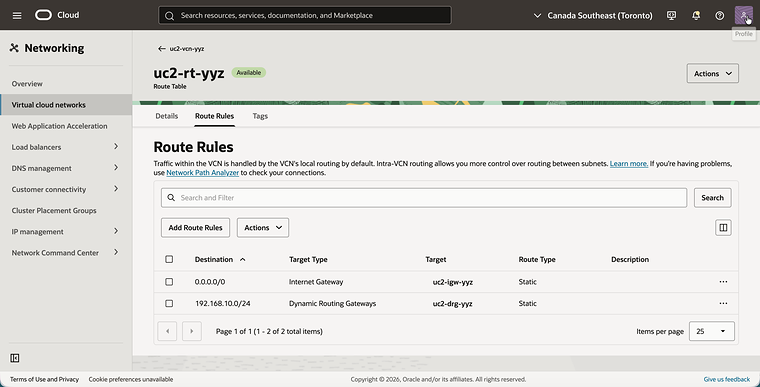
uc2-rt-yyz. - Click on the Route Rules tab.
- Make sure the route table has these two route rules. Add the second one after Step 05, because its target is the DRG that you create there:
0.0.0.0/0with the targetuc2-igw-yyz.192.168.10.0/24(the shadow CIDR of Montreal) with the targetuc2-drg-yyz.
- Go back to the VCN and click on the Security tab.
- Click on Default Security List for uc2-vcn-yyz.
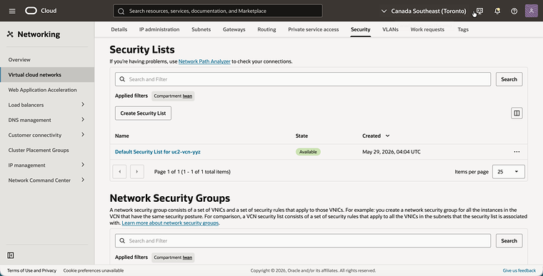
- Click on the Security rules tab.
- Make sure the ingress rules are the same as in Montreal.
Step 05: Create the DRG, the RPC and the DRG route tables in Toronto
The DRG in Toronto is built in the same way, and at the end of this step the two RPCs are connected to each other.
As in Montreal, the DRG route tables uc2-drgrt-vcn-yyz and uc2-drgrt-rpc-yyz are not created automatically. Create them, add the static route that is shown for each of them, and select them on the two attachments.
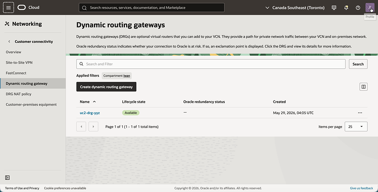
- Open the navigation menu, click on Networking, then on Customer connectivity and then on Dynamic routing gateway.
- Click on the Create dynamic routing gateway button and create a DRG with the name
uc2-drg-yyz. - Notice that the DRG is Available.
- Click on
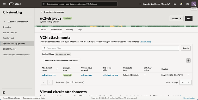
uc2-drg-yyzand click on the Attachments tab. - Click on the Create virtual cloud network attachment button and create the attachment
uc2-att-vcn-yyzfor the VCNuc2-vcn-yyz. - Notice that the attachment uses the DRG route table
uc2-drgrt-vcn-yyzand that it has no DRG NAT policy.
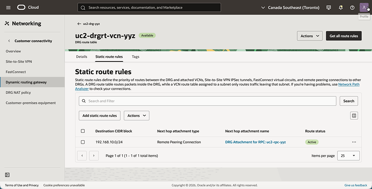
- Click on the DRG route table
uc2-drgrt-vcn-yyzand click on the Static route rules tab. - Notice the static route with the Destination CIDR block
192.168.10.0/24and the next hop DRG Attachment for RPC: uc2-rpc-yyz.
- Go back to the Attachments tab of
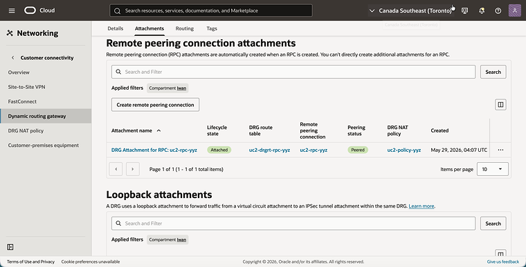
uc2-drg-yyzand scroll down to Remote peering connection attachments. - Click on the Create remote peering connection button and create an RPC with the name
uc2-rpc-yyz. - Notice the RPC attachment with the DRG route table
uc2-drgrt-rpc-yyz, the peering status Peered and the DRG NAT policyuc2-policy-yyz.
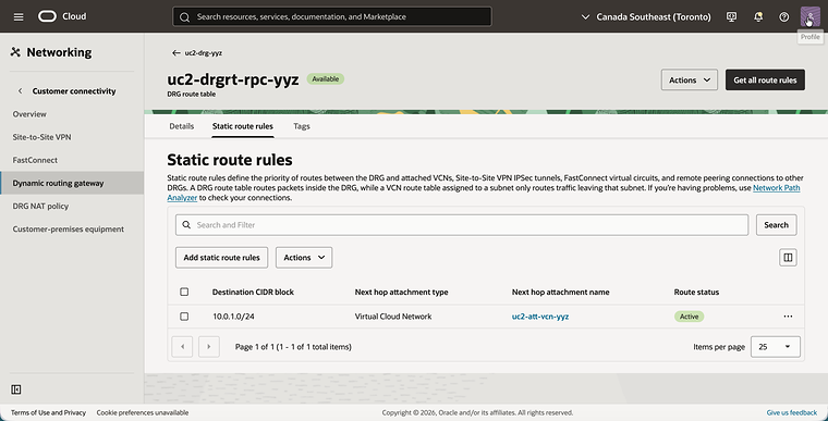
- Click on the DRG route table
uc2-drgrt-rpc-yyzand click on the Static route rules tab. - Notice the static route with the Destination CIDR block
10.0.1.0/24and the next hopuc2-att-vcn-yyz.
Now the two regions can be connected. You do this from one side only.
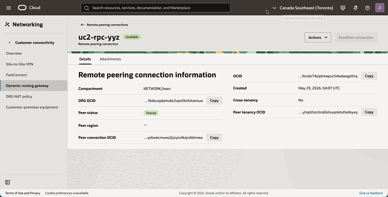
- Go back and click on the remote peering connection
uc2-rpc-yyz. - Click on the Establish connection button, select the Canada Southeast (Montreal) region and enter the OCID of
uc2-rpc-yul. - Notice that the Peer status changes to Peered.
Step 06: Create the DRG NAT policy in Toronto
Toronto gets its own policy, also associated with the RPC attachment.
- Open the navigation menu, click on Networking, then on Customer connectivity and then on DRG NAT policy.
- Click on the Create policy button and create a policy with the name
uc2-policy-yyz. - Notice that the policy is Active.
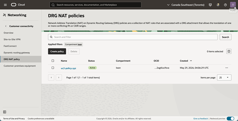
- Click on
uc2-policy-yyzand click on the Attachments tab. - Click on the Associate attachments button, select DRG Attachment for RPC: uc2-rpc-yyz and confirm.
- Notice that the RPC attachment is listed, together with its DRG route table
uc2-drgrt-rpc-yyz.
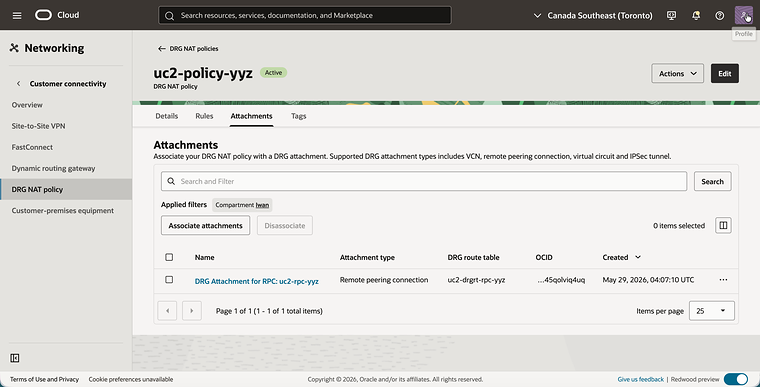
Both regions are now fully prepared. The routing is in place and both RPC attachments have a NAT policy. The only thing missing is the rules, and that is where the two options differ.
Step 07: Configure the NAT rules, option 1: a single rule in one region
In the first option all the translation is done in Montreal. The policy in Montreal gets one rule that translates source and destination, and the policy in Toronto stays empty.
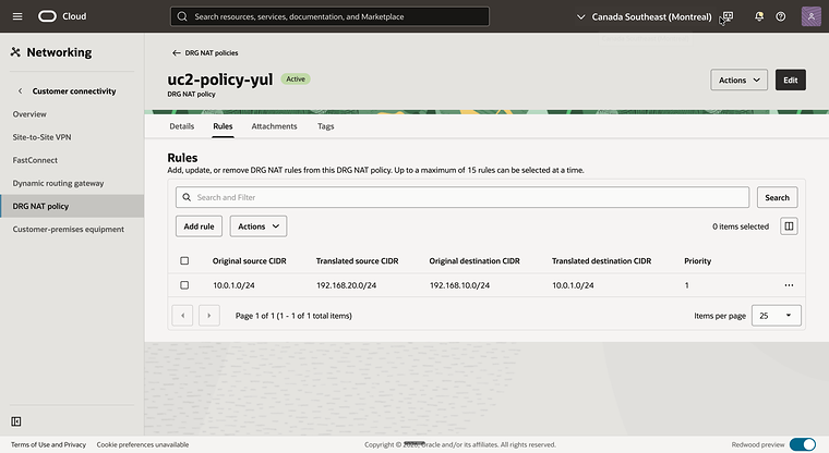
The rule sits on the RPC attachment in Montreal, so it is written for traffic that arrives from Toronto:
| Original | Translated | Meaning | |
|---|---|---|---|
| Source | 10.0.1.0/24 |
192.168.20.0/24 |
The real addresses of Toronto are presented in Montreal as 192.168.20.0/24. |
| Destination | 192.168.10.0/24 |
10.0.1.0/24 |
The shadow CIDR of Montreal is replaced with the real CIDR of Montreal. |
- Select the Canada Southeast (Montreal) region and open the DRG NAT policy
uc2-policy-yul. - Click on the Rules tab and click on the Add rule button.
- Add a rule with the following values:
- Priority:
1 - Original source CIDR:
10.0.1.0/24 - Translated source CIDR:
192.168.20.0/24 - Original destination CIDR:
192.168.10.0/24 - Translated destination CIDR:
10.0.1.0/24
- Priority:
- Notice that the rule is listed on the Rules tab.
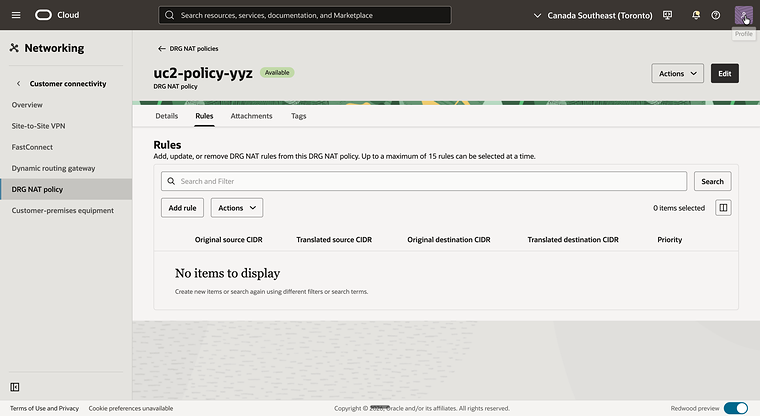
- Select the Canada Southeast (Toronto) region and open the DRG NAT policy
uc2-policy-yyz. - Click on the Rules tab.
- Notice that this policy has no rules.
This is what happens to a ping from uc2-inst-yyz in Toronto to uc2-inst-yul in Montreal:
| Where | Source | Destination | What happens |
|---|---|---|---|
Leaves uc2-inst-yyz |
10.0.1.152 |
192.168.10.121 |
The route table uc2-rt-yyz sends 192.168.10.0/24 to the DRG. |
| DRG in Toronto | 10.0.1.152 |
192.168.10.121 |
uc2-drgrt-vcn-yyz sends 192.168.10.0/24 to the RPC. No rules, so nothing is translated. |
| Enters the DRG in Montreal on the RPC attachment | 192.168.20.152 |
10.0.1.121 |
The rule in uc2-policy-yul translates source and destination. |
Route lookup in uc2-drgrt-rpc-yul |
192.168.20.152 |
10.0.1.121 |
10.0.1.0/24 points to uc2-att-vcn-yul. |
And this is the reply:
| Where | Source | Destination | What happens |
|---|---|---|---|
Leaves uc2-inst-yul |
10.0.1.121 |
192.168.20.152 |
The route table uc2-rt-yul sends 192.168.20.0/24 to the DRG. |
Route lookup in uc2-drgrt-vcn-yul |
10.0.1.121 |
192.168.20.152 |
192.168.20.0/24 points to the RPC. |
| Leaves the DRG in Montreal on the RPC attachment | 192.168.10.121 |
10.0.1.152 |
The DRG applies the reverse of the rule in uc2-policy-yul. |
| DRG in Toronto | 192.168.10.121 |
10.0.1.152 |
uc2-drgrt-rpc-yyz sends 10.0.1.0/24 to uc2-att-vcn-yyz. |
The last octet of an address is preserved by the 1:1 translation, which tells you which address to ping:
| Instance | Real IP address | Address to use from the other region |
|---|---|---|
uc2-inst-yul |
10.0.1.121 |
192.168.10.121 |
uc2-inst-yyz |
10.0.1.152 |
192.168.20.152 |
- Connect to
uc2-inst-yulwith SSH. - Run
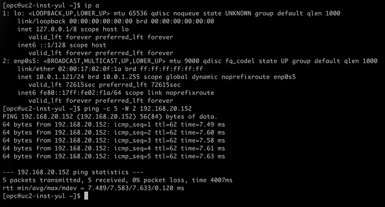
ip aand notice that the instance has the IP address10.0.1.121. - Run
ping -c 5 -W 2 192.168.20.152to ping the shadow address ofuc2-inst-yyz. - Notice that all five packets are answered.
- Connect to
uc2-inst-yyzwith SSH. - Run
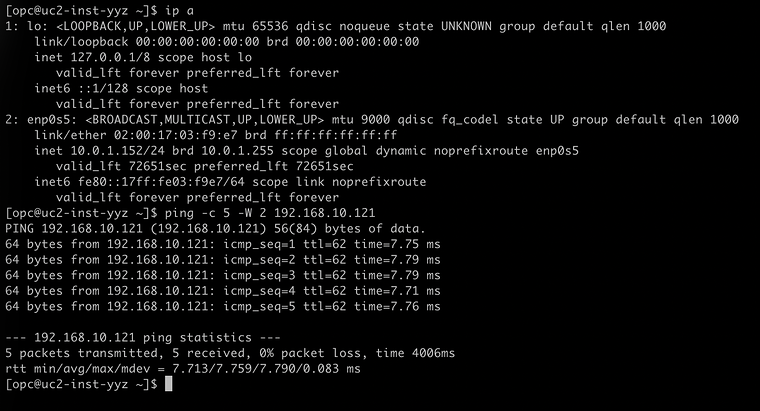
ip aand notice that the instance has the IP address10.0.1.152. - Run
ping -c 5 -W 2 192.168.10.121to ping the shadow address ofuc2-inst-yul. - Notice that all five packets are answered.
Step 08: Configure the NAT rules, option 2: a rule in each region
In the second option each region is responsible for its own shadow CIDR. Both policies get one rule, and both rules only translate the destination.
Each rule is again written for traffic that arrives from the other region:
| Policy | Original destination | Translated destination | Meaning |
|---|---|---|---|
uc2-policy-yul |
192.168.10.0/24 |
10.0.1.0/24 |
Traffic for the shadow CIDR of Montreal is delivered to the real CIDR of Montreal. |
uc2-policy-yyz |
192.168.20.0/24 |
10.0.1.0/24 |
Traffic for the shadow CIDR of Toronto is delivered to the real CIDR of Toronto. |
There is no source NAT rule, and none is needed. The reverse translation that the DRG applies to traffic leaving through the RPC attachment does that work: when a packet from 10.0.1.121 leaves Montreal, the reverse of the Montreal rule turns its source into 192.168.10.121.
- Select the Canada Southeast (Montreal) region and open the DRG NAT policy
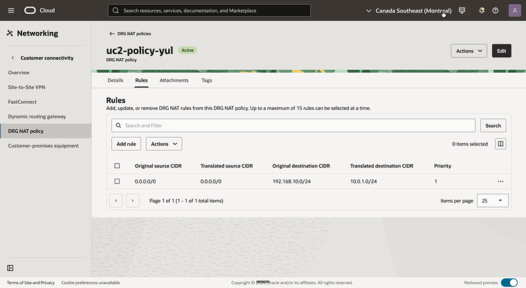
uc2-policy-yul. - Click on the Rules tab, remove the rule from option 1 and click on the Add rule button.
- Add a rule with the following values:
- Priority:
1 - Original source CIDR: leave empty
- Translated source CIDR: leave empty
- Original destination CIDR:
192.168.10.0/24 - Translated destination CIDR:
10.0.1.0/24
- Priority:
- Notice that the rule is listed on the Rules tab. The source columns show
0.0.0.0/0, which means that the rule matches any source and does not translate it.
- Select the Canada Southeast (Toronto) region and open the DRG NAT policy
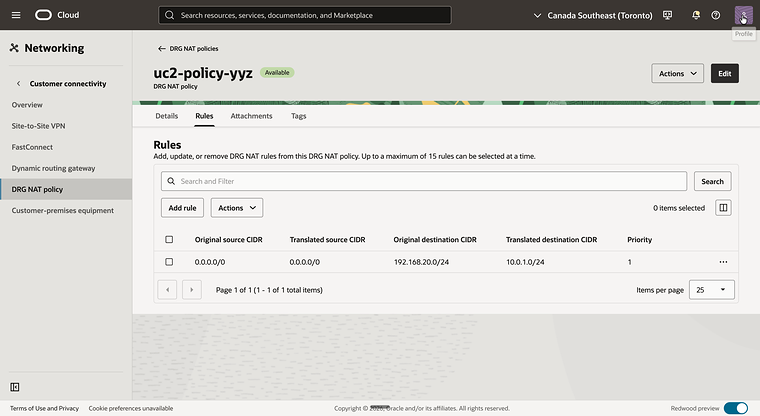
uc2-policy-yyz. - Click on the Rules tab and click on the Add rule button.
- Add a rule with the following values:
- Priority:
1 - Original source CIDR: leave empty
- Translated source CIDR: leave empty
- Original destination CIDR:
192.168.20.0/24 - Translated destination CIDR:
10.0.1.0/24
- Priority:
- Notice that the rule is listed on the Rules tab.
This is what happens to a ping from uc2-inst-yul in Montreal to uc2-inst-yyz in Toronto:
| Where | Source | Destination | What happens |
|---|---|---|---|
Leaves uc2-inst-yul |
10.0.1.121 |
192.168.20.152 |
The route table uc2-rt-yul sends 192.168.20.0/24 to the DRG. |
Route lookup in uc2-drgrt-vcn-yul |
10.0.1.121 |
192.168.20.152 |
192.168.20.0/24 points to the RPC. |
| Leaves the DRG in Montreal on the RPC attachment | 192.168.10.121 |
192.168.20.152 |
The DRG applies the reverse of the rule in uc2-policy-yul to the source. |
| Enters the DRG in Toronto on the RPC attachment | 192.168.10.121 |
10.0.1.152 |
The rule in uc2-policy-yyz translates the destination. |
Route lookup in uc2-drgrt-rpc-yyz |
192.168.10.121 |
10.0.1.152 |
10.0.1.0/24 points to uc2-att-vcn-yyz. |
Between the two regions the packet carries shadow addresses only. The real 10.0.1.x addresses never leave their own region. The reply follows the same steps in the other direction.
- Connect to
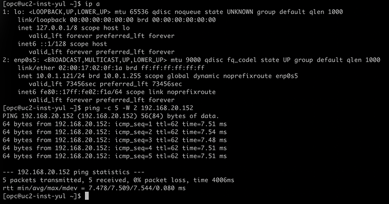
uc2-inst-yulwith SSH. - Run
ip aand notice that the instance has the IP address10.0.1.121. - Run
ping -c 5 -W 2 192.168.20.152to ping the shadow address ofuc2-inst-yyz. - Notice that all five packets are answered.
- Connect to
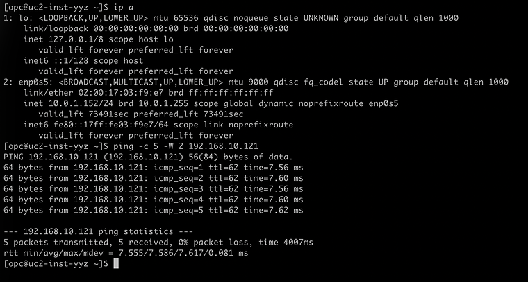
uc2-inst-yyzwith SSH. - Run
ip aand notice that the instance has the IP address10.0.1.152. - Run
ping -c 5 -W 2 192.168.10.121to ping the shadow address ofuc2-inst-yul. - Notice that all five packets are answered.
Conclusion
Two VCNs with the same subnet CIDR, in two different regions, now communicate privately over a remote peering connection. Neither VCN was re-addressed and there is no firewall or NAT appliance in the path. The translation is done by the DRGs on the RPC attachments.
Placing the policy on the RPC attachment instead of the VCN attachment changes where things happen. The DRG route table of the VCN attachment routes on the shadow CIDR, because nothing has been translated yet when the packet comes in from the VCN. The DRG route table of the RPC attachment routes on the real CIDR, because the packet has been translated on its way in. And because the policy sits on the link between the regions, it covers every VCN behind the DRG without touching the VCN attachments.
The two rule options lead to the same result for the instances. A single rule in one region keeps all the configuration in one place, and a destination NAT rule in each region gives a symmetrical design in which the real addresses stay inside their own region. In NAT on DRG Part 3: Overlapping CIDRs between OCI and On-Premisesthe remote side is no longer an OCI region but an on-premises network behind an IPSec tunnel.
Related articles