VMware Cloud Director Basics with NSX-T: Difference between revisions
m (clean up) |
|||
| Line 58: | Line 58: | ||
There are plenty of good articles that will show you how to deploy the VMware Cloud Director appliance like [https://captainvops.com/2020/04/09/deploying-vcloud-director-v10-appliance/ this one] or [https://www.vxpert.in/vmware-vcloud-director-standalone-installation/ this one]. | There are plenty of good articles that will show you how to deploy the VMware Cloud Director appliance like [https://captainvops.com/2020/04/09/deploying-vcloud-director-v10-appliance/ this one] or [https://www.vxpert.in/vmware-vcloud-director-standalone-installation/ this one]. | ||
=STEP | =STEP 1» NSX-T configuration= | ||
The deployment of NSX-T is also out of this article's scope, but it is important to know how to configure the VRF enabled Tier-0 Gateways. | The deployment of NSX-T is also out of this article's scope, but it is important to know how to configure the VRF enabled Tier-0 Gateways. | ||
Revision as of 16:41, 17 March 2024
This article will explain how you can integrate NSX-T into VMware Cloud Director to provide Network and Security capabilities across different tenants. To integrate NSX-T with VMware Cloud Director, you also need to know a bit about VMware Cloud Director and how it is installed, configured, and typical use-cases.
Software Versions used in this article
| Software | Version |
|---|---|
| vCenter Server | 7.0.1 (17005016) |
| ESXi | 7.0.1 (16850804) |
| NSX-T | 3.1 |
| Cloud Director | 10.2 |
Configuration Steps
- STEP 1) NSX-T configuration
- STEP 2) Add vCenter Server Instances to VMware Cloud Director
- STEP 3) Add NSX-T Manager to VMware Cloud Director
- STEP 4) Create Network Pools
- STEP 5) Create External Networks (per tenant)
- STEP 6) Create Provider VDCs
- STEP 7) Create Organization and Organization VDCs (per tenant)
- STEP 8) Create Edge Gateways (per tenant)
- STEP 9) Create an Organization Virtual Data Center Network
- STEP 10) Share Edge Gateways between Organization VDCs (of the same tenant)
- STEP 11) Verify the Data Center Group Networks
- STEP 12) Create Provider VDCs VM Placement Policies
- STEP 13) Create several VMs that will simulate an application
- STEP 14) Configure Distributed Firewall Rules on the applications
vSphere Deployment specifications
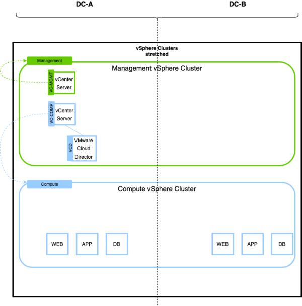
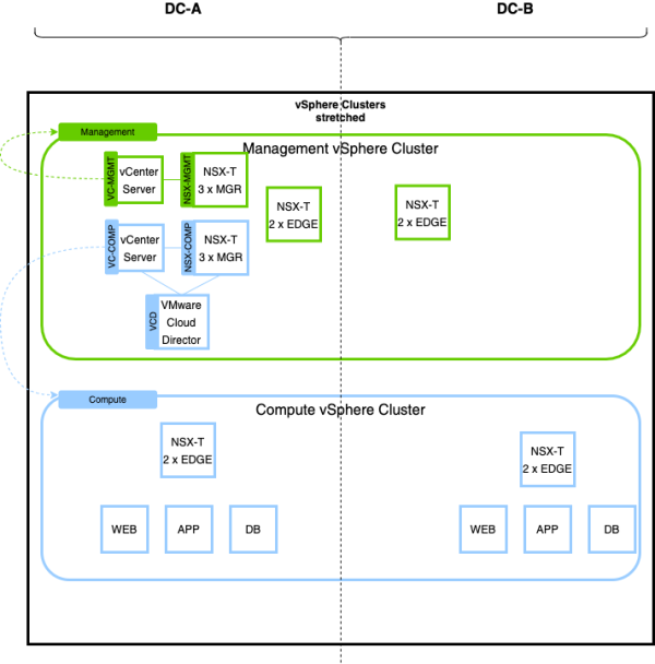
In this article, I will be working with a stretched vSphere (METRO) cluster, where I will have two Data Center Sites where all the vSphere Clusters are stretched across these sites. One vCenter Server will "manage" the management hosts (in the management vSphere Cluster) of the first and second Data Center. Another vCenter Server will "manage" the compute hosts (in the compute vSphere Cluster) of the first and second Data Center.
Because NSX-T will also be installed on the Management Cluster, we don't want this to interfere or impact the compute cluster in case of errors/mistakes.
NSX-T Deployment specifications
Two NSX-T Manager Clusters will be deployed. One NSX-T Manager will provide network and security services to the management vSphere Cluster, and the other one will provide network and security services to the compute vSphere Cluster.
In this article, we will only work with the NSX-T environment that is working together with the compute cluster.
VMware Cloud Director deployment
The deployment of the VMware Cloud Director appliance is out of scope for this article. There are plenty of good articles that will show you how to deploy the VMware Cloud Director appliance like this one or this one.
STEP 1» NSX-T configuration
The deployment of NSX-T is also out of this article's scope, but it is important to know how to configure the VRF enabled Tier-0 Gateways. There are plenty of good articles that will show you how to deploy NSX-T like this one.
Configure a Tier–0 Gateway with two VRF enabled Gateways
I have written an article on how to deploy VRF enabled Tier-0 Gateways here.
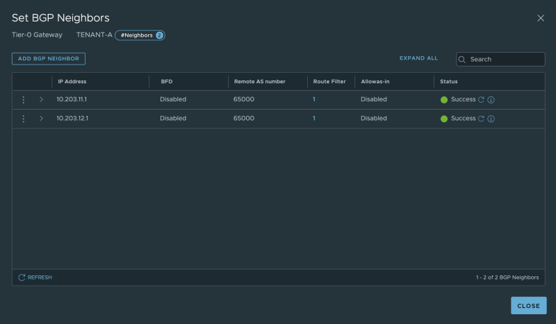
You cn see my configured VRF enabled Tier-0 Gateways here:
My dedicated BGP neighbour configuration for Tenant-A:
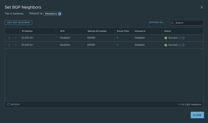
My dedicated BGP neighbor configuration for Tenant-B:
On the "physical routing" side, the BGP neighbors are also active. The yellow marked output below is dedicated to Tenant-A, and the green is dedicated to Tenant-B.
vyos@Pod-100-Router:~$ show ip bgp summary

IPv4 Unicast Summary:
BGP router identifier 10.203.100.1, local AS number 65000 vrf-id 0
BGP table version 155
RIB entries 24, using 4416 bytes of memory
Peers 12, using 245 KiB of memory

Neighbor        V         AS MsgRcvd MsgSent   TblVer  InQ OutQ  Up/Down State/PfxRcd
root ##y##10.203.11.2     4      65001    8027    8042        0    0    0 02:07:12            5
root ##y##10.203.11.3     4      65001    8028    8042        0    0    0 02:07:22            5
root ##y##10.203.12.2     4      65001    8027    8041        0    0    0 02:07:12            5
root ##y##10.203.12.3     4      65001    8028    8042        0    0    0 02:07:21            5
root ##g##10.203.13.2     4      65001    8013    8035        0    0    0 3d01h04m            0
root ##g##10.203.13.3     4      65001    8012    8034        0    0    0 3d01h38m            0
root ##g##10.203.14.2     4      65001    8012    8032        0    0    0 3d01h04m            0
root ##g##10.203.14.3     4      65001    8012    8031        0    0    0 3d01h38m            0
10.203.106.2    4      65001   27854   27860        0    0    0 3d01h04m            8
10.203.106.3    4      65001   27841   27857        0    0    0 3d01h38m            8
10.203.107.2    4      65001   27861   27870        0    0    0 3d01h04m            8
10.203.107.3    4      65001   27848   27866        0    0    0 3d01h38m            8

Total number of neighbors 12
vyos@Pod-100-Router:~$
VMware Cloud Director configuration
Before we can use the NSX-T network and security services, we need to configure some basic things that will be explained below.
Log in to VMware Cloud Director:
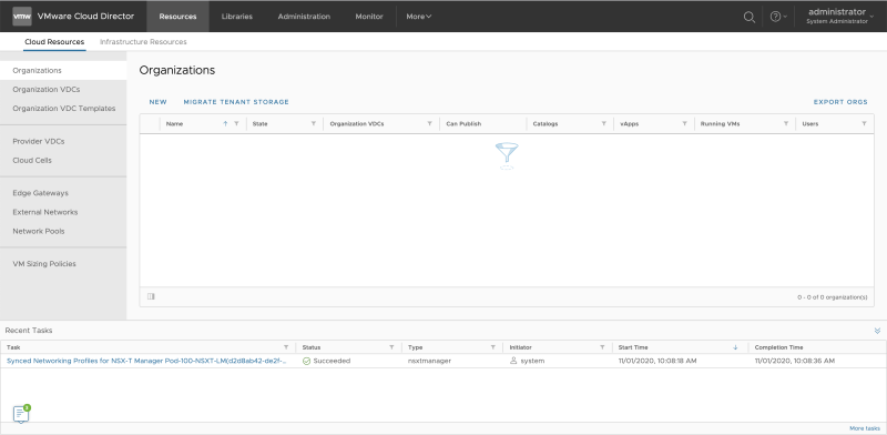
This is the screen when you log in to a blank VMware Cloud Director:
STEP 2» Add vCenter Server Instances to VMware Cloud Director
Click on "Infrastructure Resources >> vCenter Server Instances " to add a vCenter Server:
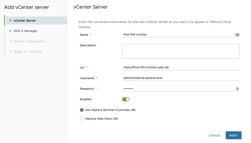
Add the vCenter Server details:
As I don't have NSX-v I will disable this as I don't want to configure any NSX-v settings:
I an not enabling "Tenant access" or want to "generate proxies":
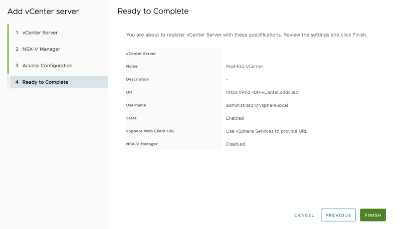
Review the summary screen:
The vCenter Server is successfully added to Cloud Director:
STEP 3» Add NSX–T Manager to VMware Cloud Director
Click on "Infrastructure Resources >> NSX-T Managers" to add an NSX-T Manager:
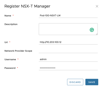
Add the NSX-T Manager details:
The NSX-T Manager is successfully added to Cloud Director:
STEP 4» Create Network Pools
To make sure that Cloud Director can make use of the overlay networks that are offered by NSX-T, you need to configure a Network Pool:
Go to "Resources >> Network Pools" to add a new Network Pool:
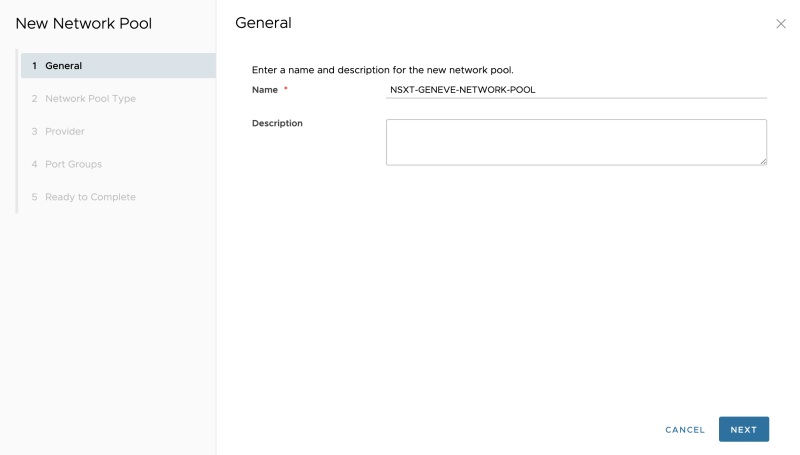
Specify a name:
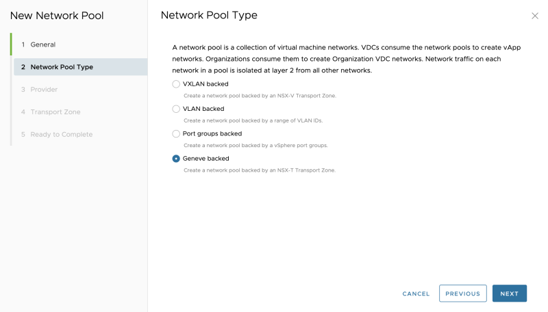
Select "Geneve backed":
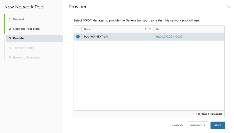
Select the NSX-T Manager:
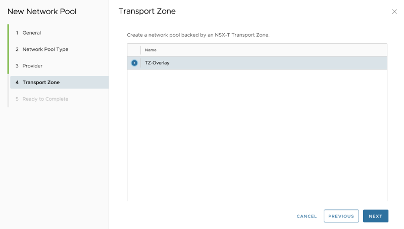
Select the "Transport Zone":
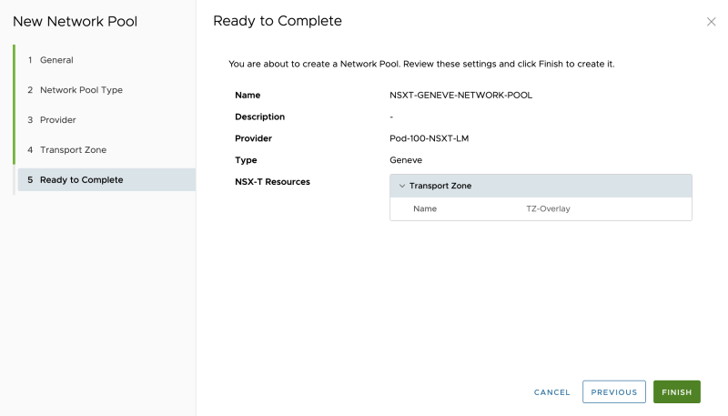
Review the summary:
The Network Pool is successfully added to Cloud Director:
STEP 5» Create External Networks 〈per tenant〉
It would be best if you created an external network per tenant. This network (pool) specifies the network (IP address Pool) that is going to be used between your Tier-0 (in my case, the VRF enabled Tier-0) and the (Tier-1) Tenant Edge (Gateways) that are going to be created. The "transit" network between the Tier-0 and Tier-1 Gateways.
Go to "Cloud Resources >> External Networks" to create an external network:
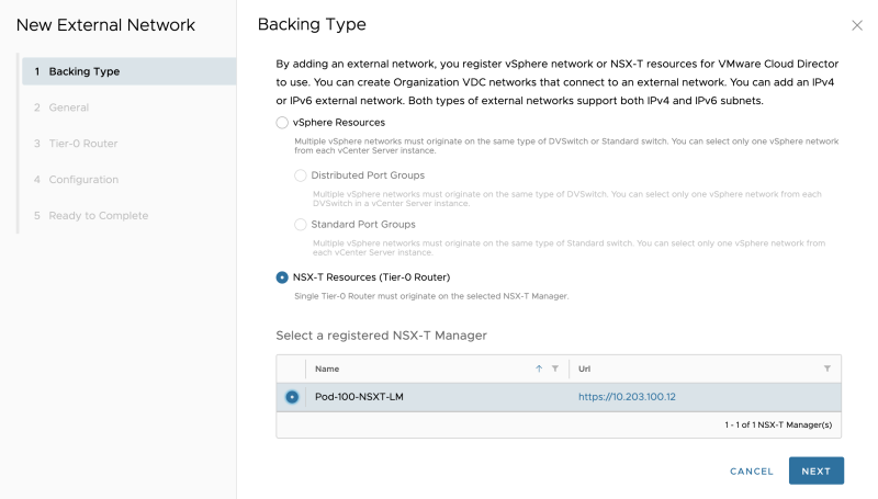
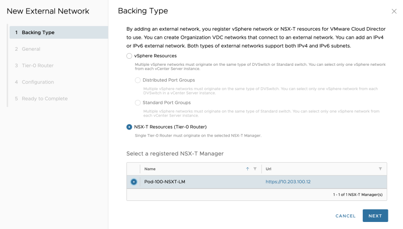
Select "NSX-T Resources":
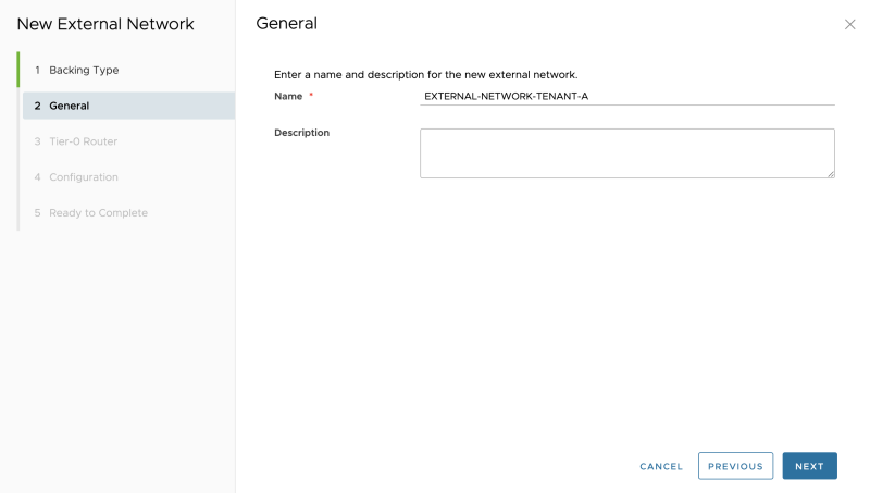
As this is an external network for my Tenant-A give it a name related to Tenant-A:
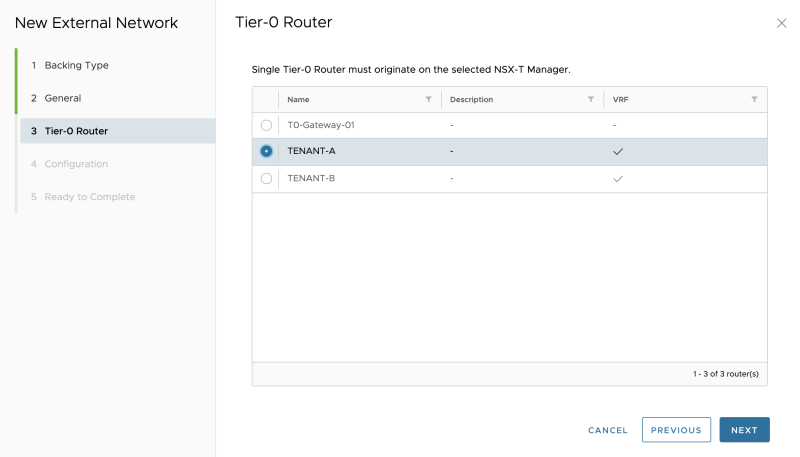
Select the Tenant-A VRF enabled Tier-0 Gateway:
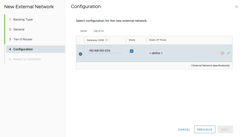
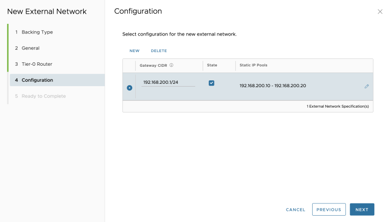
Specify a "gateway" IP address that will be configured on the downlink interface of the VRF enabled Tier-0 Gateway for Tenant-A:
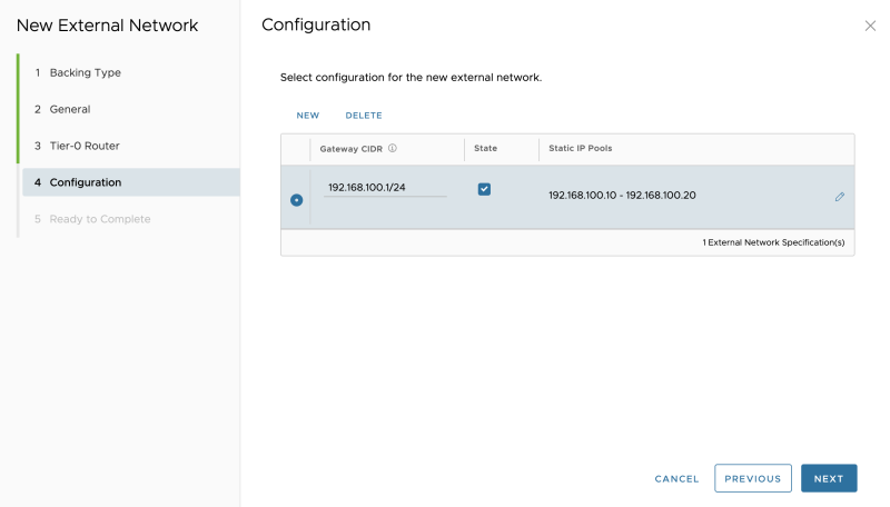
Specify a network pool, for the amount of the (Tier-1) Tenant Edge (Gateways)you are planning to add:
Verify if the pool is configured correctly:
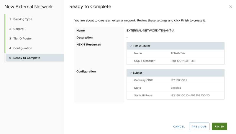
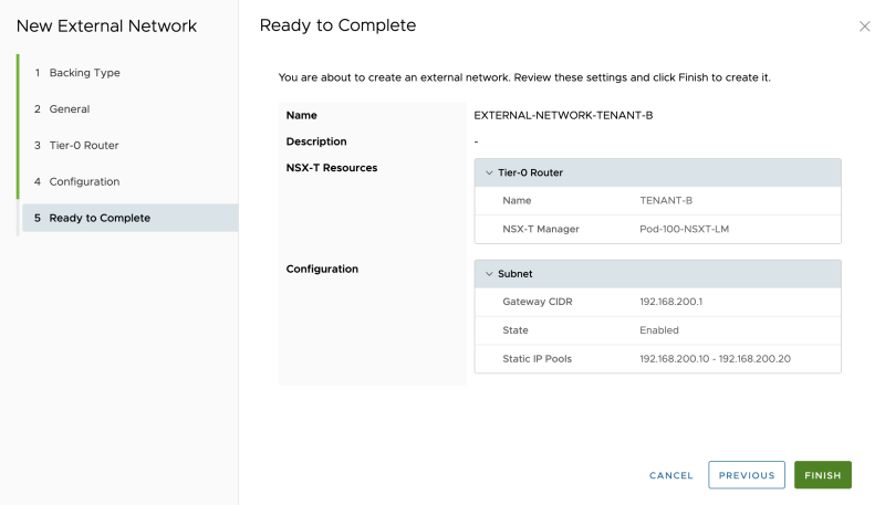
Review the summary:
The External Network for Tenant-A is successfully created:
Also, create an External Network for Tenant-B with like I did below:
Select "NSX-T Resources":
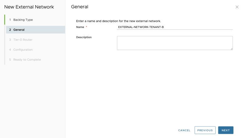
As this is an external network for my Tenant-B give it a name related to Tenant-B:
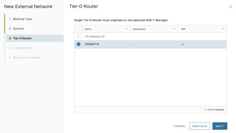
Select the Tenant-B VRF enabled Tier-0 Gateway:
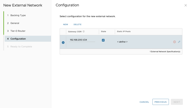
Specify a "gateway" IP address that will be configured on the downlink interface of the VRF enabled Tier-0 Gateway for Tenant-B:
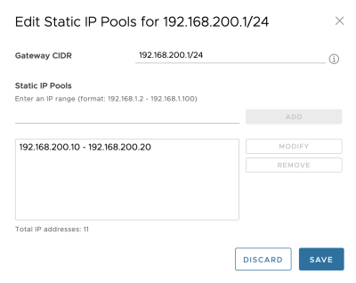
Specify a network pool, for the amount of the (Tier-1) Tenant Edge (Gateways)you are planning to add:
Verify if the pool is configured correctly:
Review the summary:
The External Network for Tenant-B is successfully created:
STEP 6» Create Provider VDCs
It would be best if you created a Provider VCD.
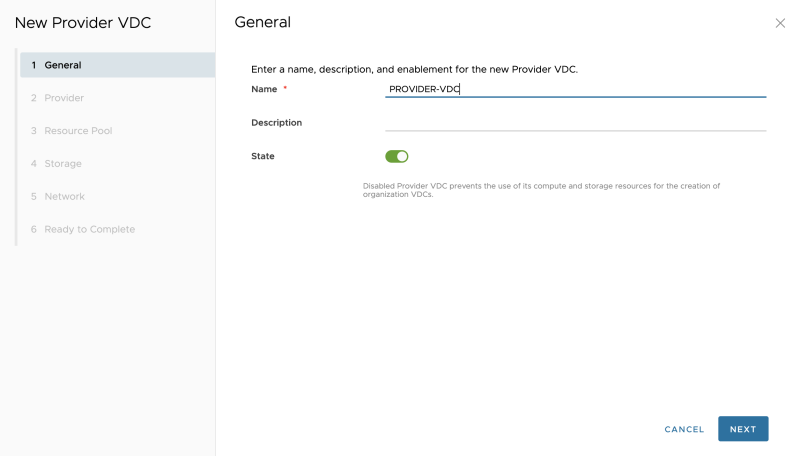
Go to "Cloud Resources >> Provider VDCs" to add a new Provider VCD:
Specify a name:
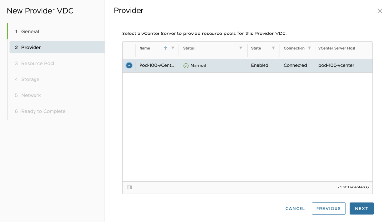
Select a vCenter Server:
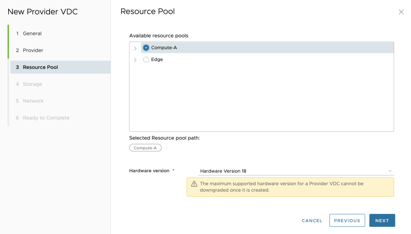
Select a Resource Pool (vSphere Cluster in my case):
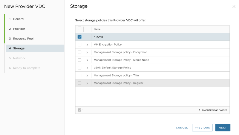
Select the Storage Policy:
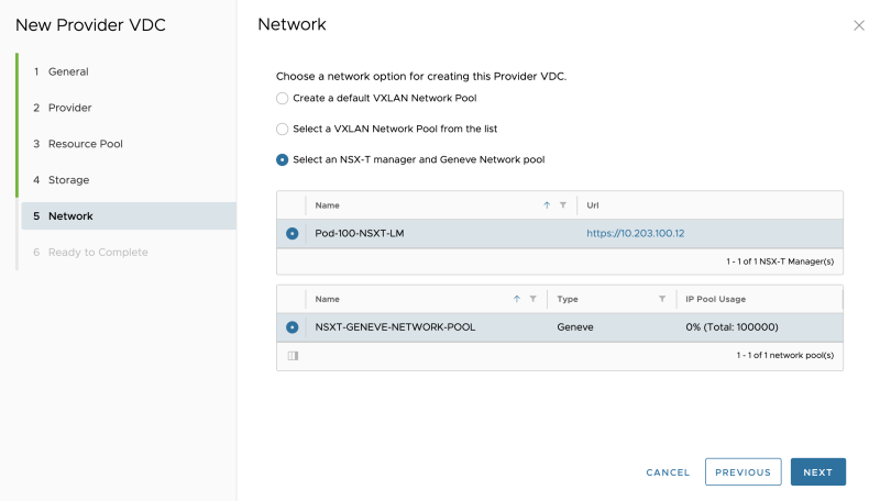
Select the NSX-T Manager and Network Pool:
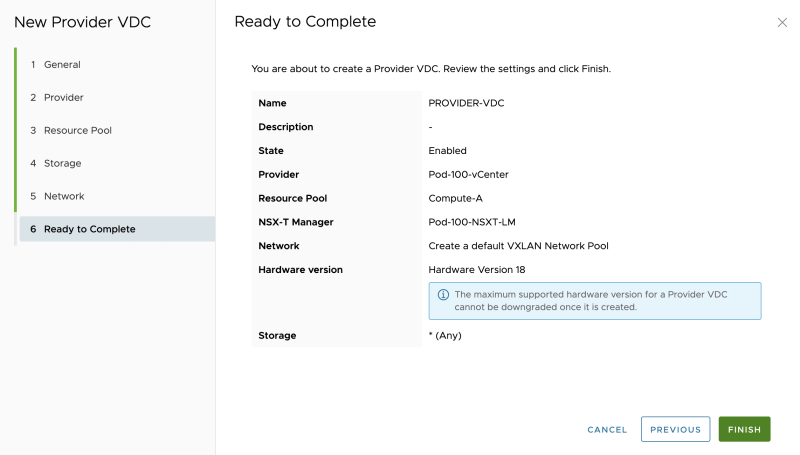
Review the summary:
The Provider VDC is now successfully added:
STEP 7» Create Organization and Organization VDCs 〈per tenant〉
You now need to Organization and Organization VDCs for each Tenant. I will create two Organizations one for each Tenant. Inside the Organization I will create multiple Organization VDCs per tenant:
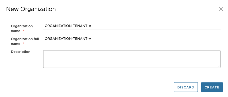
Go to "Cloud Resources >> Organizations" to add a new Organization:
Specify the Organization name for Tenant-A:
Review the Organization creation:
Specify the Organization name for Tenant-B:
Review the Organization creation:
Go to "Cloud Resources >> Organization VDCs" to add a new Organization VDC:
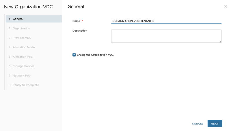
Specify a name for the first Organization VDC for Tenant-A. This Organization VDC will be bound to a vSphere STRETCHED cluster.
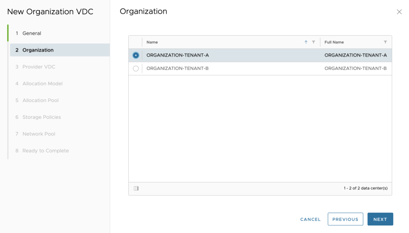
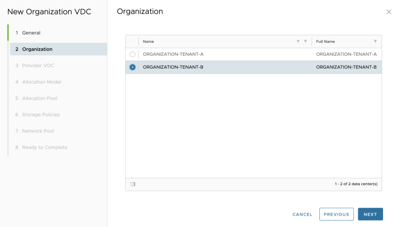
Select "Tenant-A" as the Organization:
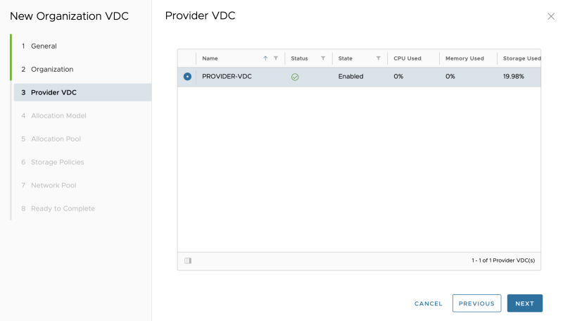
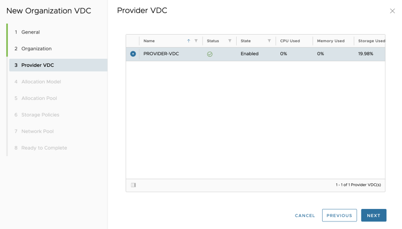
Select the Provider VDC:
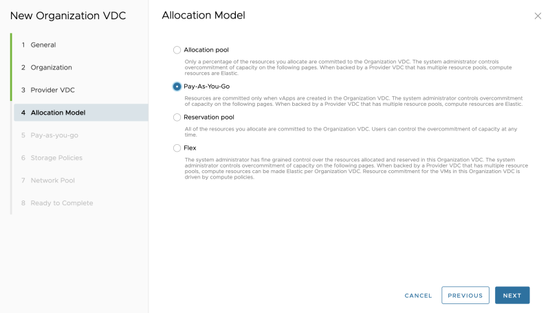
Select an allocation model (I am using Pay-as-you-go):
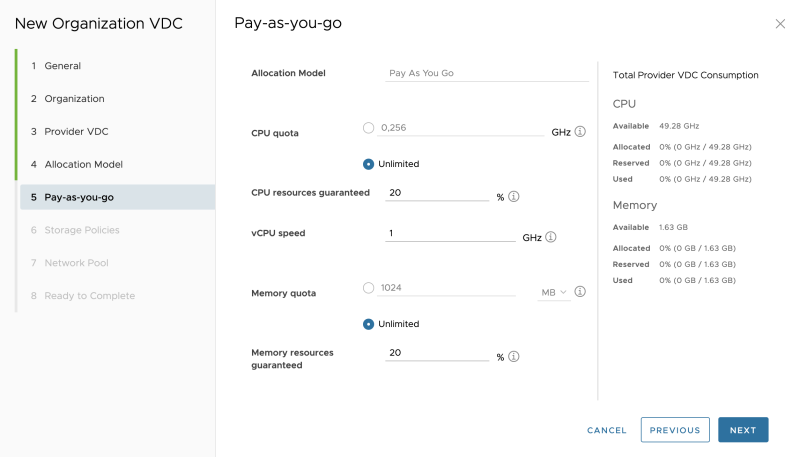
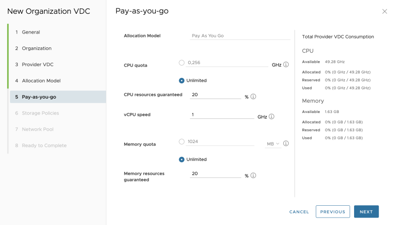
Specify the Pay-as-you-go details:
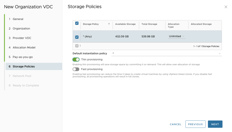
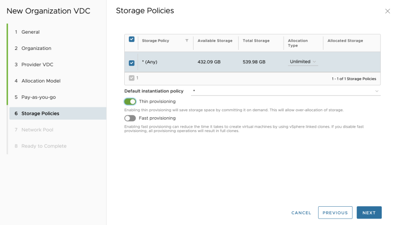
Select the Storage Policy and I enabled thin provisioning (as this is a nested lab):
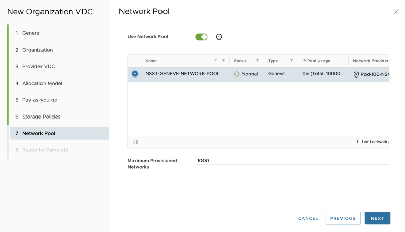
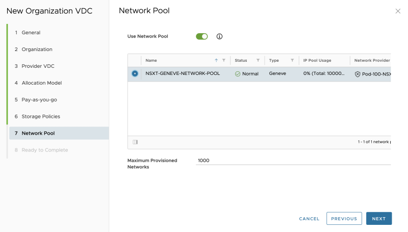
Select a network pool:
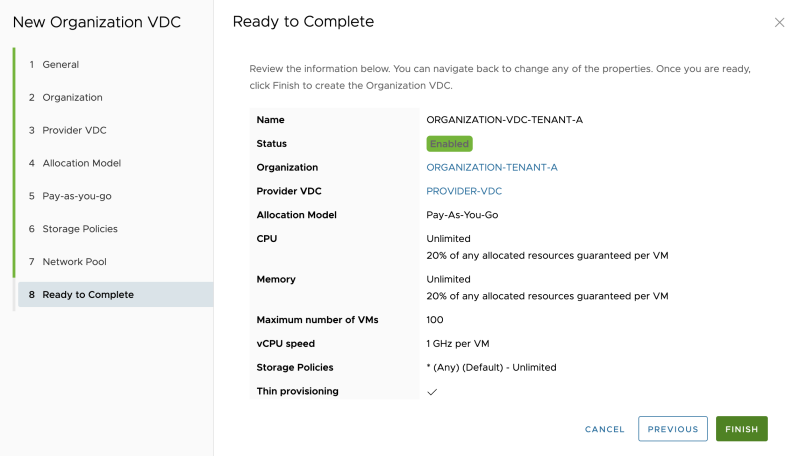
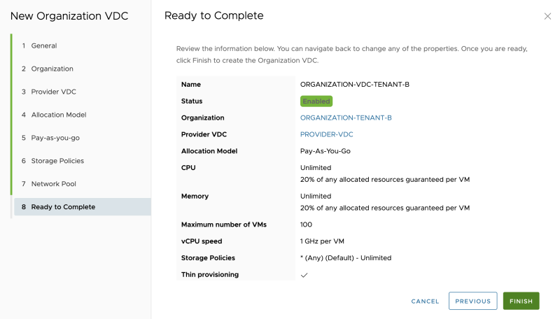
Review the summary:
The Organization VDC is now created:
Specify a name for the second Organization VDC for Tenant-B. This Organization VDC will be bound to a vSphere STRETCHED cluster.
Select "Tenant-B" as the Organization:
Select the Provider VDC:
Select an allocation model (I am using Pay-as-you-go):
Specify the Pay-as-you-go details:
Select the Storage Policy and I enabled thin provisioning (as this is a nested lab):
Select a network pool:
Review the summary (screenshot is not provided).
The Organization VDC is now created:
OPTIONAL: Create "the other "local/non-stretched" Organization VDCs the same way I did above:
STEP 8» Create Edge Gateways 〈per tenant〉
With Cloud Director, you can also create the Tier-1 Gateways that is bound to an Organization VDC. These are called "Edge Gateways" inside Cloud Director.
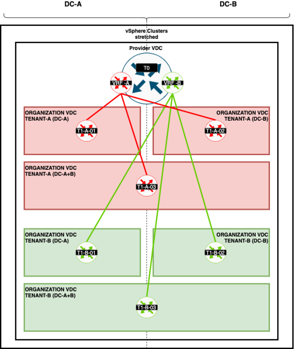
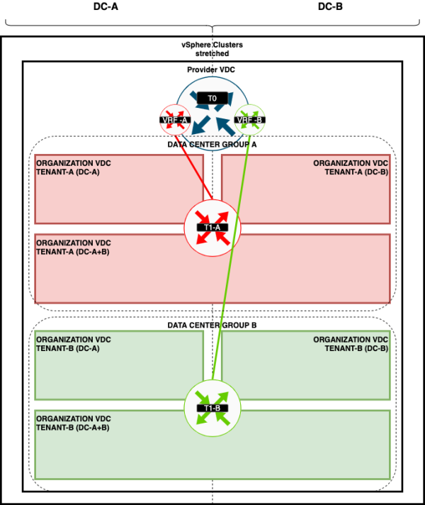
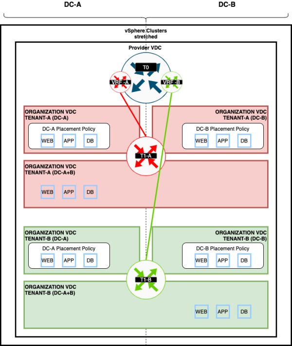
These Edge Gateways will be connected to the VRF enabled Tier-0 Gateways like I have illustrated on the figure below:
Go to "Cloud Resources >> Edge Gateways" to add a new Edge Gateway:
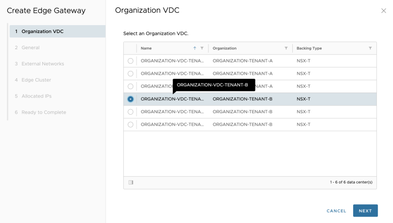
Select the Organization VDC where the Edge Gateway (Tier-1 Gateway) will be dedicated to:
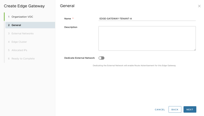
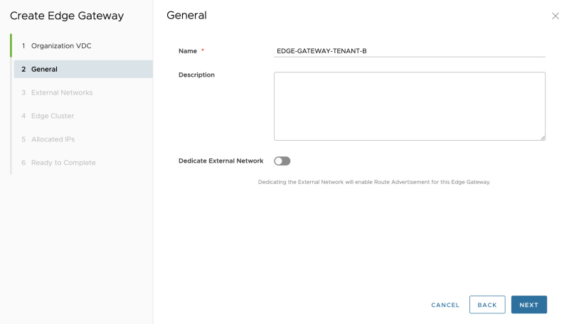
Specify a name:
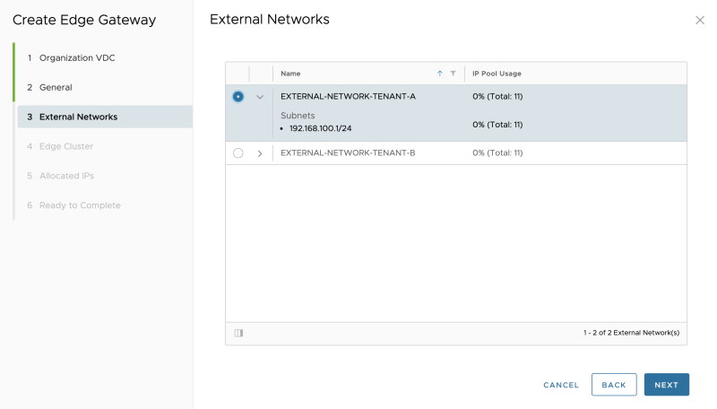
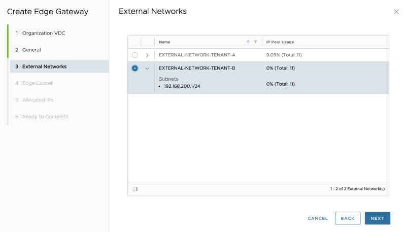
Select the (external)network pool that was created that is going to use as a "transit" subnet between the VRF enabled Tier-0 Gateways and the new Edge Gateway (Tier-1 Gateway):
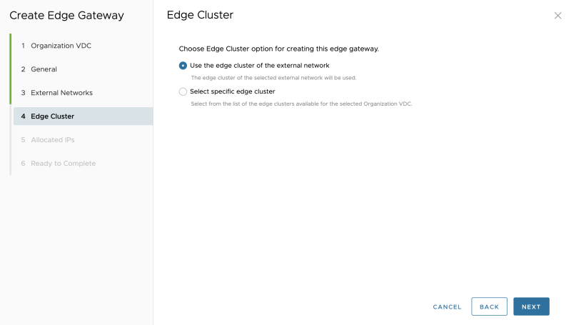
When you have a dedicated Edge Cluster for the Tier-1 Gateways, you can choose the second option; in my case, I am using the same Edge Cluster that I specified in the External Network.
This means that my Tier-0 Gateway and its corresponding VRF Enabled Gateways will all be configured on one Edge Transport Node Cluster:
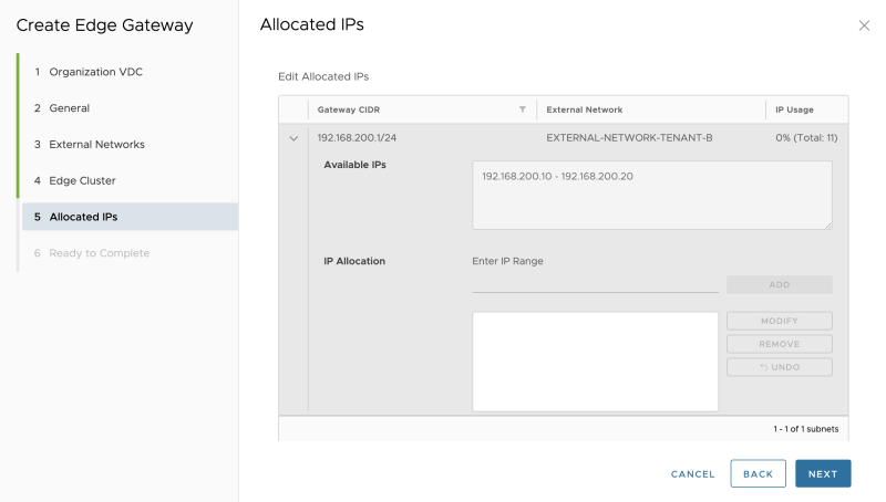
Leave the allocated IP addresses default:
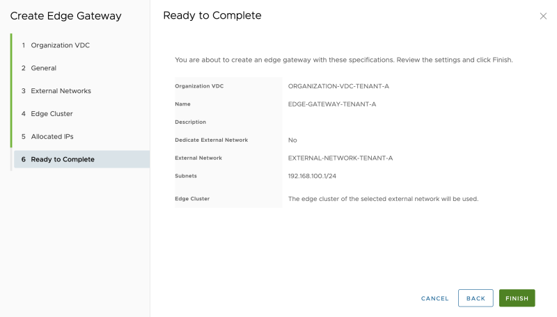
Review the summary:
The (first) Edge Gateway for Tenant-A is now created successfully:
Create another Edge Gateway for Tenant-B, Select the Organization VDC where the Edge Gateway (Tier-1 Gateway) will be dedicated to (This time dedicated to Tenant-B):
Specify a name:
Select the (external)network pool that was created that is going to use as a "transit" subnet between the VRF enabled Tier-0 Gateways and the new Edge Gateway (Tier-1 Gateway):
Select the NSX-T Edge (Transport Node) Cluster:
Leave the allocated IP addresses default:
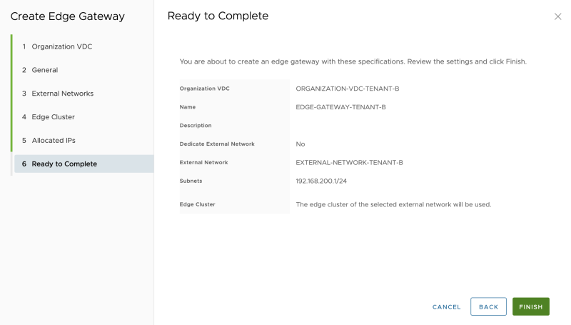
Review the summary:
The (second) Edge Gateway for Tenant-B is now created successfully:
When I take a sneak peek at the NSX-T Manager GUI, I can see that the Edge Gateways are created in the form of a Tier-1 Gateway on the NSX-T Manager:
STEP 9» Create an Organization Virtual Data Center Network
Now I will create the Guest Networks that I want to use that will be connected to the Edge Gateways (Tier-1 Gateways).
Go to "Cloud Resources >> Organization VDCs." Click on the arrow/link of the first Organization VDC to "impersonate" the Organisation Administrator for this specific tenant (ORGANIZATION-VDC-TENANT-A).
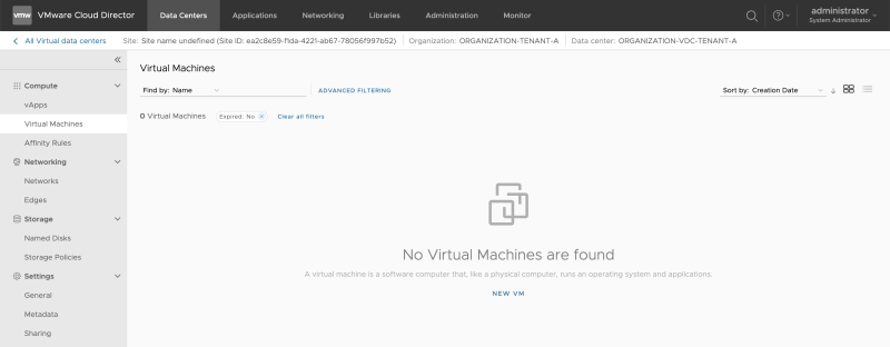
Now you are logged in as an Organisation Administrator for this specific tenant (ORGANIZATION-VDC-TENANT-A):
Go to "Data Centers >> Networks >> Networks" to add new Guest VM Networks:
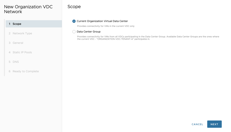
Select the "Scope." In my case, I am only creating a network (for now) that is bound to a specific VDC, and not shared across other VDCs (yet):
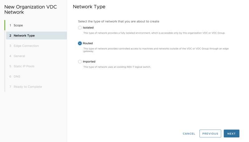
Select "Routed" as we are attaching this network to the created Edge Gateway (Tier-1 Gateway) for Tenant-A that we created in the previous steps:
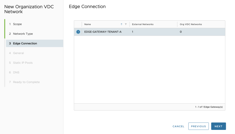
Select the Edge Gateway (Tier-1 Gateway) for Tenant-A that we created in the previous steps:
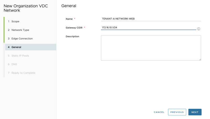
Specify the gateway address that will be configured on the Edge Gateways (Tier-1 Gateway) downlink. This will be the gateway IP address for your Guest VMs that will be connected to this network:
Specify a network pool for this network. This is Cloud Directors' internal IPAM tool to assign IP addresses to the Guest Virtual Machines when they are created on the network you are creating now:
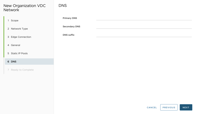
Specify DNS details, if you have any:
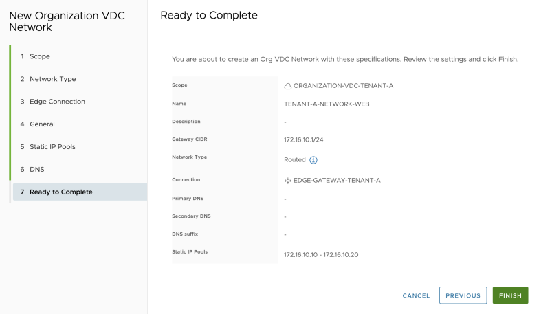
Review the summary:
Repeat the previous steps to also create the APP and DB networks for Tenant-A (ORGANIZATION-VDC-TENANT-A):
Repeat the previous steps to also create the WEB, APP and DB networks for Tenant-B (ORGANIZATION-VDC-TENANT-B):
When I look at the NSX-T GUI, I can now see that the "linked segments" on the Tier-1 Gateways have been increased to 3. this means that the networks we just created using Cloud Director have been added to NSX-T (as a Segment) and are attached to the Tier-1 Gateway:
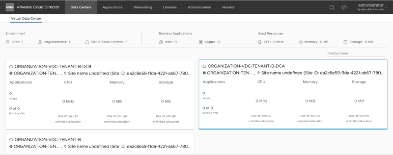
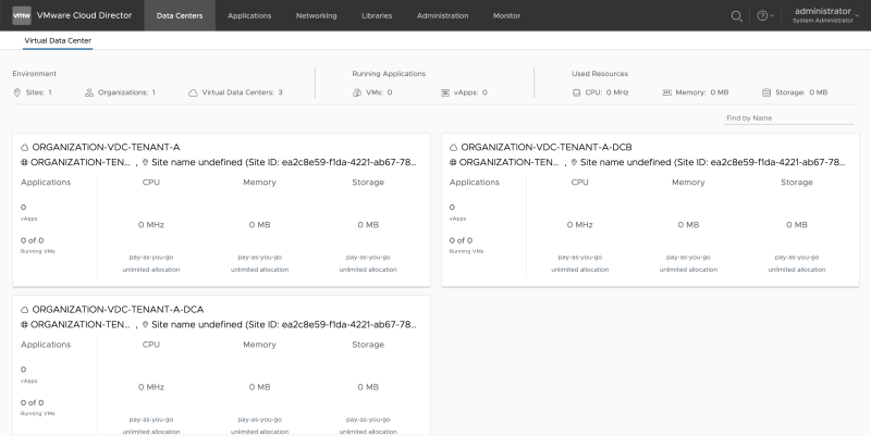
While being in "Organization Tenant mode, go to "Data Centers >> Virtual Datacenter" and click on another Organization VDC (ORGANIZATION-VDC-TENANT-A-DCA or ORGANIZATION-VDC-TENANT-A-DCB).
Go to "Data Centers >> Networking >> Networks," and review that this network section is empty as we have configured our networks in another Organization VDC (ORGANIZATION-VDC-TENANT-A-DCA or ORGANIZATION-VDC-TENANT-A-DCB).
To "share" the networks that I just created with another Organization VDC (the one that was just empty), I need to create a Data Center Group.
The figure below illustrates how this will look like:
Create Data Center Groups
Configure Compute Provider Scope
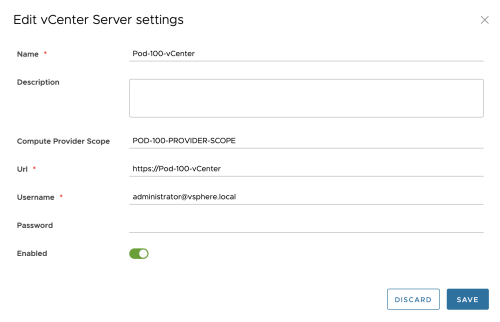
Before a Data Center Group can be configured, I need to specify a "Compute Provider Scope."
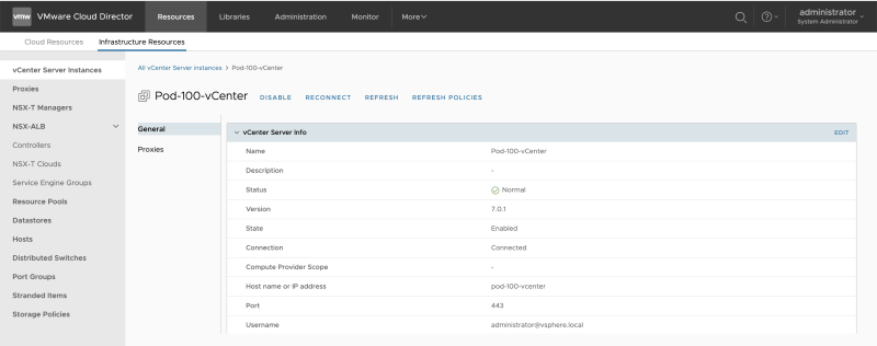
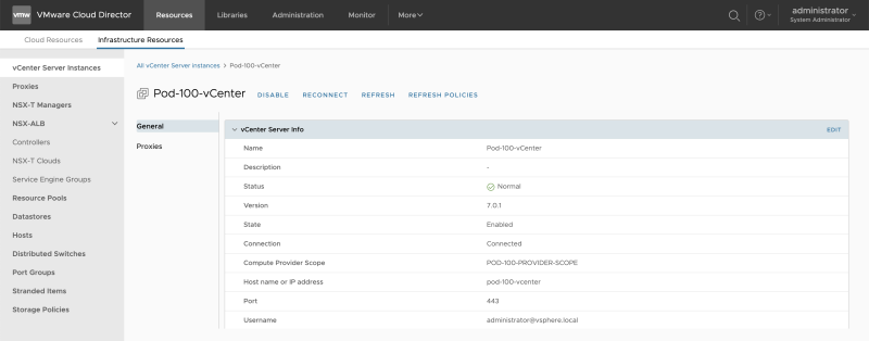
Go (back) to the Cloud Director administration panel and go to "Infrastructure Resources >> vCenter Server Instances " to edit the vCenter Server:
Configure the Compute Provider Scope:
Review the Compute Provider Scope:
Create Data Center Groups
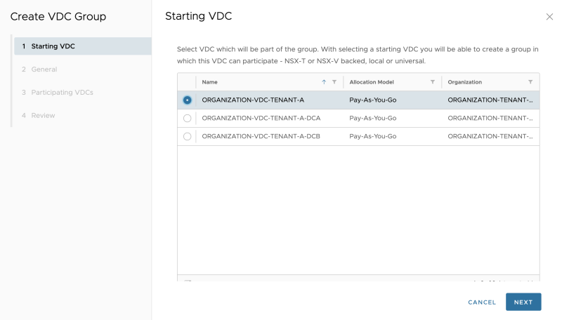
Go back to the "Organization VDC administration" screen and go to "Networking >> Data Center Groups" to add a Data Center Group:
Select the "primary" Organization VDC:
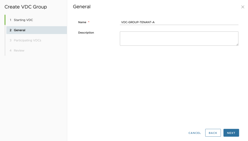
Give the Data Center Group a name:
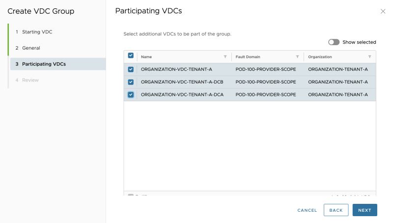
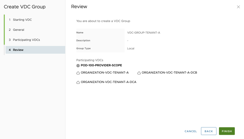
Select the remaining Organization VDCs that you want to form a group with:
Review the summary:
The new Data Center Group is successfully created:
Assign an Edge Gateway to a Data Center Group
Click on the Data Center group you have just created, and go to Edge Gateway. Select "Add Edge":
Select the Edge Gateway (Tier-1 Gateway) that is created before:
When you add the Edge Gateway to a Data Center Group, this means all the networks that were created on this Edge Gateway in another Organization VDC are now automatically added to the other Organization VDCs that are part of this Data Center Group
The Edge Gateaway is added to the Data Center Group successfully (for Tenant-A):
For Tenant-B you need to follow the same steps as above, but then you need to use the Tenant-B Organization VCDs and Edge Gateways with the below figure as a result:
STEP 11» Verify the Data Center Group Networks
Now its time to see if the networks that were created in the "ORGANIZATION-VDC-TENANT-A" VDC are also added to the "ORGANIZATION-VDC-TENANT-A-DCA" and "ORGANIZATION-VDC-TENANT-A-DCB" VCD:
Review the "ORGANIZATION-VDC-TENANT-A" networks:
Review the "ORGANIZATION-VDC-TENANT-A-DCA" networks:
Review the "ORGANIZATION-VDC-TENANT-A-DCB" networks:
STEP 12» Create Provider VDCs VM Placement Policies
When you look specifically at the "ORGANIZATION-VDC-TENANT-A" VDC, this is a VDC that is tied to a stretched vSphere Cluster.
When you want to place Virtual Machines on DC-A or DC-B, you can do two things:
- Use the "ORGANIZATION-VDC-TENANT-A-DCA" VDC (local to DC-A)
- Use the "ORGANIZATION-VDC-TENANT-A-DCB" VDC (local to DC-A)
- Use the "ORGANIZATION-VDC-TENANT-A" VDC (stretched between DC-A and DC-B) with the use of VM Placement Policies
How to achieve method #3, I will explain this in the section below.
This is also illustrated in the figure below:
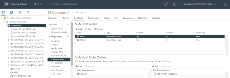
First, log in to the vCenter Server and go to the VM/Host Groups vSphere Cluster settings:
Create a Host Group 〈in vCenter Server〉
Create 2 host groups, one for DC-A and the other for DC-B and place the hosts corresponding to the correct site in the correct group:
Create a VM Group 〈in vCenter Server〉
Create 2 VM groups, one for DC-A and the other for DC-B and place the VMs corresponding to the correct site in the correct group:
Create a VM to Host Rule 〈in vCenter Server〉
Create a VM/Host rule, one for DC-A and the other for DC-B, and make sure that you specify that the VMs in the VM Group for DC-A must run on the Hosts in Host Group for DC-A. Do the same for DC-B.
When you have done this, go to "Infrastructure Resources >> vCenter Server Instances " and click on "Refresh" to make sure Cloud Director detects the Groups and Rules.
Create VM Placement Policies 〈in the Provider VDC〉
Go to "Cloud Resources >> Provider VDCs" to edit the Provider VCD:
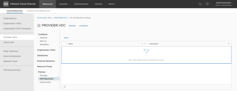
Go to "Cloud Resources >> Provider VDC >> PROVIDER-VDC >> Policies >> VM Placement" to add a new Placement Policy:
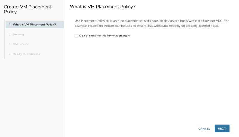
Leave this default and click next:
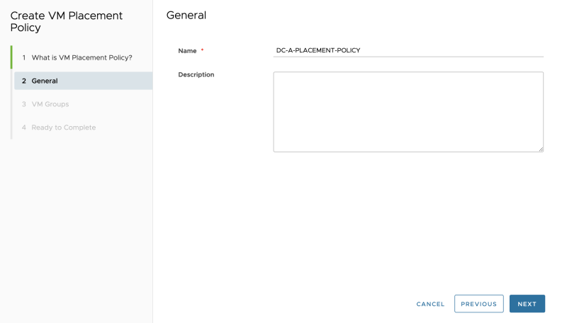
Specify a name:
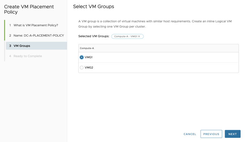
Select the "rule" you just created in vCenter Server corresponding to DC-A:
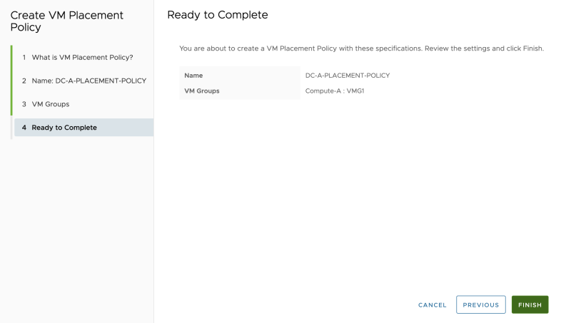
Review the summary:
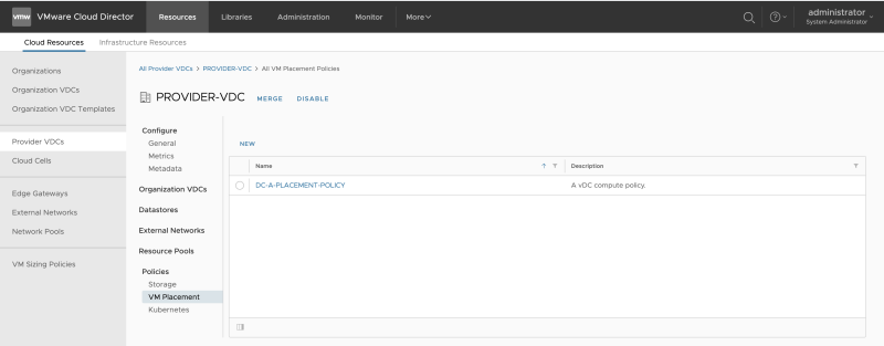
The Placement Policy for DC-A is created successfully:
Follow the same steps to create another Placement Policy for DC-B:
STEP 13» Create several VMs that will simulate an application
To test the networks you just added, you need to create Guest Virtual Machines. I have done this in the next section:
Create several VMs that will simulate an application 〈Web App and DB〉
I have pre-created a 3-Tier vAPP that was based on an OVF. This is out of scope for this article.
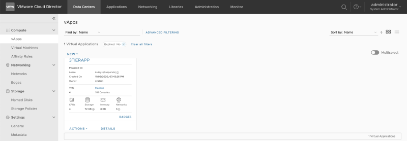
When you click on the vApp, you will see the networks that this vAPP is using.
Review the Network Diagram:
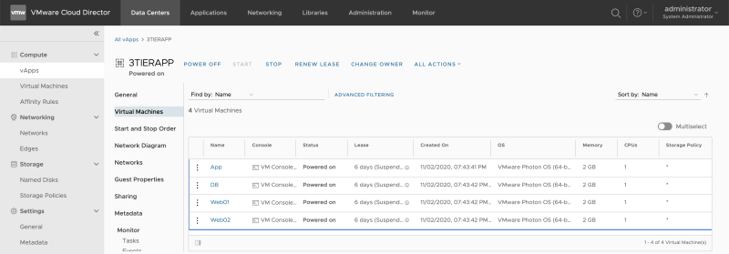
Review the Virtual Machines that are in the vAPP and select the first VM (Web01):
Verify the available networks:
Verify the NIC settings and select the created WEB network for the WEB01 Guest VM that is part of this vAPP.
Verify the NIC settings:
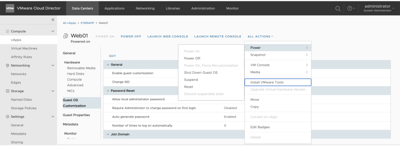
Make sure that VM Guest Customization is enabled. This is needed to make sure the IP address is assigned from the custom Cloud Director Pool.
When the VM is stopped, make sure you Power on the Guest VM using the "Force Recustomization" option.
STEP 14» Configure Distributed Firewall Rules on the applications
You can configure the "Distributed Firewall" within this Data Center Group.
Go to the "Organization VDC administration" screen (ORGANIZATION-VDC-TENANT-A) and go to "Networking >> Data Center Groups >> General."
You will see that by default, the "Distributed Firewall" is not active.
When you click on active, you activate this.
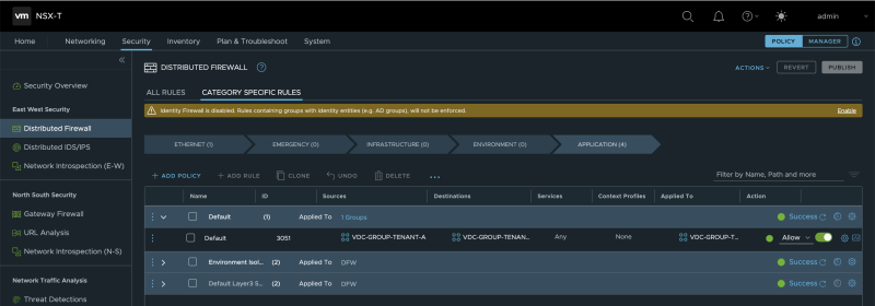
Once you have activated the Distributed Firewall, you will see in the NSX-T Manager GUI that a new Security Policy with a new Distributed Firewall Rule is created dedicated to the Data Center Group.
Lessons learned
Wenn playing around with Cloud Director and NSX-T, a few things are worth mentioning here.
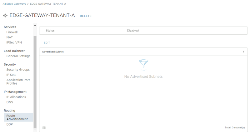
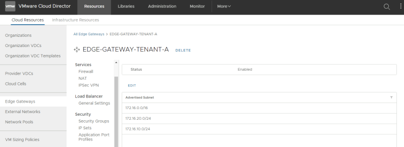
Configure Route advertisement on the Edge Gateway 〈Tier–1 Gateway〉 through VMware Cloud Director
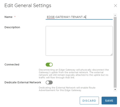
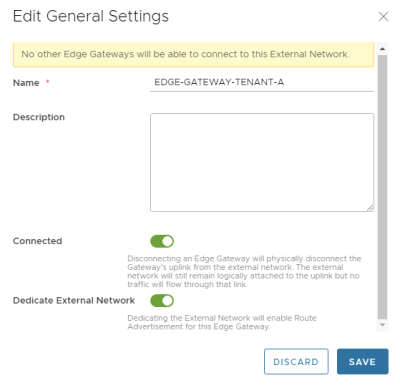
There is a setting that you can enable "Dedicate External Network" on the Edge Gateway (Tier-1 Gateway) you create.
When you enable this setting, you will configure "Routing Settings" on the Edge on the Edge Gateway (Tier-1 Gateway.
You can only enable this setting on ONE single Edge Gateway (Tier-1 Gateway. From a theoretical point of view, when network advertisement could be done on multiple Edge Gateways (Tier-1 Gateways), the same networks could be advertised, causing a routing conflict.
Once you enable "Dedicate External Network" you will see the additional routing sections:
I have configured three networks (172.16.10.0/24, 172.16.20.0/24, and 172.16.30.0/24) to be advertised.
We can verify this setting in the NSX-T Manager by looking at the corresponding Tier-1 Gateway routing settings.
An output of the routing table of the "external router" is provided below:
B>* 172.16.10.0/24 [20/0] via 10.203.11.2, eth1.11, 00:01:49
  *                       via 10.203.11.3, eth1.11, 00:01:49
  *                       via 10.203.12.2, eth1.12, 00:01:49
  *                       via 10.203.12.3, eth1.12, 00:01:49
B>* 172.16.20.0/24 [20/0] via 10.203.11.2, eth1.11, 00:00:46
  *                       via 10.203.11.3, eth1.11, 00:00:46
  *                       via 10.203.12.2, eth1.12, 00:00:46
  *                       via 10.203.12.3, eth1.12, 00:00:46
B>* 172.16.30.0/24 [20/0] via 10.203.11.2, eth1.11, 00:00:46
  *                       via 10.203.11.3, eth1.11, 00:00:46
  *                       via 10.203.12.2, eth1.12, 00:00:46
  *                       via 10.203.12.3, eth1.12, 00:00:46
Configure Edge Gateway Firewall 〈Tier–1 Gateway〉 through VMware Cloud Director
When you configure an Edge Gateway (Tier-1 Gateway) from Cloud Director, the default Gateway firewall setting is set to "DENY."
In the figure below I have changed this to "ALLOW":
Verify if the firewall rule is now set to allow:
