Configure NSX-T VRF Lite: Difference between revisions
m (Change span border color) |
m (Fixing TOC) |
||
| (One intermediate revision by one other user not shown) | |||
| Line 3: | Line 3: | ||
In this wiki article, I will show you how to configure VRF Lite using NSX-T with two separate tenants. | In this wiki article, I will show you how to configure VRF Lite using NSX-T with two separate tenants. | ||
=The Network Diagrams= | ==The Network Diagrams== | ||
==My starting point== | ==My starting point== | ||
| Line 19: | Line 19: | ||
<div style="clear:both"></div> | <div style="clear:both"></div> | ||
=The high | ==The high–level steps== | ||
In this wiki, the high level following steps will be discussed: | In this wiki, the high level following steps will be discussed: | ||
* STEP 1: Create a Parent Tier-0 Gateway | * STEP 1: Create a Parent Tier-0 Gateway | ||
| Line 36: | Line 36: | ||
* STEP 14: Configure Route leaking between the two tenants (Inter-VRF-Routing) | * STEP 14: Configure Route leaking between the two tenants (Inter-VRF-Routing) | ||
=The configuration steps= | ==The configuration steps== | ||
==STEP 1 | ==STEP 1{{fqm}} Create a Parent Tier–0 Gateway== | ||
I already preconfigured this part and here are the screenshots with the current configuration of the initial Parent Tier-0 Gateway. | I already preconfigured this part and here are the screenshots with the current configuration of the initial Parent Tier-0 Gateway. | ||
| Line 52: | Line 52: | ||
<span style="border:3px solid #f4c613;display: inline-block;">[[File:segment-127.png|800px]]</span> | <span style="border:3px solid #f4c613;display: inline-block;">[[File:segment-127.png|800px]]</span> | ||
===The Tier | ===The Tier–0 Parent Gateway=== | ||
This is the parent Tier-0 Gateway that was created that will initially be the "host" for theVRF enabled Tier-0 Gateways. | This is the parent Tier-0 Gateway that was created that will initially be the "host" for theVRF enabled Tier-0 Gateways. | ||
| Line 58: | Line 58: | ||
<span style="border:3px solid #f4c613;display: inline-block;">[[File:Parent-Tier-0-Gateway.png|800px]]</span> | <span style="border:3px solid #f4c613;display: inline-block;">[[File:Parent-Tier-0-Gateway.png|800px]]</span> | ||
===The uplink interfaces for the Tier | ===The uplink interfaces for the Tier–0 Parent Gateway=== | ||
On the parent Tier-0 Gateway, I needed to configure four uplinks in total, two uplink interfaces on the first Edge Transport Node, and two uplink interfaces on the second Edge Transport Node. | On the parent Tier-0 Gateway, I needed to configure four uplinks in total, two uplink interfaces on the first Edge Transport Node, and two uplink interfaces on the second Edge Transport Node. | ||
| Line 70: | Line 70: | ||
<span style="border:3px solid #f4c613;display: inline-block;">[[File:Edge-VM2-Uplinks.png|800px]]</span> | <span style="border:3px solid #f4c613;display: inline-block;">[[File:Edge-VM2-Uplinks.png|800px]]</span> | ||
===The BGP configuration for the Tier | ===The BGP configuration for the Tier–0 Parent Gateway=== | ||
This is the BGP configuration on the parent Tier-0 Gateway. | This is the BGP configuration on the parent Tier-0 Gateway. | ||
| Line 84: | Line 84: | ||
<span style="border:3px solid #f4c613;display: inline-block;">[[File:BGP-Nei2-Parent.png|800px]]</span> | <span style="border:3px solid #f4c613;display: inline-block;">[[File:BGP-Nei2-Parent.png|800px]]</span> | ||
===The BGP configuration on the Vyatta | ===The BGP configuration on the Vyatta Gateway〈s〉=== | ||
I have used a virtual Vyatta Router that I have configured peering to. | I have used a virtual Vyatta Router that I have configured peering to. | ||
| Line 113: | Line 113: | ||
}} | }} | ||
==STEP 2 | ==STEP 2{{fqm}} Create the VLAN Segments for the Uplink networks 〈for the tenants〉== | ||
For the VRF enabled Tier-0 Gateways I need to create dedicated uplink interfaces. | For the VRF enabled Tier-0 Gateways I need to create dedicated uplink interfaces. | ||
| Line 162: | Line 162: | ||
<span style="border:3px solid #f4c613;display: inline-block;">[[File:TEN2-UP2.png|800px]]</span> | <span style="border:3px solid #f4c613;display: inline-block;">[[File:TEN2-UP2.png|800px]]</span> | ||
==STEP 3 | ==STEP 3{{fqm}} Create the VRF enabled Tier–0 Gateways 〈for the tenants〉== | ||
I now need to create the actual VRF enabled Tier-0 Gateways for both tenants. | I now need to create the actual VRF enabled Tier-0 Gateways for both tenants. | ||
| Line 178: | Line 178: | ||
<span style="border:3px solid #f4c613;display: inline-block;">[[File:VRF-T0-TEN2.png|800px]]</span> | <span style="border:3px solid #f4c613;display: inline-block;">[[File:VRF-T0-TEN2.png|800px]]</span> | ||
===Tier | ===Tier–0 Gateway Overview=== | ||
This is an overview of all the (VRF enabled) Tier-0 Gateways. | This is an overview of all the (VRF enabled) Tier-0 Gateways. | ||
| Line 184: | Line 184: | ||
<span style="border:3px solid #f4c613;display: inline-block;">[[File:VRF-Overview.png|800px]]</span> | <span style="border:3px solid #f4c613;display: inline-block;">[[File:VRF-Overview.png|800px]]</span> | ||
==STEP 4 | ==STEP 4{{fqm}} Create the uplink interfaces on the VRF enabled Tier–0 Gateways 〈for the tenants〉== | ||
Now that the VRF enabled Tier-0 Gateways are present I am going to configure the uplinks on both VRF enabled Tier-0 Gateways. | Now that the VRF enabled Tier-0 Gateways are present I am going to configure the uplinks on both VRF enabled Tier-0 Gateways. | ||
| Line 262: | Line 262: | ||
<span style="border:3px solid #f4c613;display: inline-block;">[[File:TEN2-UP-Overview.png|800px]]</span> | <span style="border:3px solid #f4c613;display: inline-block;">[[File:TEN2-UP-Overview.png|800px]]</span> | ||
==STEP 5 | ==STEP 5{{fqm}} Configure the Vyatta Router〈s〉 with the interface IP addresses and BGP for the Tenants== | ||
I have used a virtual Vyatta Router that I have configured peering to. The configuration for the interfaces and BGP on the "VRF" sides is below. | I have used a virtual Vyatta Router that I have configured peering to. The configuration for the interfaces and BGP on the "VRF" sides is below. | ||
| Line 311: | Line 311: | ||
}} | }} | ||
==STEP 6 | ==STEP 6{{fqm}} Configure BGP on the VRF enabled Tier–0 Gateways 〈for the tenants〉== | ||
Now I am going configure BGP on the VRF enabled Tier-0 Gateways. | Now I am going configure BGP on the VRF enabled Tier-0 Gateways. | ||
| Line 693: | Line 693: | ||
<span style="border:3px solid #f4c613;display: inline-block;">[[File:TEN2-BGP-PEER-Summary.png|800px]]</span> | <span style="border:3px solid #f4c613;display: inline-block;">[[File:TEN2-BGP-PEER-Summary.png|800px]]</span> | ||
==STEP 7 | ==STEP 7{{fqm}} Create Tier–1 Gateways and attach these to the VRF enabled Gateways== | ||
Here I am creating dedicated Tier-1 Gateways that I will attach to the VRF enabled Tier-0 Gateways. | Here I am creating dedicated Tier-1 Gateways that I will attach to the VRF enabled Tier-0 Gateways. | ||
| Line 709: | Line 709: | ||
<span style="border:3px solid #f4c613;display: inline-block;">[[File:T1-TEN2.png|800px]]</span> | <span style="border:3px solid #f4c613;display: inline-block;">[[File:T1-TEN2.png|800px]]</span> | ||
===Tier | ===Tier–1 Gateway Summary=== | ||
This is a summary of all the Tier-1 Gateways. | This is a summary of all the Tier-1 Gateways. | ||
| Line 715: | Line 715: | ||
<span style="border:3px solid #f4c613;display: inline-block;">[[File:T1-Summary.png|800px]]</span> | <span style="border:3px solid #f4c613;display: inline-block;">[[File:T1-Summary.png|800px]]</span> | ||
==STEP 8 | ==STEP 8{{fqm}} Create Test 〈Overlay〉 Segments for each tenant== | ||
I have created two additional overlay segments that are going to be attached to the Tier-1 Gateways so I can attach two VMs to these segments to simulate end-to-end networking. | I have created two additional overlay segments that are going to be attached to the Tier-1 Gateways so I can attach two VMs to these segments to simulate end-to-end networking. | ||
| Line 749: | Line 749: | ||
<span style="border:3px solid #f4c613;display: inline-block;">[[File:TESTSEG2.png|800px]]</span> | <span style="border:3px solid #f4c613;display: inline-block;">[[File:TESTSEG2.png|800px]]</span> | ||
==STEP 9 | ==STEP 9{{fqm}} Enable Route Adverting and Route Redistribution== | ||
To make sure the physical network will receive the routes of the specific tenants I need to enable route advertising for the connected networks on the Tier-1 Gateways, and I need to configure route redistribution on the VRF enabled Tier-0 Gateway so make sure that the routes that are learned from the Tier-1 Gateway are (re)advertised to the physical network. | To make sure the physical network will receive the routes of the specific tenants I need to enable route advertising for the connected networks on the Tier-1 Gateways, and I need to configure route redistribution on the VRF enabled Tier-0 Gateway so make sure that the routes that are learned from the Tier-1 Gateway are (re)advertised to the physical network. | ||
| Line 755: | Line 755: | ||
===TENANT 1=== | ===TENANT 1=== | ||
====Route Advertisement on Tier | ====Route Advertisement on Tier–1 Gateway==== | ||
First I enabled route advertisement on the Tier-1 Gateway for the connected segments. | First I enabled route advertisement on the Tier-1 Gateway for the connected segments. | ||
| Line 761: | Line 761: | ||
<span style="border:3px solid #f4c613;display: inline-block;">[[File:T1-TEN1-RA.png|800px]]</span> | <span style="border:3px solid #f4c613;display: inline-block;">[[File:T1-TEN1-RA.png|800px]]</span> | ||
====Route Redistribution on VRF enabled Tier | ====Route Redistribution on VRF enabled Tier–0 Gateway==== | ||
First I need to go to the route re-distribution section of the VRF enabled Tier-0 Gateway. | First I need to go to the route re-distribution section of the VRF enabled Tier-0 Gateway. | ||
| Line 786: | Line 786: | ||
===TENANT 2=== | ===TENANT 2=== | ||
====Route Advertisement on Tier | ====Route Advertisement on Tier–1 Gateway==== | ||
First I enabled route advertisement on the Tier-1 Gateway for the connected segments. | First I enabled route advertisement on the Tier-1 Gateway for the connected segments. | ||
| Line 792: | Line 792: | ||
<span style="border:3px solid #f4c613;display: inline-block;">[[File:T1-TEN2-RA.png|800px]]</span> | <span style="border:3px solid #f4c613;display: inline-block;">[[File:T1-TEN2-RA.png|800px]]</span> | ||
====Route Redistribution on VRF enabled Tier | ====Route Redistribution on VRF enabled Tier–0 Gateway==== | ||
First I need to go to the route re-distribution section of the VRF enabled Tier-0 Gateway. | First I need to go to the route re-distribution section of the VRF enabled Tier-0 Gateway. | ||
| Line 815: | Line 815: | ||
<span style="border:3px solid #f4c613;display: inline-block;">[[File:RR-TEN2-5.png|800px]]</span> | <span style="border:3px solid #f4c613;display: inline-block;">[[File:RR-TEN2-5.png|800px]]</span> | ||
==STEP 10 | ==STEP 10{{fqm}} Create test Virtual Machines per Tenant to perform some ping tests== | ||
For my test Virtual Machines, I am using PHOTON OS Virtual Machines that you can download [https://github.com/vmware/photon/wiki/Downloading-Photon-OS here]. | For my test Virtual Machines, I am using PHOTON OS Virtual Machines that you can download [https://github.com/vmware/photon/wiki/Downloading-Photon-OS here]. | ||
| Line 1,055: | Line 1,055: | ||
<span style="border:3px solid #f4c613;display: inline-block;">[[File:TEN2-PING-T1-TEN1.png|600px]]</span> | <span style="border:3px solid #f4c613;display: inline-block;">[[File:TEN2-PING-T1-TEN1.png|600px]]</span> | ||
==STEP 11 | ==STEP 11{{fqm}} Perform some verification steps using CLI on the Edge Transport Nodes== | ||
===Pod | ===Pod–120–T0–EdgeVM–01 〈Edge Transport Node 1〉=== | ||
Here we verify what SR and DR components are created. | Here we verify what SR and DR components are created. | ||
| Line 1,183: | Line 1,183: | ||
}} | }} | ||
===Pod | ===Pod–120–T0–EdgeVM–02 〈Edge Transport Node 2〉=== | ||
Here we verify what SR and DR components are created. | Here we verify what SR and DR components are created. | ||
| Line 1,310: | Line 1,310: | ||
}} | }} | ||
==STEP 12 | ==STEP 12{{fqm}} Perform some verification steps using Traceflow on the NSX–T GUI== | ||
To test connectivity between the tenant VM's we can also use NSX-T traceflow for this. | To test connectivity between the tenant VM's we can also use NSX-T traceflow for this. | ||
===Traceflow from TENANT01 | ===Traceflow from TENANT01–TEST–VM to TENANT02–TEST–VM=== | ||
Here I have selected the virtual machine source and destination where TENANT01 is the source and TENANT02 is the destination. | Here I have selected the virtual machine source and destination where TENANT01 is the source and TENANT02 is the destination. | ||
| Line 1,327: | Line 1,327: | ||
<span style="border:3px solid #f4c613;display: inline-block;">[[File:TEN1-TF-2.png|800px]]</span> | <span style="border:3px solid #f4c613;display: inline-block;">[[File:TEN1-TF-2.png|800px]]</span> | ||
===Traceflow from TENANT02 | ===Traceflow from TENANT02–TEST–VM to TENANT01–TEST–VM=== | ||
Here I have selected the virtual machine source and destination where TENANT02 is the source and TENANT01 is the destination. | Here I have selected the virtual machine source and destination where TENANT02 is the source and TENANT01 is the destination. | ||
| Line 1,340: | Line 1,340: | ||
<span style="border:3px solid #f4c613;display: inline-block;">[[File:TEN2-TF-2.png|800px]]</span> | <span style="border:3px solid #f4c613;display: inline-block;">[[File:TEN2-TF-2.png|800px]]</span> | ||
==STEP 13 | ==STEP 13{{fqm}} Perform some verification steps using the Network Topology Map on the NSX–T GUI== | ||
<span style="border:3px solid #f4c613;display: inline-block;">[[File:Network-Topology.png|800px]]</span> | <span style="border:3px solid #f4c613;display: inline-block;">[[File:Network-Topology.png|800px]]</span> | ||
==STEP 14 | ==STEP 14{{fqm}} Configure Route leaking between the two tenants 〈Inter–VRF–Routing〉== | ||
Routing between the VRFs work, but this is now using the physical network as the main transport mechanism. | Routing between the VRFs work, but this is now using the physical network as the main transport mechanism. | ||
| Line 1,397: | Line 1,397: | ||
<span style="border:3px solid #f4c613;display: inline-block;">[[File:TP-TEN2-2.png|600px]]</span> | <span style="border:3px solid #f4c613;display: inline-block;">[[File:TP-TEN2-2.png|600px]]</span> | ||
===End | ===End–to–end testing with the tenant Virtual Machines=== | ||
Because I am using Photon OS I first need to open up some INBOUND IPTABLE rules on the Tenant Virtual Machines to allow ping and traceroute/tracepath. | Because I am using Photon OS I first need to open up some INBOUND IPTABLE rules on the Tenant Virtual Machines to allow ping and traceroute/tracepath. | ||
| Line 1,437: | Line 1,437: | ||
<span style="border:3px solid #f4c613;display: inline-block;">[[File:TEN1-TP-LEAK.png|600px]]</span> | <span style="border:3px solid #f4c613;display: inline-block;">[[File:TEN1-TP-LEAK.png|600px]]</span> | ||
I am always trying to improve the quality of my articles so if you see any errors, mistakes in this article or you have suggestions for improvement, [[Special:Contact|please contact me]] and I will fix this. | I am always trying to improve the quality of my articles so if you see any errors, mistakes in this article or you have suggestions for improvement, [[Special:Contact|please contact me]] and I will fix this. | ||
[[Category:NSX | [[Category: NSX]] | ||
[[Category: | [[Category:Networking]] | ||
[[Category:VMware]] | |||
Latest revision as of 19:32, 15 March 2024
A VRF Tier-0 Gateway is a Gateway that is configured as a child object to a Parent Tier-0 Gateway. This means that you can configure multiple "mini Tier-0 Gateways" inside a Parent Tier-0 Gateway. In this wiki article, I will show you how to configure VRF Lite using NSX-T with two separate tenants.
The Network Diagrams
My starting point
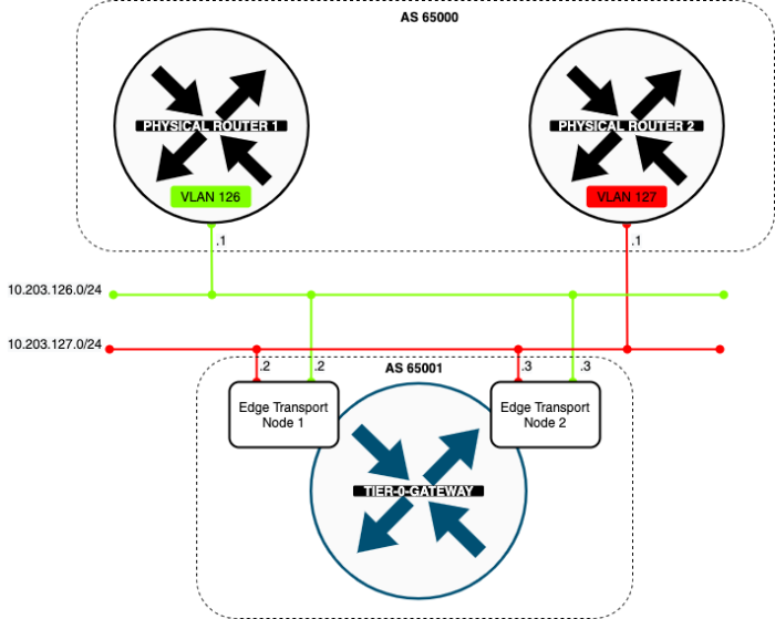
In the diagram below you see that I have one Tier-0 Gateway already configured and this Tier-0 Gateway has two uplink VLANs (VLAN 126 + 127). The Tier-0 Gateway has peers to Layer-3 BGP peers on the physical network.
My endresult
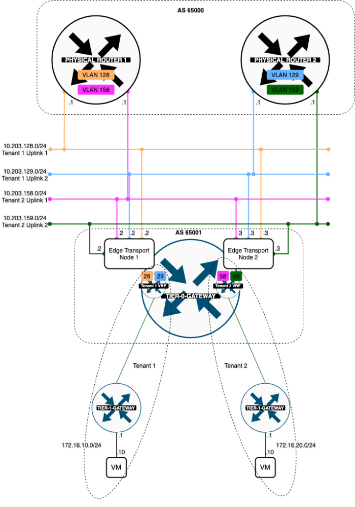
When I am finished with the VRF Lite configuration I have added two VRF enabled Tier-0 Gateway representing two separate tenants. Both tenants will each have a dedicated pair of uplink VLANs. Tenant 1 is using VLAN 128 + 129 and Tenant 2 is using VLAN 158 + 159.
The high–level steps
In this wiki, the high level following steps will be discussed:
- STEP 1: Create a Parent Tier-0 Gateway
- STEP 2: Create the VLAN Segments for the Uplink networks (for the tenants)
- STEP 3: Create the VRF enabled Tier-0 Gateways (for the tenants)
- STEP 4: Create the uplink interfaces on the VRF enabled Tier-0 Gateways (for the tenants)
- STEP 5: Configure the Vyatta Router(s) with the interface IP addresses and BGP for the Tenants
- STEP 6: Configure BGP on the VRF enabled Tier-0 Gateways (for the tenants)
- STEP 7: Create Tier-1 Gateways and attach these to the VRF enabled Gateways
- STEP 8: Create Test (Overlay) Segments for each tenant
- STEP 9: Enable Route Adverting and Route Redistribution
- STEP 10: Create test Virtual Machines per Tenant to perform some ping tests
- STEP 11: Perform some verification steps using CLI on the Edge Transport Nodes
- STEP 12: Perform some verification steps using Traceflow on the NSX-T GUI
- STEP 13: Perform some verification steps using the Network Topology Map on the NSX-T GUI
- STEP 14: Configure Route leaking between the two tenants (Inter-VRF-Routing)
The configuration steps
STEP 1» Create a Parent Tier–0 Gateway
I already preconfigured this part and here are the screenshots with the current configuration of the initial Parent Tier-0 Gateway.
The VLAN Segments for the Uplink networks
This is the NSX-T Segment that was created for the first BGP uplink for the parent Tier-0 Gateway transporting VLAN 126.
This is the NSX-T Segment that was created for the second BGP uplink for the parent Tier-0 Gateway transporting VLAN 127.
The Tier–0 Parent Gateway
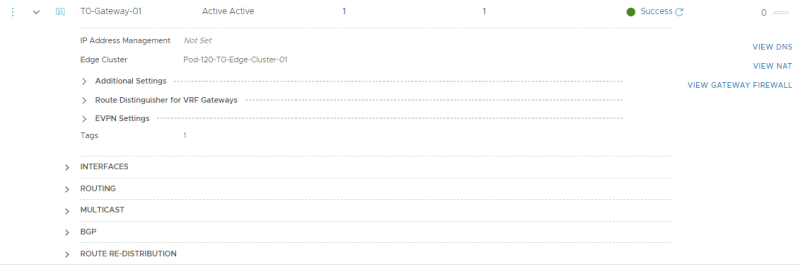
This is the parent Tier-0 Gateway that was created that will initially be the "host" for theVRF enabled Tier-0 Gateways.
The uplink interfaces for the Tier–0 Parent Gateway
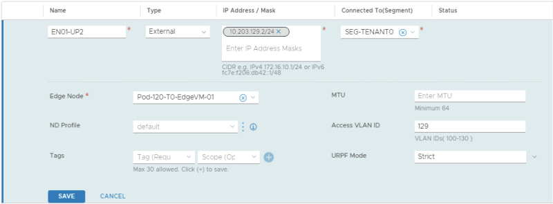
On the parent Tier-0 Gateway, I needed to configure four uplinks in total, two uplink interfaces on the first Edge Transport Node, and two uplink interfaces on the second Edge Transport Node.
These are the uplink interfaces that are configured for the first Edge Transport Node.
These are the uplink interfaces that are configured for the second Edge Transport Node.
The BGP configuration for the Tier–0 Parent Gateway
This is the BGP configuration on the parent Tier-0 Gateway.
This is the configuration for the first BGP peer that travels across VLAN 126.
This is the configuration for the second BGP peer that travels across VLAN 127.
The BGP configuration on the Vyatta Gateway〈s〉
I have used a virtual Vyatta Router that I have configured peering to. The configuration for the interfaces and BGP on the "physical" side is below.
set interfaces ethernet eth1 vif 126 address '10.203.126.1/24'
set interfaces ethernet eth1 vif 126 description 'NSX Edge Uplink #1'
set interfaces ethernet eth1 vif 126 mtu '1500'

set interfaces ethernet eth1 vif 127 address '10.203.127.1/24'
set interfaces ethernet eth1 vif 127 description 'NSX Edge Uplink #2'
set interfaces ethernet eth1 vif 127 mtu '1500'

set protocols bgp 65000 neighbor 10.203.126.2 address-family ipv4-unicast default-originate
set protocols bgp 65000 neighbor 10.203.126.2 description 'Pod-120-T0-EdgeVM-01-1'
set protocols bgp 65000 neighbor 10.203.126.2 remote-as '65001'
set protocols bgp 65000 neighbor 10.203.126.3 address-family ipv4-unicast default-originate
set protocols bgp 65000 neighbor 10.203.126.3 description 'Pod-120-T0-EdgeVM-02-1'
set protocols bgp 65000 neighbor 10.203.126.3 remote-as '65001'

set protocols bgp 65000 neighbor 10.203.127.2 address-family ipv4-unicast default-originate
set protocols bgp 65000 neighbor 10.203.127.2 description 'Pod-120-T0-EdgeVM-01-2'
set protocols bgp 65000 neighbor 10.203.127.2 remote-as '65001'
set protocols bgp 65000 neighbor 10.203.127.3 address-family ipv4-unicast default-originate
set protocols bgp 65000 neighbor 10.203.127.3 description 'Pod-120-T0-EdgeVM-02-2'
set protocols bgp 65000 neighbor 10.203.127.3 remote-as '65001'
STEP 2» Create the VLAN Segments for the Uplink networks 〈for the tenants〉
For the VRF enabled Tier-0 Gateways I need to create dedicated uplink interfaces.
TENANT 1
For tenant 1 I am going to create a trunk interface that allows multiple VLANs through the trunk. VLAN 128 + 129 needs to be in this range as these VLANS are used for the BGP uplink for the first tenant VRF enabled Tier-0 Gateway.
| Segment Name | VLAN Range | Uplink Teaming Policy | Transport Zone |
|---|---|---|---|
| SEG-TENANT01-UP1 | 100-130 | none | TZ-Edge |
| SEG-TENANT01-UP2 | 100-130 | none | TZ-Edge |
This is the creation of the first (trunked) uplink for the first tenant.
This is the creation of the second (trunked) uplink for the first tenant.
TENANT 2
For tenant 2 I am going to create a trunk interface that allows multiple VLANs through the trunk. VLAN 158 + 159 needs to be in this range as these VLANS are used for the BGP uplink for the second tenant VRF enabled Tier-0 Gateway.
| Segment Name | VLAN Range | Uplink Teaming Policy | Transport Zone |
|---|---|---|---|
| SEG-TENANT02-UP1 | 131-160 | none | TZ-Edge |
| SEG-TENANT02-UP2 | 131-160 | none | TZ-Edge |
This is the creation of the first (trunked) uplink for the second tenant.
This is the creation of the second (trunked) uplink for the second tenant.
STEP 3» Create the VRF enabled Tier–0 Gateways 〈for the tenants〉
I now need to create the actual VRF enabled Tier-0 Gateways for both tenants.
TENANT 1
Here I create the VRF enabled Tier-0 Gateway for the first tenant.
TENANT 2
Here I create the VRF enabled Tier-0 Gateway for the second tenant.
Tier–0 Gateway Overview
This is an overview of all the (VRF enabled) Tier-0 Gateways.
STEP 4» Create the uplink interfaces on the VRF enabled Tier–0 Gateways 〈for the tenants〉
Now that the VRF enabled Tier-0 Gateways are present I am going to configure the uplinks on both VRF enabled Tier-0 Gateways.
TENANT 1
In the table below I have captured the configuration parameters used for the configuration.
| VRF Name | Interface Name | IP address | Segment Name | VLAN-ID |
|---|---|---|---|---|
| TENANT01 | EN01-UP1 | 10.203.128.2/24 | SEG-TENANT01-UP1 | 128 |
| TENANT01 | EN01-UP2 | 10.203.129.2/24 | SEG-TENANT01-UP2 | 129 |
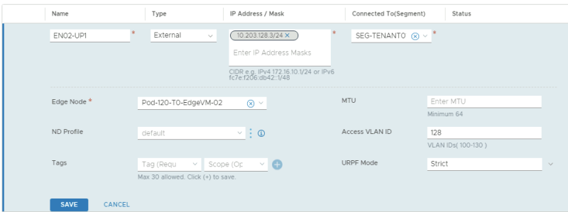
| TENANT01 | EN02-UP1 | 10.203.128.3/24 | SEG-TENANT01-UP1 | 128 |
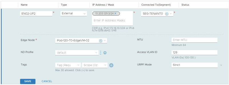
| TENANT01 | EN02-UP2 | 10.203.129.3/24 | SEG-TENANT01-UP2 | 129 |
This is the configuration for the first uplink dedicated to the first Edge Transport Node.
This is the configuration for the second uplink dedicated to the first Edge Transport Node.
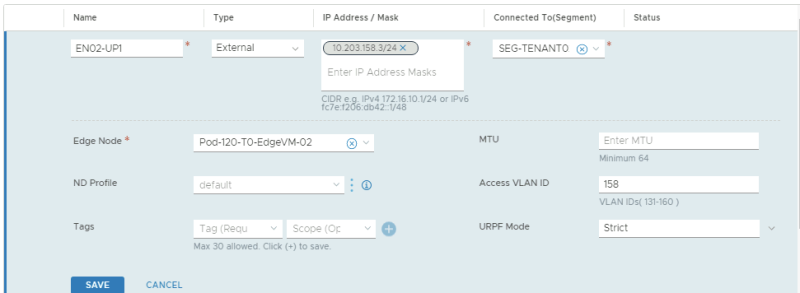
This is the configuration for the first uplink dedicated to the second Edge Transport Node.
This is the configuration for the second uplink dedicated to the second Edge Transport Node.
This is an overview of all the uplink interfaces that are configured for both Edge Transport Nodes.
TENANT 2
In the table below I have captured the configuration parameters used for the configuration.
| VRF Name | Interface Name | IP address | Segment Name | VLAN-ID |
|---|---|---|---|---|
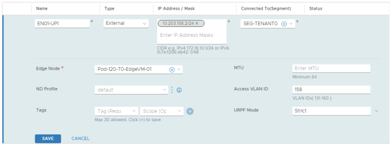
| TENANT02 | EN01-UP1 | 10.203.158.2/24 | SEG-TENANT02-UP1 | 158 |
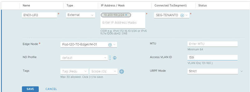
| TENANT02 | EN01-UP2 | 10.203.159.2/24 | SEG-TENANT02-UP2 | 159 |
| TENANT02 | EN02-UP1 | 10.203.158.3/24 | SEG-TENANT02-UP1 | 158 |
| TENANT02 | EN02-UP2 | 10.203.159.3/24 | SEG-TENANT02-UP2 | 159 |
This is the configuration for the first uplink dedicated to the first Edge Transport Node.
This is the configuration for the second uplink dedicated to the first Edge Transport Node.
This is the configuration for the first uplink dedicated to the second Edge Transport Node.
This is the configuration for the second uplink dedicated to the second Edge Transport Node.
This is an overview of all the uplink interfaces that are configured for both Edge Transport Nodes.
STEP 5» Configure the Vyatta Router〈s〉 with the interface IP addresses and BGP for the Tenants
I have used a virtual Vyatta Router that I have configured peering to. The configuration for the interfaces and BGP on the "VRF" sides is below.
configure

set interfaces ethernet eth1 vif 128 address '10.203.128.1/24'
set interfaces ethernet eth1 vif 128 description 'BGP Uplink 1 Tenant 1'
set interfaces ethernet eth1 vif 128 mtu '1500'
set interfaces ethernet eth1 vif 129 address '10.203.129.1/24'
set interfaces ethernet eth1 vif 129 description 'BGP Uplink 2 Tenant 1'
set interfaces ethernet eth1 vif 129 mtu '1500'
set interfaces ethernet eth1 vif 158 address '10.203.158.1/24'
set interfaces ethernet eth1 vif 158 description 'BGP Uplink 1 Tenant 2'
set interfaces ethernet eth1 vif 158 mtu '1500'
set interfaces ethernet eth1 vif 159 address '10.203.159.1/24'
set interfaces ethernet eth1 vif 159 description 'BGP Uplink 2 Tenant 2'
set interfaces ethernet eth1 vif 159 mtu '1500'

set protocols bgp 65000 neighbor 10.203.128.2 address-family ipv4-unicast default-originate
set protocols bgp 65000 neighbor 10.203.128.2 description 'TEN1-T0-EdgeVM-01-1'
set protocols bgp 65000 neighbor 10.203.128.2 remote-as '65001'
set protocols bgp 65000 neighbor 10.203.128.3 address-family ipv4-unicast default-originate
set protocols bgp 65000 neighbor 10.203.128.3 description 'TEN1-T0-EdgeVM-02-1'
set protocols bgp 65000 neighbor 10.203.128.3 remote-as '65001'
set protocols bgp 65000 neighbor 10.203.129.2 address-family ipv4-unicast default-originate
set protocols bgp 65000 neighbor 10.203.129.2 description 'TEN1-T0-EdgeVM-01-2'
set protocols bgp 65000 neighbor 10.203.129.2 remote-as '65001'
set protocols bgp 65000 neighbor 10.203.129.3 address-family ipv4-unicast default-originate
set protocols bgp 65000 neighbor 10.203.129.3 description 'TEN1-T0-EdgeVM-02-2'
set protocols bgp 65000 neighbor 10.203.129.3 remote-as '65001'
set protocols bgp 65000 neighbor 10.203.158.2 address-family ipv4-unicast default-originate
set protocols bgp 65000 neighbor 10.203.158.2 description 'TEN2-T0-EdgeVM-01-1'
set protocols bgp 65000 neighbor 10.203.158.2 remote-as '65001'
set protocols bgp 65000 neighbor 10.203.158.3 address-family ipv4-unicast default-originate
set protocols bgp 65000 neighbor 10.203.158.3 description 'TEN2-T0-EdgeVM-02-1'
set protocols bgp 65000 neighbor 10.203.158.3 remote-as '65001'
set protocols bgp 65000 neighbor 10.203.159.2 address-family ipv4-unicast default-originate
set protocols bgp 65000 neighbor 10.203.159.2 description 'TEN2-T0-EdgeVM-01-2'
set protocols bgp 65000 neighbor 10.203.159.2 remote-as '65001'
set protocols bgp 65000 neighbor 10.203.159.3 address-family ipv4-unicast default-originate
set protocols bgp 65000 neighbor 10.203.159.3 description 'TEN2-T0-EdgeVM-02-2'
set protocols bgp 65000 neighbor 10.203.159.3 remote-as '65001'

commit
save
STEP 6» Configure BGP on the VRF enabled Tier–0 Gateways 〈for the tenants〉
Now I am going configure BGP on the VRF enabled Tier-0 Gateways.
TENANT 1
| BGP Neighbor IP address | BGP Remote AS |
|---|---|
| 10.203.128.1 | 65000 |
| 10.203.129.1 | 65000 |
By default (in the NSX-t version I am using for this article = 3.0.1.1) BGP is disabled on the VRF enabled Tier-0 Gateway.
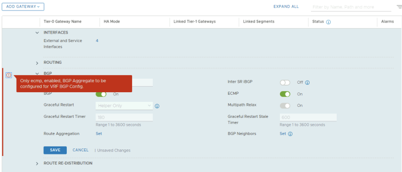
When I try to enable is I am getting the following error message. This message is unfortunately related to a bug.
In NSX-T version 3.0.1 and 3.0.1.1 you may run into the following message when you try to enable BGP on a VRF enabled Tier-0 Gateway:
"Only ECMP, enabled, BGP Aggregrate to be configured for VRF BGP Config."
This is related to a bug where you can not enable BGP (by default it's off) on a VRF enabled Tier-0 Gateway. The workaround is shown below.
The workaround for this bug is described below.
Before I used the workaround to enable BGP on the VRF enabled Tier-0 Gateway I decided to first configure the BGP peers.
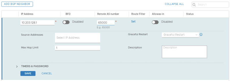
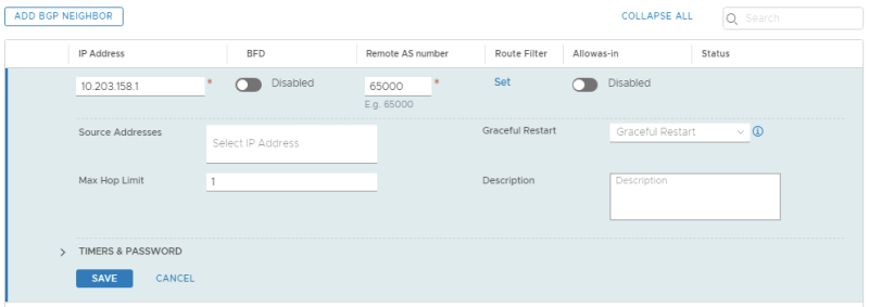
This is the BGP configuration for the first BGP peer for the first Tenant using VLAN 128.
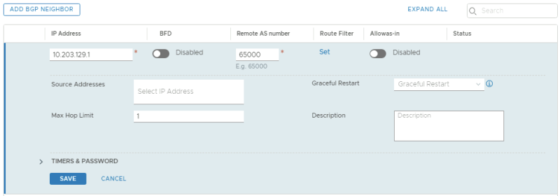
This is the BGP configuration for the second BGP peer for the first Tenant using VLAN 129.
This is a summary of the BGP peering configuration. Notice they are all down and this has to do with the fact that BGP on the first VRF enabled Tier-0 Gateway is not enabled.
Workaround for BGP bug
When you are hitting this bug when you are enabling BGP on a VRF enabled Tier-0 Gateway with the message:
"Only ECMP, enabled, BGP Aggregrate to be configured for VRF BGP Config."
And BGP can not be enabled through the NSX-T GUI you need to enable BGP using the REST API.
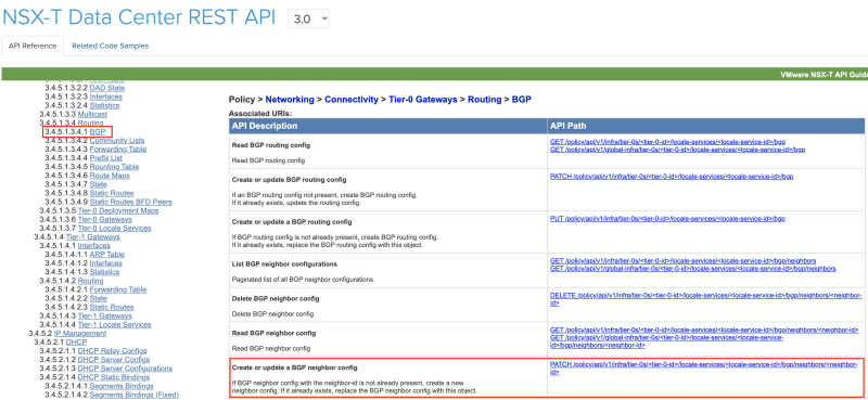
The Rest API call for this can be found in the NSX-T 3.0.0 API Guide.
The API URI to enable BGP is:
PATCH
https://pod-120-nsxt-lm.sddc.lab/policy/api/v1/infra/tier-0s/<tier-0-id>/locale-services/<locale-service-id>/bgp/
But before we can execute this REST API call I first need to know the <tier-0-id> and the <locale-service-id>.
To find out the <tier-0-id> I used the following API call:
'GET
https://pod-120-nsxt-lm.sddc.lab/policy/api/v1/infra/tier-0s
This resulted in the following output:
CLICK ON EXPAND ===> ON THE RIGHT ===> TO SEE THE OUTPUT ===> :
{
  "results": [
    {
      "transit_subnets": [
        "100.64.0.0/16"
      ],
      "internal_transit_subnets": [
        "169.254.0.0/24"
      ],
      "ha_mode": "ACTIVE_ACTIVE",
      "failover_mode": "NON_PREEMPTIVE",
      "ipv6_profile_paths": [
        "/infra/ipv6-ndra-profiles/default",
        "/infra/ipv6-dad-profiles/default"
      ],
      "force_whitelisting": false,
      "default_rule_logging": false,
      "disable_firewall": false,
      "resource_type": "Tier0",
      "id": "T0-Gateway-01",
      "display_name": "T0-Gateway-01",
      "tags": [
        {
          "scope": "SDDC.Lab",
          "tag": "Auto-Created"
        }
      ],
      "path": "/infra/tier-0s/T0-Gateway-01",
      "relative_path": "T0-Gateway-01",
      "parent_path": "/infra",
      "unique_id": "675e9483-045e-4908-94eb-5f4474388c06",
      "marked_for_delete": false,
      "overridden": false,
      "_create_user": "admin",
      "_create_time": 1597959370007,
      "_last_modified_user": "admin",
      "_last_modified_time": 1597959370074,
      "_system_owned": false,
      "_protection": "NOT_PROTECTED",
      "_revision": 0
    },
    {
      "transit_subnets": [
        "100.64.0.0/16"
      ],
      "internal_transit_subnets": [
        "169.254.0.0/24"
      ],
      "ha_mode": "ACTIVE_ACTIVE",
      "failover_mode": "NON_PREEMPTIVE",
      "ipv6_profile_paths": [
        "/infra/ipv6-ndra-profiles/default",
        "/infra/ipv6-dad-profiles/default"
      ],
      "force_whitelisting": false,
      "default_rule_logging": false,
      "disable_firewall": false,
      "vrf_config": {
        "tier0_path": "/infra/tier-0s/T0-Gateway-01",
        "marked_for_delete": false,
        "overridden": false,
        "_protection": "NOT_PROTECTED"
      },
      "resource_type": "Tier0",
      "id": "TENANT01",
      "display_name": "TENANT01",
      "path": "/infra/tier-0s/TENANT01",
      "relative_path": "TENANT01",
      "parent_path": "/infra",
      "unique_id": "70435935-f34e-44d6-919c-d36e06b62109",
      "marked_for_delete": false,
      "overridden": false,
      "_create_user": "admin",
      "_create_time": 1598038169130,
      "_last_modified_user": "admin",
      "_last_modified_time": 1598038169203,
      "_system_owned": false,
      "_protection": "NOT_PROTECTED",
      "_revision": 0
    },
    {
      "transit_subnets": [
        "100.64.0.0/16"
      ],
      "internal_transit_subnets": [
        "169.254.0.0/24"
      ],
      "ha_mode": "ACTIVE_ACTIVE",
      "failover_mode": "NON_PREEMPTIVE",
      "ipv6_profile_paths": [
        "/infra/ipv6-ndra-profiles/default",
        "/infra/ipv6-dad-profiles/default"
      ],
      "force_whitelisting": false,
      "default_rule_logging": false,
      "disable_firewall": false,
      "vrf_config": {
        "tier0_path": "/infra/tier-0s/T0-Gateway-01",
        "marked_for_delete": false,
        "overridden": false,
        "_protection": "NOT_PROTECTED"
      },
      "resource_type": "Tier0",
      "id": "TENANT02",
      "display_name": "TENANT02",
      "path": "/infra/tier-0s/TENANT02",
      "relative_path": "TENANT02",
      "parent_path": "/infra",
      "unique_id": "a5486158-6ba0-4a79-bed6-777220fdab9d",
      "marked_for_delete": false,
      "overridden": false,
      "_create_user": "admin",
      "_create_time": 1598038266592,
      "_last_modified_user": "admin",
      "_last_modified_time": 1598038266650,
      "_system_owned": false,
      "_protection": "NOT_PROTECTED",
      "_revision": 0
    }
  ],
  "result_count": 3,
  "sort_by": "display_name",
  "sort_ascending": true
}
This tells me that the <tier-0-id> is "TENANT01" and/or "TENANT02".
To find out the <locale-service-id> I used the following API call:
'GET
https://pod-120-nsxt-lm.sddc.lab/policy/api/v1/infra/tier-0s/TENANT01/locale-services
This resulted in the following output:
CLICK ON EXPAND ===> ON THE RIGHT ===> TO SEE THE OUTPUT ===> :
{
  "results": [
    {
      "edge_cluster_path": "/infra/sites/default/enforcement-points/default/edge-clusters/11826748-46da-45a4-9abf-eb53ee87042b",
      "resource_type": "LocaleServices",
      "id": "default",
      "display_name": "default",
      "path": "/infra/tier-0s/TENANT01/locale-services/default",
      "relative_path": "default",
      "parent_path": "/infra/tier-0s/TENANT01",
      "unique_id": "6ffc2d5c-defd-46a8-aad6-352e1d86c6b9",
      "marked_for_delete": false,
      "overridden": false,
      "_create_user": "admin",
      "_create_time": 1598038169523,
      "_last_modified_user": "admin",
      "_last_modified_time": 1598038169527,
      "_system_owned": false,
      "_protection": "NOT_PROTECTED",
      "_revision": 0
    }
  ],
  "result_count": 1,
  "sort_by": "display_name",
  "sort_ascending": true
}
This tells me that the <locale-service-id> is "default".
So I first performed a "GET" to find out what the JSON syntax and status of the BGP protocol was using the following API call:
'GET
https://pod-120-nsxt-lm.sddc.lab/policy/api/v1/infra/tier-0s/TENANT01/locale-services/default/bgp
This resulted in the following output:
CLICK ON EXPAND ===> ON THE RIGHT ===> TO SEE THE OUTPUT ===> :
{
  "enabled": false,
  "ecmp": true,
  "resource_type": "BgpRoutingConfig",
  "id": "bgp",
  "display_name": "bgp",
  "path": "/infra/tier-0s/TENANT01/locale-services/default/bgp",
  "relative_path": "bgp",
  "parent_path": "/infra/tier-0s/TENANT01/locale-services/default",
  "unique_id": "c14d888b-951c-4ed2-8a6e-36d5bd185cd7",
  "marked_for_delete": false,
  "overridden": false,
  "_create_user": "admin",
  "_create_time": 1598038169569,
  "_last_modified_user": "admin",
  "_last_modified_time": 1598038169574,
  "_system_owned": false,
  "_protection": "NOT_PROTECTED",
  "_revision": 0
}
Then I changed the following:
"enabled": false,
to
"enabled": true,
And I executed the following API call:
PATCH
https://pod-120-nsxt-lm.sddc.lab/policy/api/v1/infra/tier-0s/TENANT01/locale-services/default/bgp
using the following JSON code:
CLICK ON EXPAND ===> ON THE RIGHT ===> TO SEE THE OUTPUT ===> :
{
  "enabled": true,
  "ecmp": true,
  "resource_type": "BgpRoutingConfig",
  "id": "bgp",
  "display_name": "bgp",
  "path": "/infra/tier-0s/TENANT01/locale-services/default/bgp",
  "relative_path": "bgp",
  "parent_path": "/infra/tier-0s/TENANT01/locale-services/default",
  "unique_id": "c14d888b-951c-4ed2-8a6e-36d5bd185cd7",
  "marked_for_delete": false,
  "overridden": false,
  "_create_user": "admin",
  "_create_time": 1598038169569,
  "_last_modified_user": "admin",
  "_last_modified_time": 1598038169574,
  "_system_owned": false,
  "_protection": "NOT_PROTECTED",
  "_revision": 0
}
And once executed I received a Status: 200 OK:
Now when I take a look in the GUI I see that the BGP switch is now turned on:
And my BGP peers that were down before because BGP could not be enabled are now up:
UPDATE: on 28 OCT 2020 I have tested this again with NSX-T version 3.0.2 and I was able to create a VRF without any issue.
TENANT 2
| BGP Neighbor IP address | BGP Remote AS |
|---|---|
| 10.203.158.1 | 65000 |
| 10.203.159.1 | 65000 |
By default, BGP is disabled (for TENANT02) on the VRF Enabled Tier-0 Gateway like you have seen with the configuration of the VRF Enabled Tier-0 Gateway for TENANT01 above.
I hit the same bug again.
After I used the workaround I have described above BGP was enabled successfully.
This is the BGP configuration for the first BGP peer for the second Tenant using VLAN 158.
This is the BGP configuration for the second BGP peer for the second Tenant using VLAN 159.
This is a summary of the BGP peering configuration. Notice they are all up and this has to do with the fact that BGP was enabled on the second VRF enabled Tier-0 Gateway by using the workaround before I configured the BGP peers.
STEP 7» Create Tier–1 Gateways and attach these to the VRF enabled Gateways
Here I am creating dedicated Tier-1 Gateways that I will attach to the VRF enabled Tier-0 Gateways.
TENANT 1
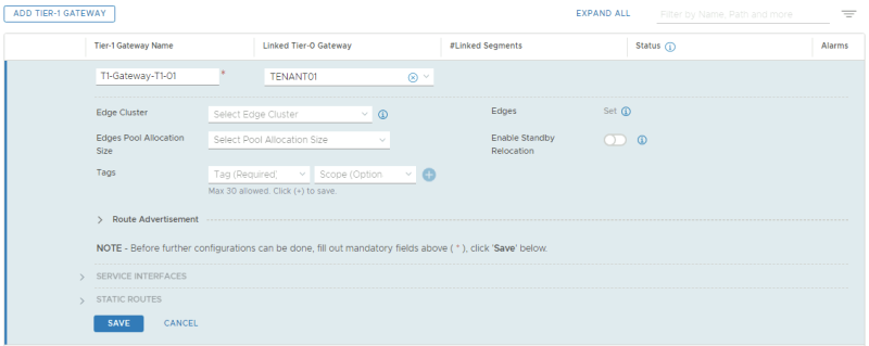
This is the dedicated Tier-1 Gateway for the first tenant.
TENANT 2
This is the dedicated Tier-1 Gateway for the second tenant.
Tier–1 Gateway Summary
This is a summary of all the Tier-1 Gateways.
STEP 8» Create Test 〈Overlay〉 Segments for each tenant
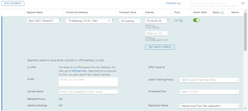
I have created two additional overlay segments that are going to be attached to the Tier-1 Gateways so I can attach two VMs to these segments to simulate end-to-end networking.
TENANT 1
In the table below I have captured the configuration parameters used for the configuration.
| Segment Name | Connected Gateway | Transport Zone | IP Address |
|---|---|---|---|
| SEG-TEST-TENANT01 | T1-Gateway-T1-01 | TZ-Overlay - Overlay | 172.16.10.1/24 |
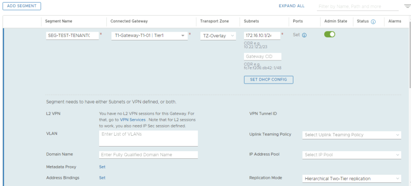
Here I create the test overlay segment for the first tenant.
TENANT 2
In the table below I have captured the configuration parameters used for the configuration.
| Segment Name | Connected Gateway | Transport Zone | IP Address |
|---|---|---|---|
| SEG-TEST-TENANT02 | T1-Gateway-T1-02 | TZ-Overlay - Overlay | 172.16.20.1/24 |
Here I create the test overlay segment for the second tenant.
STEP 9» Enable Route Adverting and Route Redistribution
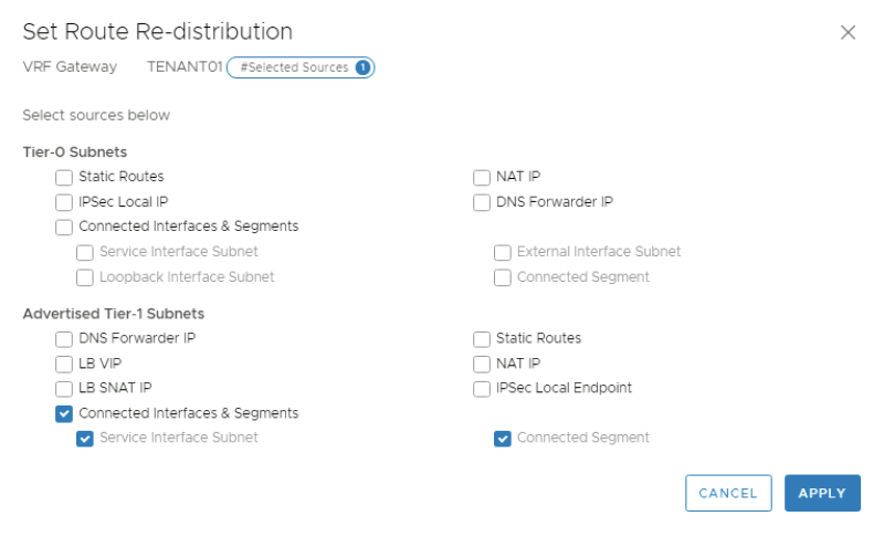
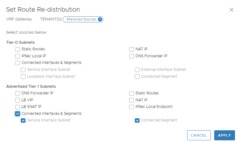
To make sure the physical network will receive the routes of the specific tenants I need to enable route advertising for the connected networks on the Tier-1 Gateways, and I need to configure route redistribution on the VRF enabled Tier-0 Gateway so make sure that the routes that are learned from the Tier-1 Gateway are (re)advertised to the physical network.
TENANT 1
Route Advertisement on Tier–1 Gateway
First I enabled route advertisement on the Tier-1 Gateway for the connected segments.
Route Redistribution on VRF enabled Tier–0 Gateway
First I need to go to the route re-distribution section of the VRF enabled Tier-0 Gateway.
Provide a name for the route re-distribution entry and click on "set".
Select the"Connected Interfaces & Segments" checkbox in the "Advertised Tier-1 Subnets" section.
Click on Apply and look for the "1" to see if the "Route Re-distribution" entry is added. Click "Add".
Click on "Save"
TENANT 2
Route Advertisement on Tier–1 Gateway
First I enabled route advertisement on the Tier-1 Gateway for the connected segments.
Route Redistribution on VRF enabled Tier–0 Gateway
First I need to go to the route re-distribution section of the VRF enabled Tier-0 Gateway.
Provide a name for the route re-distribution entry and click on "set".
Select the"Connected Interfaces & Segments" checkbox in the "Advertised Tier-1 Subnets" section.
Click on Apply and look for the "1" to see if the "Route Re-distribution" entry is added. Click "Add".
Click on "Save"
STEP 10» Create test Virtual Machines per Tenant to perform some ping tests
For my test Virtual Machines, I am using PHOTON OS Virtual Machines that you can download here.
For this test I downloaded the following file: photon-hw13_uefi-3.0-074f0525.ova
TENANT 1
Creating Test VM using Photon OS
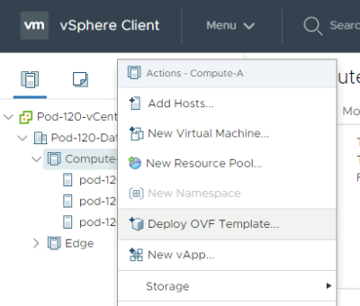
Deploy a new OVF Template from the Center Server Client.
Select the local Photon OS ova file.
Provide a name for your Virtual Machine.
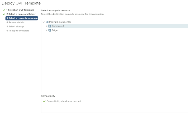
Select a computing resource where you want to deploy the VM to.
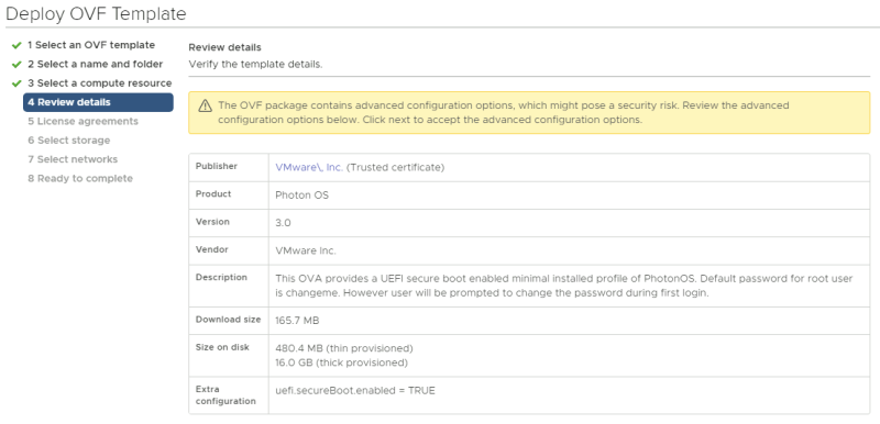
Review the details and just click next.
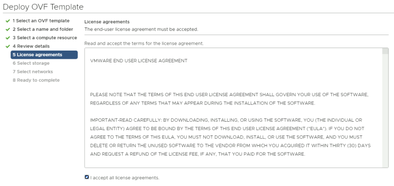
Accept the license agreement.
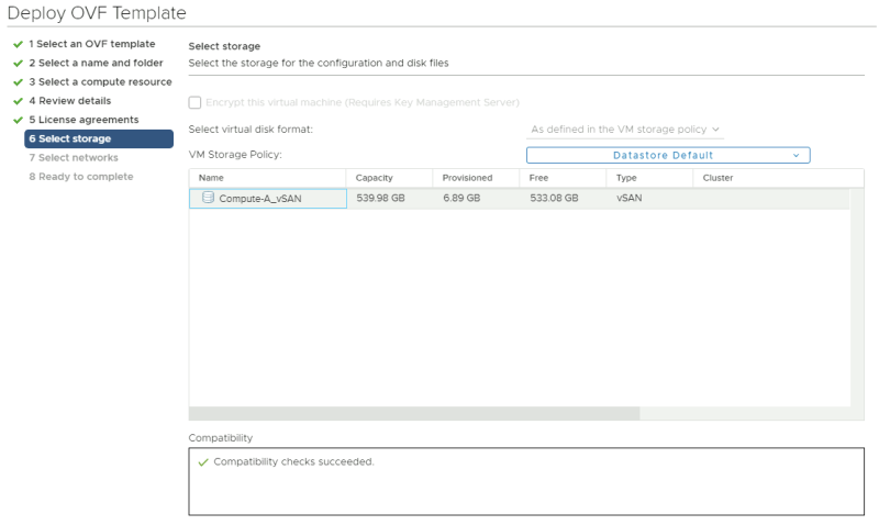
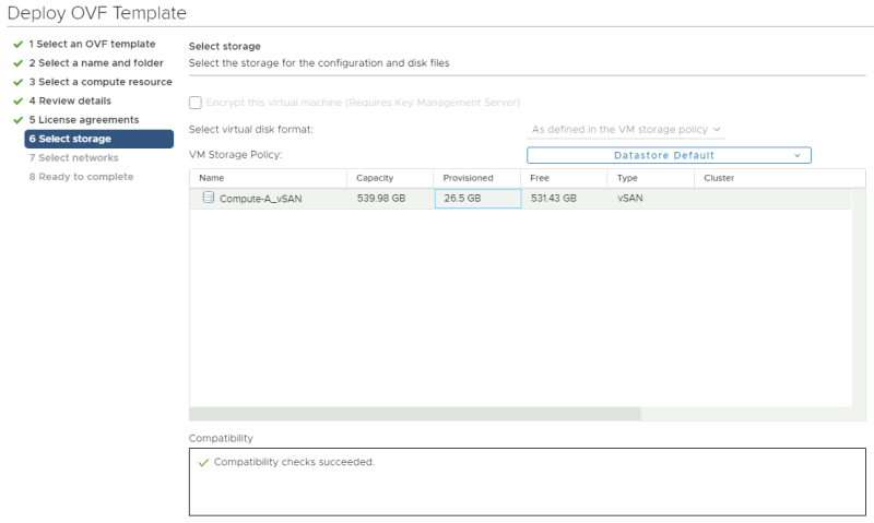
Select a storage resource where you want to deploy the VM to.
Select a networking resource that you want you're VM to be attached to. Make sure you select the Test Overlay Tenant 1 Segment you created.
Review the details before you finish.
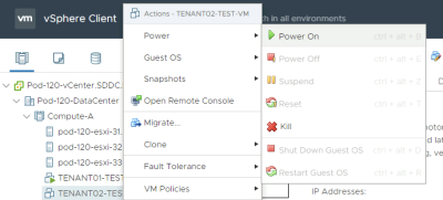
Power on the new Virtual Machine.
Network Configuration and Ping Tests
When the VM is ready and power on we need to log in to the console and provide network settings. the first time you log in to a newly deployed Photon OS VM you need to change the password. The default username is "root" and the default password is "changeme".
Welcome to Photon 3.0 (x86_64) - Kernel 4.19.79-1.ph3-esx (tty1)
photon-machine login: root
Password: changeme
You are required to change your password immediately (administrator enforced)
Changing password for root.
Current password: changeme
New password: VMware1!VMware1!
Retype new password: VMware1!VMware1!
Here we change the hostname.
root@photon-machine [ ~ ]# hostnamectl set-hostname tenant01-test-vm
Here we create a network interface configuration file to specify the static IP address details for the network interface.
root@photon-machine [ ~ ]# vi /etc/systemd/network/10-static-en.network
This is the content of the "10-static-en.network" file.
[Match]
Name=eth0

[Network]
Address=172.16.10.11/24
Gateway=172.16.10.1
Here we change the rights to the file so the system is allowed to use it.
root@photon-machine [ ~ ]# chmod 644 /etc/systemd/network/10-static-en.network
Here we restart the networking service of the VM.
root@photon-machine [ ~ ]# systemctl restart systemd-networkd
Here we reboot the machine.
root@photon-machine [ ~ ]# reboot
When the machine is rebooted (with the new hostname) we can verify if the IP address is correct.
root@tenant01-test-vm [ ~ ]# ip a
Here I do a quick ping towards my gateway to verify if we have network connectivity.
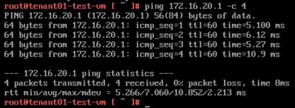
Here I do a ping to the other tenant UPLINK interface (172.16.20.1).
TENANT 2
Creating Test VM using Photon OS
Deploy a new OVF Template from the Center Server CLient.
Select the local Photon OS ova file. Provide a name for your Virtual Machine (screenshot not provided).
Select a computing resource where you want to deploy the VM to.
Review the details and just click next.
Accept the license agreement.
Select a storage resource where you want to deploy the VM to.
Select a networking resource that you want you're VM to be attached to. Make sure you select the Test Overlay Tenant 2 Segment you created.
Review the details before you finish.
Power on the new Virtual Machine.
Network Configuration and Ping Tests
When the VM is ready and power on we need to log in to the console and provide network settings. the first time you log in to a newly deployed Photon OS VM you need to change the password. The default username is "root" and the default password is "changeme".
Welcome to Photon 3.0 (x86_64) - Kernel 4.19.79-1.ph3-esx (tty1)
photon-machine login: root
Password: changeme
You are required to change your password immediately (administrator enforced)
Changing password for root.
Current password: changeme
New password: VMware1!VMware1!
Retype new password: VMware1!VMware1!
Here we change the hostname.
root@photon-machine [ ~ ]# hostnamectl set-hostname tenant02-test-vm
Here we create a network interface configuration file to specify the static IP address details for the network interface.
root@photon-machine [ ~ ]# vi /etc/systemd/network/10-static-en.network
This is the content of the "10-static-en.network" file.
[Match]
Name=eth0

[Network]
Address=172.16.20.11/24
Gateway=172.16.20.1
Here we change the rights to the file so the system is allowed to use it.
root@photon-machine [ ~ ]# chmod 644 /etc/systemd/network/10-static-en.network
Here we restart the networking service of the VM.
root@photon-machine [ ~ ]# systemctl restart systemd-networkd
Here we reboot the machine.
root@photon-machine [ ~ ]# reboot
When the machine is rebooted (with the new hostname) we can verify if the IP address is correct.
root@tenant02-test-vm [ ~ ]# ip a
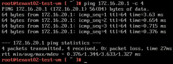
Here I do a quick ping towards my gateway to verify if we have network connectivity.
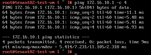
Here I do a ping to the other tenant UPLINK interface (172.16.10.1).
STEP 11» Perform some verification steps using CLI on the Edge Transport Nodes
Pod–120–T0–EdgeVM–01 〈Edge Transport Node 1〉
Here we verify what SR and DR components are created. You see that the "SR-VRF-TENANT01" and the "SR-VRF-TENANT02" Logical Routers are created that will take care of the BGP uplink configuration.
Pod-120-T0-EdgeVM-01> get logical-routers
Logical Router
UUID                                   VRF    LR-ID  Name                              Type                        Ports
736a80e3-23f6-5a2d-81d6-bbefb2786666   0      0                                        TUNNEL                      4
b3c546e7-ff12-4cc4-987a-cf657a93234e   1      4      SR-T0-Gateway-01                  SERVICE_ROUTER_TIER0        11
9825b3b1-490b-4b5d-8e7d-d270c03fd3a4   3      3      DR-T1-Gateway-01                  DISTRIBUTED_ROUTER_TIER1    7
675e9483-045e-4908-94eb-5f4474388c06   4      1      DR-T0-Gateway-01                  DISTRIBUTED_ROUTER_TIER0    5
f16a09eb-3c3a-422e-ab6f-cf0514b0b165   5      11     SR-VRF-TENANT01                   VRF_SERVICE_ROUTER_TIER0    6
627d6ef3-b679-4886-ab85-1de74f44f2c2   6      14     SR-VRF-TENANT02                   VRF_SERVICE_ROUTER_TIER0    6
70435935-f34e-44d6-919c-d36e06b62109   7      9      DR-VRF-TENANT01                   VRF_DISTRIBUTED_ROUTER_TIER0 4
a3e29737-7abe-4f41-95cd-1fdfc65adf7a   8      19     DR-T1-Gateway-T1-01               DISTRIBUTED_ROUTER_TIER1    5
a5486158-6ba0-4a79-bed6-777220fdab9d   9      12     DR-VRF-TENANT02                   VRF_DISTRIBUTED_ROUTER_TIER0 4
3637f632-96f6-40cb-b348-af9d263d3452   10     20     DR-T1-Gateway-T2-01               DISTRIBUTED_ROUTER_TIER1    5
Let's log into the SR-VRF-TENANT01 Logical Router using VRF 5 and verify the BGP neighbor connectivity.
Pod-120-T0-EdgeVM-01> vrf 5
Pod-120-T0-EdgeVM-01(tier0_vrf_sr)> get bgp neighbor summary
BFD States: NC - Not configured, AC - Activating,DC - Disconnected
            AD - Admin down, DW - Down, IN - Init,UP - Up
BGP summary information for VRF VRF-9 for address-family: ipv4Unicast
Router ID: 10.203.127.2  Local AS: 65001

Neighbor                            AS          State Up/DownTime  BFD InMsgs  OutMsgs InPfx  OutPfx

10.203.129.1                        65000       Estab 13:19:08     NC  1390    1383    1      1
10.203.128.1                        65000       Conne never        NC  0       0       0      0
Here we look at the BGP table for this specific tenant (tenant 01).
Pod-120-T0-EdgeVM-01(tier0_vrf_sr)> get bgp ipv4
BGP IPv4 table version is 4
Local router ID is 10.203.127.2
Status flags: > - best, I - internal
Origin flags: i - IGP, e - EGP, ? - incomplete

   Network                             Next Hop                            Metric       LocPrf  Weight   Path
 > 0.0.0.0/0                           10.203.129.1                        0            100     0        65000 65001 i
 > 172.16.10.0/24                      100.64.128.3                        0            100     32768    65001 ?
Here we look at the routing table for this specific tenant (tenant 01).
Pod-120-T0-EdgeVM-01(tier0_vrf_sr)> get forwarding
Logical Router
UUID                                   VRF    LR-ID  Name                              Type
f16a09eb-3c3a-422e-ab6f-cf0514b0b165   5      11     SR-VRF-TENANT01                   VRF_SERVICE_ROUTER_TIER0
IPv4 Forwarding Table
IP Prefix          Gateway IP      Type     UUID                                   Gateway MAC
0.0.0.0/0          10.203.129.1    route    d6f962c5-95ca-44ea-aed7-4d3fca91d4d2   00:0c:29:c2:a5:93
10.203.128.0/24                    route    0c1fa480-fbea-4b77-9893-d10ff41c2a1b
10.203.128.2/32                    route    c618fe04-1df1-55e1-b290-ab7c285e2d7c
10.203.129.0/24                    route    d6f962c5-95ca-44ea-aed7-4d3fca91d4d2
10.203.129.2/32                    route    c618fe04-1df1-55e1-b290-ab7c285e2d7c
100.64.128.2/32                    route    a64d1469-a468-550c-9526-eb7102133c1a
100.64.128.2/31                    route    64e87331-c284-4d20-8a69-278f08940a6f
127.0.0.1/32                       route    a59983da-7f2d-4ce2-8a8f-6a69a0786fb9
169.254.0.0/24                     route    72768eea-7bad-445e-b257-f81d8a8970ed
169.254.0.1/32                     route    a64d1469-a468-550c-9526-eb7102133c1a
169.254.0.3/32                     route    c618fe04-1df1-55e1-b290-ab7c285e2d7c
172.16.10.0/24     100.64.128.3    route    64e87331-c284-4d20-8a69-278f08940a6f
Let's log into the SR-VRF-TENANT02 Logical Router using VRF 6 and verify the BGP neighbor connectivity.
Pod-120-T0-EdgeVM-01> vrf 6
Pod-120-T0-EdgeVM-01(tier0_vrf_sr)> get bgp neighbor summary
BFD States: NC - Not configured, AC - Activating,DC - Disconnected
            AD - Admin down, DW - Down, IN - Init,UP - Up
BGP summary information for VRF VRF-12 for address-family: ipv4Unicast
Router ID: 10.203.127.2  Local AS: 65001

Neighbor                            AS          State Up/DownTime  BFD InMsgs  OutMsgs InPfx  OutPfx

10.203.159.1                        65000       Estab 12:49:00     NC  777     772     1      1
10.203.158.1                        65000       Conne never        NC  0       0       0      0
Here we look at the BGP table for this specific tenant (tenant 02).
Pod-120-T0-EdgeVM-01(tier0_vrf_sr)> get bgp ipv4
BGP IPv4 table version is 2
Local router ID is 10.203.127.2
Status flags: > - best, I - internal
Origin flags: i - IGP, e - EGP, ? - incomplete

   Network                             Next Hop                            Metric       LocPrf  Weight   Path
 > 172.16.20.0/24                      100.64.128.5                        0            100     32768    65001 ?
 > 0.0.0.0/0                           10.203.159.1                        0            100     0        65000 65001 i
Here we look at the routing table for this specific tenant (tenant 02).
Pod-120-T0-EdgeVM-01(tier0_vrf_sr)> get forwarding
Logical Router
UUID                                   VRF    LR-ID  Name                              Type
627d6ef3-b679-4886-ab85-1de74f44f2c2   6      14     SR-VRF-TENANT02                   VRF_SERVICE_ROUTER_TIER0
IPv4 Forwarding Table
IP Prefix          Gateway IP      Type     UUID                                   Gateway MAC
0.0.0.0/0          10.203.159.1    route    13cbf327-88ef-498f-b3b1-943d8f47a748   00:0c:29:c2:a5:93
10.203.158.0/24                    route    8c763a23-e65a-4672-b13f-38852108aabc
10.203.158.2/32                    route    d3f9a9c9-786e-5890-9bfa-7c478848385d
10.203.159.0/24                    route    13cbf327-88ef-498f-b3b1-943d8f47a748
10.203.159.2/32                    route    d3f9a9c9-786e-5890-9bfa-7c478848385d
100.64.128.4/32                    route    cbbdeeec-d427-58a7-9dba-a7d97b394081
127.0.0.1/32                       route    5596c144-a899-4b3d-bc68-fd442d58c91d
169.254.0.0/24                     route    6e1e1a0c-5d94-46bc-aebd-9f6c753cb4ee
169.254.0.1/32                     route    cbbdeeec-d427-58a7-9dba-a7d97b394081
169.254.0.3/32                     route    d3f9a9c9-786e-5890-9bfa-7c478848385d
172.16.20.0/24     100.64.128.5    route    95d84644-4f89-4958-bf34-6ed0857d31c8   02:50:56:56:44:55
Pod–120–T0–EdgeVM–02 〈Edge Transport Node 2〉
Here we verify what SR and DR components are created. You see that the "SR-VRF-TENANT01" and the "SR-VRF-TENANT02" Logical Routers are created that will take care of the BGP uplink configuration.
Pod-120-T0-EdgeVM-02> get logical-routers
Logical Router
UUID                                   VRF    LR-ID  Name                              Type                        Ports
736a80e3-23f6-5a2d-81d6-bbefb2786666   0      0                                        TUNNEL                      4
c9c0e9f3-65b2-440a-a583-076aa238a3e2   1      2      SR-T0-Gateway-01                  SERVICE_ROUTER_TIER0        11
9825b3b1-490b-4b5d-8e7d-d270c03fd3a4   3      3      DR-T1-Gateway-01                  DISTRIBUTED_ROUTER_TIER1    7
675e9483-045e-4908-94eb-5f4474388c06   4      1      DR-T0-Gateway-01                  DISTRIBUTED_ROUTER_TIER0    5
668e2b04-43ee-4e73-a714-0e9613b78221   5      10     SR-VRF-TENANT01                   VRF_SERVICE_ROUTER_TIER0    6
d453f169-7802-4cc7-8a08-167f4aa1ed7a   6      13     SR-VRF-TENANT02                   VRF_SERVICE_ROUTER_TIER0    6
70435935-f34e-44d6-919c-d36e06b62109   7      9      DR-VRF-TENANT01                   VRF_DISTRIBUTED_ROUTER_TIER0 4
a3e29737-7abe-4f41-95cd-1fdfc65adf7a   8      19     DR-T1-Gateway-T1-01               DISTRIBUTED_ROUTER_TIER1    5
a5486158-6ba0-4a79-bed6-777220fdab9d   9      12     DR-VRF-TENANT02                   VRF_DISTRIBUTED_ROUTER_TIER0 4
3637f632-96f6-40cb-b348-af9d263d3452   10     20     DR-T1-Gateway-T2-01               DISTRIBUTED_ROUTER_TIER1    5
Let's log into the SR-VRF-TENANT01 Logical Router using VRF 5 and verify the BGP neighbor connectivity.
Pod-120-T0-EdgeVM-02> vrf 5
Pod-120-T0-EdgeVM-02(tier0_vrf_sr)> get bgp neighbor summary
BFD States: NC - Not configured, AC - Activating,DC - Disconnected
            AD - Admin down, DW - Down, IN - Init,UP - Up
BGP summary information for VRF VRF-9 for address-family: ipv4Unicast
Router ID: 10.203.127.3  Local AS: 65001

Neighbor                            AS          State Up/DownTime  BFD InMsgs  OutMsgs InPfx  OutPfx

10.203.129.1                        65000       Conne never        NC  0       0       0      0
10.203.128.1                        65000       Estab 00:00:51     NC  1404    1394    1      1
Here we look at the BGP table for this specific tenant (tenant 01).
Pod-120-T0-EdgeVM-02(tier0_vrf_sr)> get bgp ipv4
BGP IPv4 table version is 6
Local router ID is 10.203.127.3
Status flags: > - best, I - internal
Origin flags: i - IGP, e - EGP, ? - incomplete

   Network                             Next Hop                            Metric       LocPrf  Weight   Path
 > 0.0.0.0/0                           10.203.128.1                        0            100     0        65000 65001 i
 > 172.16.10.0/24                      100.64.128.3                        0            100     32768    65001 ?
Here we look at the routing table for this specific tenant (tenant 01).
Pod-120-T0-EdgeVM-02(tier0_vrf_sr)> get forwarding
Logical Router
UUID                                   VRF    LR-ID  Name                              Type
668e2b04-43ee-4e73-a714-0e9613b78221   5      10     SR-VRF-TENANT01                   VRF_SERVICE_ROUTER_TIER0
IPv4 Forwarding Table
IP Prefix          Gateway IP      Type     UUID                                   Gateway MAC
0.0.0.0/0          10.203.128.1    route    1aa9760f-c36d-4780-87b8-75f0d7cc12a5
10.203.128.0/24                    route    1aa9760f-c36d-4780-87b8-75f0d7cc12a5
10.203.128.3/32                    route    28a45158-fe5c-545a-935a-3471c5a1889d
10.203.129.0/24                    route    0ebf292c-b6eb-45ca-b84c-5dd447d71372
10.203.129.3/32                    route    28a45158-fe5c-545a-935a-3471c5a1889d
100.64.128.2/32                    route    a64d1469-a468-550c-9526-eb7102133c1a
100.64.128.2/31                    route    64e87331-c284-4d20-8a69-278f08940a6f
127.0.0.1/32                       route    a59983da-7f2d-4ce2-8a8f-6a69a0786fb9
169.254.0.0/24                     route    5a516e3f-716b-494c-90dd-400a0047bcfc
169.254.0.1/32                     route    a64d1469-a468-550c-9526-eb7102133c1a
169.254.0.2/32                     route    28a45158-fe5c-545a-935a-3471c5a1889d
172.16.10.0/24     100.64.128.3    route    64e87331-c284-4d20-8a69-278f08940a6f   02:50:56:56:44:55
Let's log into the SR-VRF-TENANT02 Logical Router using VRF 6 and verify the BGP neighbor connectivity.
Pod-120-T0-EdgeVM-02> vrf 6
Pod-120-T0-EdgeVM-02(tier0_vrf_sr)> get bgp neighbor summary
BFD States: NC - Not configured, AC - Activating,DC - Disconnected
            AD - Admin down, DW - Down, IN - Init,UP - Up
BGP summary information for VRF VRF-12 for address-family: ipv4Unicast
Router ID: 10.203.127.3  Local AS: 65001

Neighbor                            AS          State Up/DownTime  BFD InMsgs  OutMsgs InPfx  OutPfx

10.203.159.1                        65000       Conne never        NC  0       0       0      0
10.203.158.1                        65000       Estab 00:01:39     NC  789     782     1      1
Here we look at the BGP table for this specific tenant (tenant 02).
Pod-120-T0-EdgeVM-02(tier0_vrf_sr)> get bgp ipv4
BGP IPv4 table version is 4
Local router ID is 10.203.127.3
Status flags: > - best, I - internal
Origin flags: i - IGP, e - EGP, ? - incomplete

   Network                             Next Hop                            Metric       LocPrf  Weight   Path
 > 172.16.20.0/24                      100.64.128.5                        0            100     32768    65001 ?
 > 0.0.0.0/0                           10.203.158.1                        0            100     0        65000 65001 i
Here we look at the routing table for this specific tenant (tenant 02).
Pod-120-T0-EdgeVM-02(tier0_vrf_sr)> get forwarding
Logical Router
UUID                                   VRF    LR-ID  Name                              Type
d453f169-7802-4cc7-8a08-167f4aa1ed7a   6      13     SR-VRF-TENANT02                   VRF_SERVICE_ROUTER_TIER0
IPv4 Forwarding Table
IP Prefix          Gateway IP      Type     UUID                                   Gateway MAC
0.0.0.0/0          10.203.158.1    route    5e95db40-c97d-44c9-9682-d418f4dd0305
10.203.158.0/24                    route    5e95db40-c97d-44c9-9682-d418f4dd0305
10.203.158.3/32                    route    90691403-985e-5f27-b5ac-87ef69c4260c
10.203.159.0/24                    route    87f5f8c4-594a-49e9-a1bf-e64b9f9cb134
10.203.159.3/32                    route    90691403-985e-5f27-b5ac-87ef69c4260c
100.64.128.4/32                    route    cbbdeeec-d427-58a7-9dba-a7d97b394081
100.64.128.4/31                    route    95d84644-4f89-4958-bf34-6ed0857d31c8
127.0.0.1/32                       route    5596c144-a899-4b3d-bc68-fd442d58c91d
169.254.0.0/24                     route    9c2d0144-ad65-4f1a-8fbe-acf8cb3e02ca
169.254.0.1/32                     route    cbbdeeec-d427-58a7-9dba-a7d97b394081
169.254.0.2/32                     route    90691403-985e-5f27-b5ac-87ef69c4260c
172.16.20.0/24     100.64.128.5    route    95d84644-4f89-4958-bf34-6ed0857d31c8   02:50:56:56:44:55
STEP 12» Perform some verification steps using Traceflow on the NSX–T GUI
To test connectivity between the tenant VM's we can also use NSX-T traceflow for this.
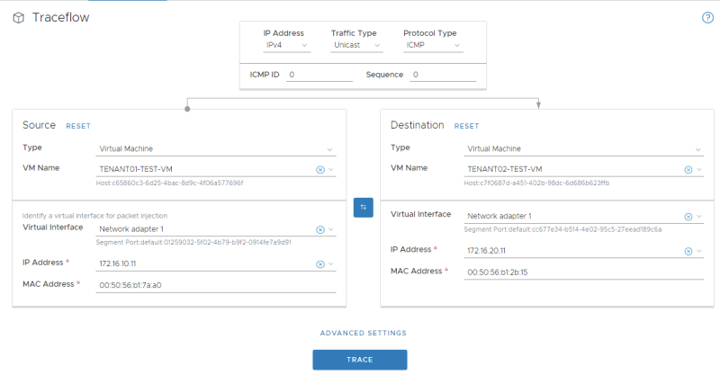
Traceflow from TENANT01–TEST–VM to TENANT02–TEST–VM
Here I have selected the virtual machine source and destination where TENANT01 is the source and TENANT02 is the destination.
Here you see the result of the traceflow. You see that NSX-T plots the network diagram of the full end-to-end connection for you.
The strange thing here is that I could not ping, but the traceflow tells me that the packet is received at the destination. I need to find out why this is.
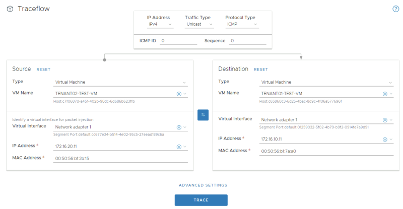
Traceflow from TENANT02–TEST–VM to TENANT01–TEST–VM
Here I have selected the virtual machine source and destination where TENANT02 is the source and TENANT01 is the destination.
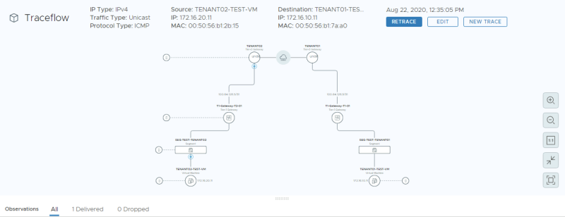
Here you see the result of the traceflow. You see that NSX-T plots the network diagram of the full end-to-end connection for you.
The strange thing here is that I could not ping, but the traceflow tells me that the packet is received at the destination. I need to find out why this is.
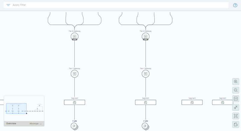
STEP 13» Perform some verification steps using the Network Topology Map on the NSX–T GUI
STEP 14» Configure Route leaking between the two tenants 〈Inter–VRF–Routing〉
Routing between the VRFs work, but this is now using the physical network as the main transport mechanism.
When I execute the "tracepath" command from the tenant VM's towards the Tier-1 Segment Gateway IP address you can follow the path:
From TENANT01-TEST-VM (172.16.10.11) to TENANT02-TIER-1 GATEWAY DOWNLINK IP (172.16.20.1):
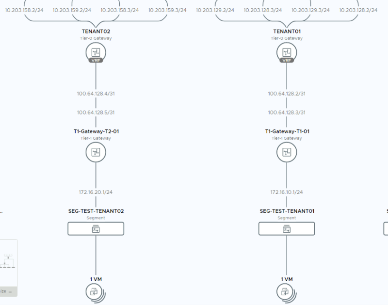
Here you see that the path is taking 5 hops, and when you look at the diagram you see that the "physical network" is used to route the traffic from the TENANT01 VRF to the TENANT02 VRF.
Here you see that the path is taking 5 hops, and when you look at the diagram you see that the "physical network" is used to route the traffic from the TENANT02 VRF to the TENANT01 VRF.
From TENANT02-TEST-VM (172.16.20.11) to TENANT01-TIER-1 GATEWAY DOWNLINK IP (172.16.10.1):
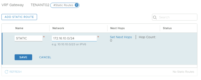
To get routing working between the VRF enabled networks (172.16.10.0/24 and 172.16.20.0/24) using Route leaking it is important to first look at the figure below:
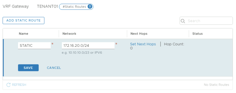
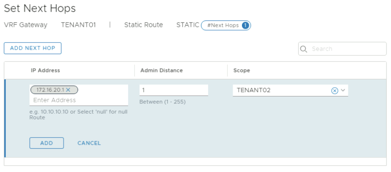
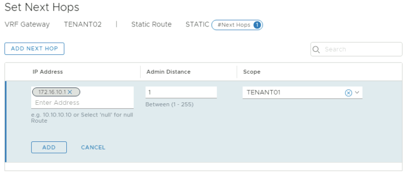
In the diagram take note of the 100.64.128.3/31 and 172.16.10.1/24 (Tenant 1) and 100.64.128.5/31 and 172.16.20.1/24 (Tenant 2) IP addresses. We need to use (one of) these IP addresses as the next-hop IP addresses in a static route we define on the VRF enabled Tier-0 Gateways.
In the screenshots below I have used the IP address 172.16.10.1/24 and 172.16.20.1/24 in the next-hop address for the static route, but this could mind as well be the 100.64.128.3/31 and 100.64.128.5/31 IP addresses.
On the Tier-0 VRF enabled Gateway for TENANT01:
On the Tier-0 VRF enabled Gateway for TENANT02:
Now that the static routes are in I I executed another "tracepath" command from the tenant VM's towards the Tier-1 Segment Gateway IP address:
Here you see that the path is taking 3 hops, and when you look at the diagram you see that the "VRF leaking" is used to route the traffic from the TENANT01 VRF to the TENANT02 VRF.
From TENANT01-TEST-VM (172.16.10.11) to TENANT02-TIER-1 GATEWAY DOWNLINK IP (172.16.20.1):
Here you see that the path is taking 3 hops, and when you look at the diagram you see that the "VRF leaking" is used to route the traffic from the TENANT02 VRF to the TENANT01 VRF.
From TENANT02-TEST-VM (172.16.20.11) to TENANT01-TIER-1 GATEWAY DOWNLINK IP (172.16.10.1):
End–to–end testing with the tenant Virtual Machines
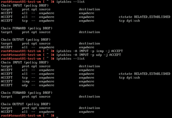
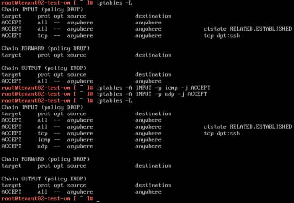
Because I am using Photon OS I first need to open up some INBOUND IPTABLE rules on the Tenant Virtual Machines to allow ping and traceroute/tracepath.
TENANT01-TEST-VM
TENANT02-TEST-VM
Withouth VRF leaking
Now that the IPTABLE rules are in we can test the hops using tracepath. Here you see that it takes 6 hops to go from the TENANT01-TEST-VM to the TENANT02-TEST-VM.
From TENANT01-TEST-VM (172.16.10.11) to TENANT02-TEST-VM (172.16.20.11):
On the return path, you also see that it takes 6 hops to go from the TENANT02-TEST-VM to the TENANT01-TEST-VM.
From TENANT02-TEST-VM (172.16.20.11) to TENANT01-TEST-VM (172.16.10.11):
With VRF leaking
With VRF leaking enabled (so I added the static routes as described here) you see that it takes 4 hops to go from the TENANT01-TEST-VM to the TENANT02-TEST-VM.
From TENANT01-TEST-VM (172.16.10.11) to TENANT02-TEST-VM (172.16.20.11):
On the return path, you also see that it takes 4 hops to go from the TENANT02-TEST-VM to the TENANT01-TEST-VM.
From TENANT02-TEST-VM (172.16.20.11) to TENANT01-TEST-VM (172.16.10.11):
I am always trying to improve the quality of my articles so if you see any errors, mistakes in this article or you have suggestions for improvement, please contact me and I will fix this.
