DVS NIC teaming load balancing options and NSX interoperability
When we set up NSX one of the components that need to be installed at some point is a VTEP network adapter. This VTEP network adapter is nothing more than a virtual (vmk) network adapter on the host that is responsible to encapsulate "normal" network packets into VXLAN network packets (or the other way around). These VTEP's will use the existing vNIC uplinks that are currently configured and leveraged by the vSphere Distributed Switch (vDS). In this article I am going to explain what the available options are and how this is used by NSX.
dVS teaming and NSX VMKNic teaming policy mapping
There are various different sources of documentation available form VMware and I noticed that the terminology is not always in sync. To understand this fully I have tried to map everything together to see what statements and settings belong to each other. This is shown in the table below:
| NSX Design Guide Terminology | NSX Install Guide Terminology | NSX Supported | Multiple VTEPs supported | Traffic Flow / Link Usage | Corresponding VMKNic teaming policy |
|---|---|---|---|---|---|
| Route Based on Originating Port | Route based on the originating virtual port | Yes | Yes | Both links active | LOAD BALANCE - SRCID |
| Route Based on Source MAC Hash | Route based on source MAC hash | Yes | Yes | Both links active | LOAD BALANCE - SRCMAC |
| Route Based on IP Hash (Static EtherChannel) | Route based on IP hash | Yes | No | Flow based | STATIC ETHERCHANNEL |
| Explicit Failover Order | Use explicit failover order | Yes | No | One link active | FAILOVER |
| LACP | Not mentioned here | Yes | No | Flow based | ENHANCED LACP |
| Route Based on Physical NIC Load (LBT) | Route based on physical NIC load | No | N/A | N/A | N/A |
ENHANCED LACP is also called LACPv2
On a individual port group level you can override the dVS teaming option, but the recommendation is not to mix these too much
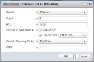
Configure VXLAN Transport Parameters 〈taken from the NSX Installation Guide〉
Plan your NIC teaming policy. Your NIC teaming policy determines the load balancing and failover settings of the vSphere Distributed Switch.
Do not mix different teaming policies for different port groups on a vSphere Distributed Switch where some use Etherchannel or LACPv1 or LACPv2 and others use a different teaming policy. If uplinks are shared in these different teaming policies, traffic will be interrupted. If logical routers are present, there will be routing problems. Such a configuration is not supported and should be avoided.
The best practice for IP hash-based teaming (EtherChannel, LACPv1 or LACPv2) is to use all uplinks on the vSphere Distributed Switch in the team, and do not have port groups on that vSphere Distributed Switch with different teaming policies.
For more information and further guidance, see the VMware® NSX for vSphere Network Virtualization Design Guide at https://communities.vmware.com/docs/DOC-27683.
VDS Uplinks Connectivity NSX Design Considerations 〈taken from the "From the VMware® NSX for vSphere Network Virtualization Design Guide"〉
The teaming option associated to a given port-group must be the same for all the ESXi hosts connected to that specific VDS, even if they belong to separate clusters. For the case of the VXLAN transport port-group, if the LACP teaming option is chosen for the ESXi hosts part of compute cluster, this same option must be applied to all the other compute clusters connected to the same VDS. Selecting a different teaming option for a different cluster would not be accepted and will trigger an error message at the time of VXLAN provisioning.
If LACP or static EtherChannel is selected as the teaming option for VXLAN traffic for clusters belonging to a given VDS, then the same option should be used for all the other port-groups/traffic types defined on the VDS. The EtherChannel teaming choice implies a requirement of additionally configuring a port-channel on the physical network. Once the physical ESXi uplinks are bundled in a port-channel on the physical switch or switches, using a different teaming method on the host side may result in unpredictable results or loss of communication. This is one of the primary reasons that use of LACP is highly discouraged, along with restriction it imposes on Edge VM routing connectivity with proprietary technology such as vPC from Cisco.
The VTEP design impacts the uplink selection choice since NSX supports single or multiple VTEPs configurations. The single VTEP option offers operational simplicity. If traffic requirements are less than 10G of VXLAN traffic per host, then the Explicit Failover Order option is valid. It allows physical separation of the overlay traffic from all the other types of communication; one uplink used for VXLAN, the other uplink for the other traffic types. The use of Explicit Failover Order can also provide applications a consistent quality and experience, independent from any failure. Dedicating a pair of physical uplinks to VXLAN traffic and configuring them as active/standby will guarantee that in the event of physical link or switch failure, applications would still have access to the same 10G pipe of bandwidth. This comes at the price of deploying more physical uplinks and actively using only half of the available bandwidth.
A single VTEP is provisioned in the port-channel scenarios, despite the fact there are two active VDS uplinks. This is because the port-channel is considered a single logical uplink since traffic sourced from the VTEP can be hashed on a per-flow basis across both physical paths.
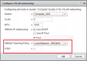
Since the single VTEP is only associated in one uplink in a non port-channel teaming mode, the bandwidth for VXLAN is constrained by the physical NIC speed. If more than 10G of bandwidth is required for workload, multiple VTEPs are required to increase the bandwidth available for VXLAN traffic when the use of port-channels is not possible (e.g., blade servers). Alternately, the VDS uplink configuration can be decoupled from the physical switch configuration. Going beyond two VTEPs (e.g., four uplinks) will results into four VTEP configurations for the host, may be challenging while troubleshooting, and will require a larger IP addressing scope for large-scale L2 design. The number of provisioned VTEPs always matches the number of physical VDS uplinks. This is done automatically once the SRC-ID or SRC-MAC option is selected in the “VMKNic Teaming Policy” section of the UI interface.
The recommended teaming mode for the ESXi hosts in edge clusters is “route based on originating port” while avoiding the LACP or static EtherChannel options. Selecting LACP for VXLAN traffic implies that the same teaming option must be used for all the other port-groups/traffic types which are part of the same VDS. One of the main functions of the edge racks is providing connectivity to the physical network infrastructure. This is typically done using a dedicated VLAN-backed port-group where the NSX Edge handling the north-south routed communication establishes routing adjacencies with the next-hop L3 devices. Selecting LACP or static EtherChannel for this VLAN-backed port-group when the ToR switches perform the roles of L3 devices complicates the interaction between the NSX Edge and the ToR devices.
The ToR switches not only need to support multi-chassis EtherChannel functionality (e.g., vPC or MLAG) but must also be capable of establishing routing adjacencies with the NSX Edge on this logical connection. This creates an even stronger dependency from the underlying physical network device; this may an unsupported configuration in specific cases. As a consequence, the recommendation for edge clusters is to select the SRCID/SRC-MAC hash as teaming options for VXLAN traffic. An architect can also extend this recommended approach for the compute cluster to maintain the configuration consistency, automation ease, and operational troubleshooting experience for all hosts’ uplink connectivity. In summary, the “route based on originating port” is the recommended teaming mode for VXLAN traffic for both compute and edge cluster.
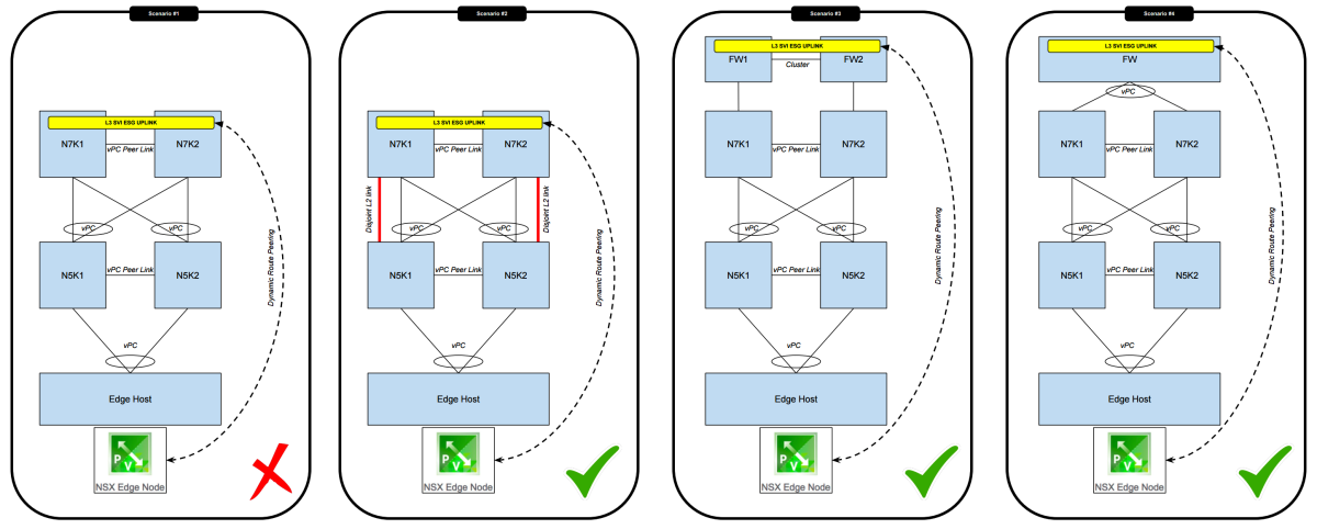
Edge Service Gateway peering across vPC rules
One of the statements above in the NSX Design guide was "Selecting LACP or static EtherChannel for this VLAN-backed port-group when the ToR switches perform the roles of L3 devices complicates the interaction between the NSX Edge and the ToR devices"
The general rules are
- you CANNOT set up a route peering with devices that have an vPC peer link across a vPC Port Channel.
- In order to work around this you can set up separate L2 links (disjoint Layer 2 Links) to allow the peering across these links.
- you CAN set up a route peering with devices ACROSS a vPC Port Channel
Below I have illustrated this:
VMKNic teaming policy
Below you can find the different VMKNic teaming policy options that you are able to select. I have also put together a small summery of the characteristics to get a good feel how this is working and I will back this with some diagrams later in this article.
Load Balance – SRCID
- Multiple VTEP supported
- VTEP to vNIC mapping is1:1
- VM1 with portID=1 will take vNIC0
- VM1 with portID=4 will take vNIC1
- VM2 with portID=2 will take vNIC1
- VM3 with portID=3 will take vNIC0
- The first path chosen will always be valid and does not expire
- The algorithm is round-robin
- This does not take interface load into account
Load Balance – SRCMAC
- Multiple VTEP supported
- VTEP to vNIC mapping is1:1
- VM1 with MAC#1 (eth0.1) will take vNIC0
- VM1 with MAC#2 (eth0.2) will take vNIC1
- VM2 with MAC#2 will take vNIC1
- VM3 with MAC#3 will take vNIC0
- The first path chosen will always be valid and does not expire
- The algorithm is round-robin
- This does not take interface load into account
- This option takes a bit more overhead then SRCID
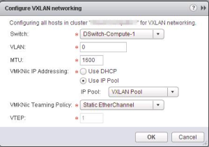
Static Etherchannel
- One VTEP supported
- One interface is only visible (LAG interface)
- The load balancing is taken care of the LACP protocol
- Old version of LACP in dVS version 5.0
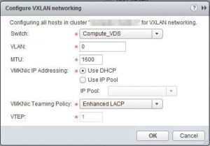
Enhanced LACP 〈LACPv2〉
- One VTEP supported
- One interface is only visible (LAG interface)
- The load balancing is taken care of the LACP protocol
- LACPv1 is not supported
- Old version with less supported load balancing algorithms
- One LAG interface per dVS supported
- One LAG interface per host supported
- LACPv2 = Enhanced LACP
- New version with more supported load balancing algorithms
- 64 LAG interfaces per dVS supported
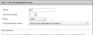
This is the screen to show how the LAG is configured:
Failover
- One VTEP supported
- One interface will always be active and the other always standby
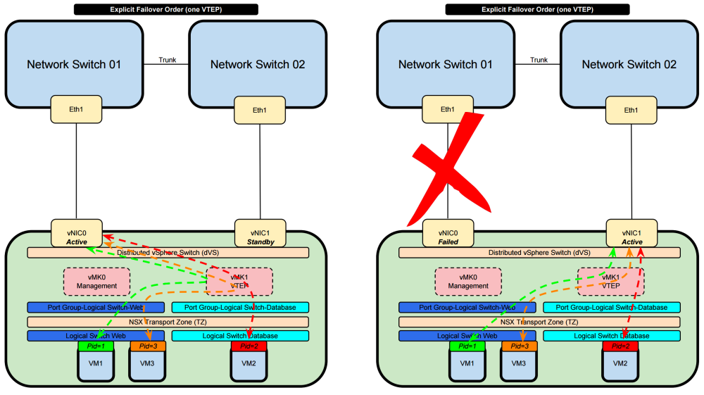
Explicit Failover Order 〈one VTEP〉
- VM1 (with PortID 1) will use the only VTEP interface available and will use the active Physical NIC of the ESXi Host
- VM2 (with PortID 2) will use the only VTEP interface available and will use the active Physical NIC of the ESXi Host
- VM3 (with PortID 3) will use the only VTEP interface available and will use the active Physical NIC of the ESXi Host
- Only one Physical NIC is always active and the other one is standby
- When the active goes down then the standby becomes active and the traffic is forwarded trough that new active interface
- Port ID is not taken into consideration for load sharing / load balancing
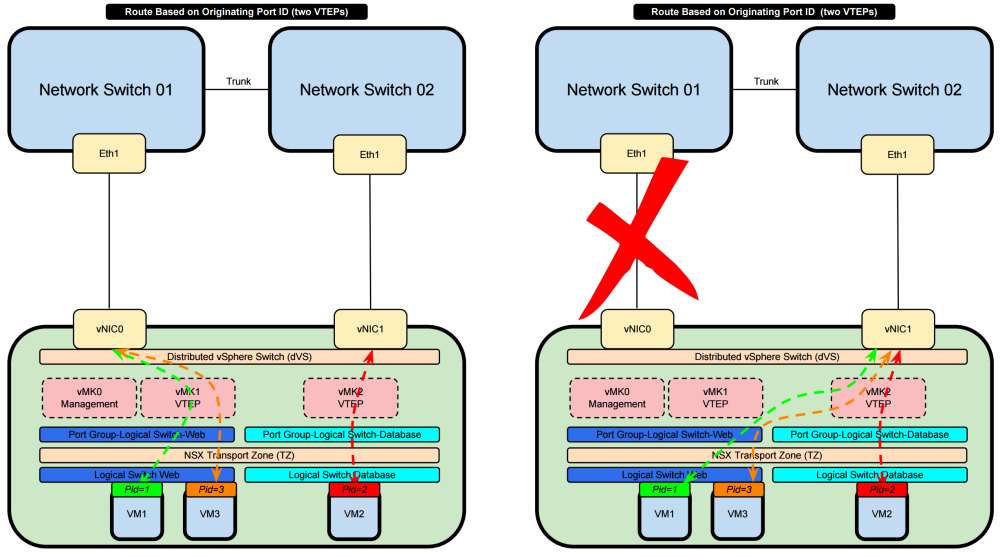
Route Based on Originating Port ID 〈two VTEPs〉
- VM1 (with PortID 1) will use the VTEP1 interface available and will use the Physical NIC 0 of the ESXi Host
- VM2 (with PortID 2) will use the VTEP2 interface available and will use the Physical NIC 1 of the ESXi Host
- VM3 (with PortID 3) will use the VTEP1 interface available and will use the Physical NIC 0 of the ESXi Host
- This goes on-and-on in a Round Robin fashion
- Both physical NICs are active
- When the one physical NIC goes down then the other will be used and the traffic is forwarded trough that available interface
- Port ID is taken into consideration for load sharing / load balancing
- The algorithm does not take interface load into account
- SO if physical NIC0 is overutilized due to al ot of traffic traversing this interface the "Route Based on Originating Port ID" algorithm will still try to use this interface
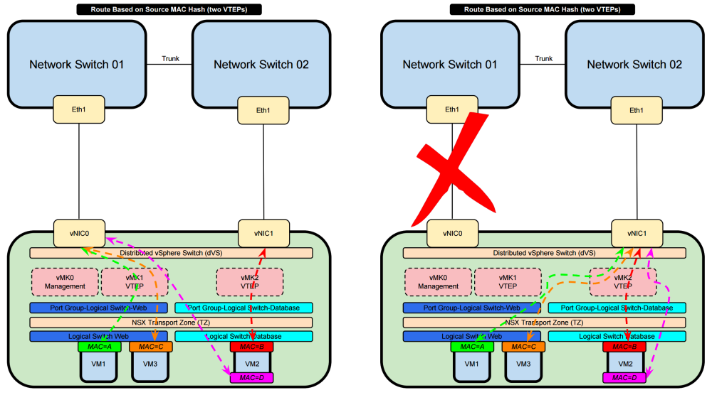
Route Based on Source MAC Hash 〈two VTEPs〉
- VM1 (with MAC A) will use the VTEP1 interface available and will use the Physical NIC 0 of the ESXi Host
- VM2 (with MAC B) will use the VTEP2 interface available and will use the Physical NIC 1 of the ESXi Host
- VM3 (with MAC C) will use the VTEP1 interface available and will use the Physical NIC 0 of the ESXi Host
- VM2 (with MAC D) will use the VTEP1 interface available and will use the Physical NIC 0 of the ESXi Host
- This goes on-and-on in a Round Robin fashion
- VM2 has one virtual NIC with two sub-interfaces and each sub-interface has it's own MAC address
- Both physical NICs are active
- When the one physical NIC goes down then the other will be used and the traffic is forwarded trough that available interface
- MAC Addresses are taken into consideration for load sharing / load balancing
- The algorithm does not take interface load into account
- SO if physical NIC0 is overutilized due to al ot of traffic traversing this interface the "Route Based on Originating Port ID" algorithm will still try to use this interface
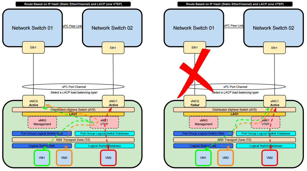
vSphere Networking and NSX – Static EtherChannel and LACP – 1 x VTEP
- With the use of Etherchannel or LACP regardless what version the loadbalancing protocol selected between the vDS and the physical switch will dictate the load balancing way
- Both physical NICs are active
- When the one physical NIC goes down then the other will be used and the traffic is forwarded trough that available interface
vSphere load balancing type support
vSphere supports these load balancing types:
- Destination IP address
- Destination IP address and TCP/UDP port
- Destination IP address and VLAN
- Destination IP address, TCP/UDP port and VLAN
- Destination MAC address
- Destination TCP/UDP port
- Source IP address
- Source IP address and TCP/UDP port
- Source IP address and VLAN
- Source IP address, TCP/UDP port and VLAN
- Source MAC address
- Source TCP/UDP port
- Source and destination IP address
- Source and destination IP address and TCP/UDP port
- Source and destination IP address and VLAN
- Source and destination IP address, TCP/UDP port and VLAN
- Source and destination MAC address
- Source and destination TCP/UDP port
- Source port ID
- VLAN
When LACP is configured the switch that the ESXi host is connected to must match the same load balancing type that is available and selected on the ESXi / dVS side. A mismatch between these two can and will result in the loss of network traffic.
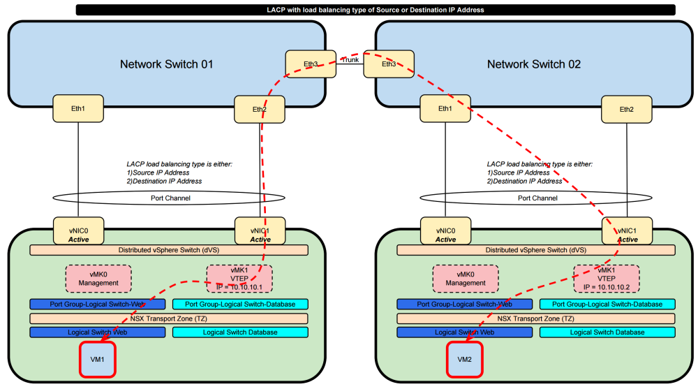
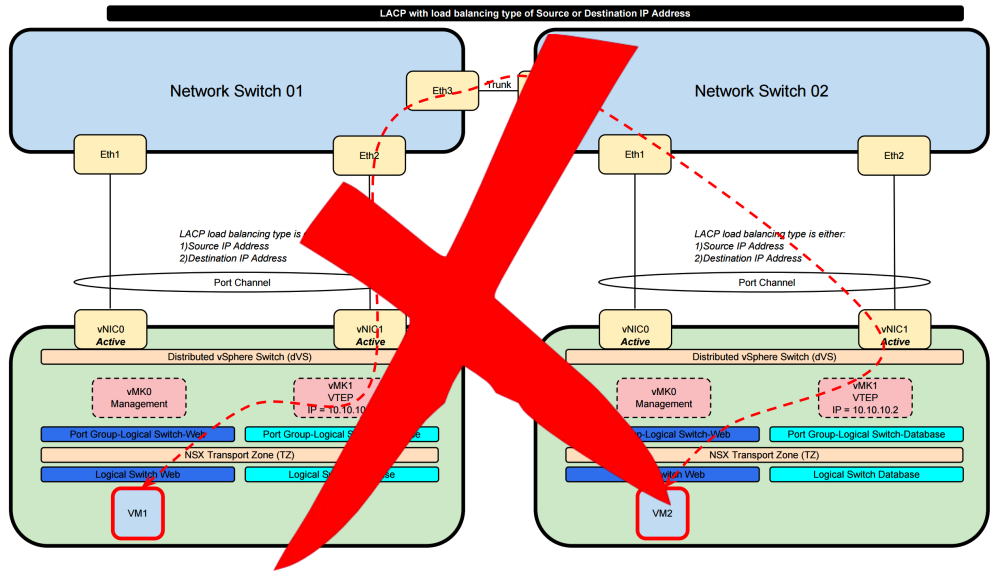
Route Based on IP Hash 〈Static EtherChannel〉 or LACP with the load balancing types» Destination IP address and Source IP address
When we select this option the load sharing of the traffic is determined by the load balancing algorithm that you select on the dVS side and on the physical network side. When we select the load balancing type to be "Destination IP address" or "Source IP address" with VTEP traffic are some drawbacks.
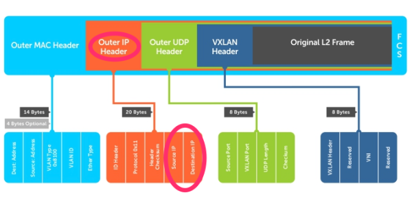
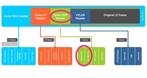
This is how the VXLAN frame format looks like:
When the LACP load balancing is done based on either the Destination IP address or the Source IP address it will use the “Outer IP Header” into consideration to make the load balancing decisions. Specifically for NSX it will use the IP addresses of the VTEP interfaces as te source or destination. These IP addresses typically never change. This means that the traffic path chosen will ALWAYS use the same links and no load balancing will take place for VXLAN based traffic (traffic that is originated from and to a NSX Logical Switch).
So this combination is not usable and will not give you what you want.
In order to “solve” this it is better good to use a load balancing type that takes Layer 4 (protocol information UDP/TCP port information) into consideration. This way load balancing will be based on more dynamic elements.
Other Documentation Sources
- NSX and teaming policy
- vSphere (6) vDS Teaming and Failover Policies
- vDS LACPv1 and LACPv2 differences explanation
- NIC teaming in ESXi and ESX (1004088)
- LACP ON VSPHERE 6.0 AND CISCO
- Link Aggregation Control Protocol (LACP) with VMware vSphere 5.1.x, 5.5.x and 6.x (2120663)
- Enhanced LACP Support on a vSphere 5.5 Distributed Switch (2051826)
- Understanding IP Hash load balancing (2006129)
