Create an NSX-T manager node cluster: Difference between revisions
No edit summary |
|||
| (4 intermediate revisions by 2 users not shown) | |||
| Line 1: | Line 1: | ||
In this article, I will explain to you the different options of how you can design and deploy an NSX-T manager node cluster. I will provide you all the different options with justifications of why one choice is better than the other one. I will also discuss the risks that are introduced when you choose a specific option if they are any. | In this article, I will explain to you the different options of how you can design and deploy an NSX-T manager node cluster. I will provide you all the different options with justifications of why one choice is better than the other one. I will also discuss the risks that are introduced when you choose a specific option if they are any. | ||
Below you will find the NSX-T Manager cluster options | |||
==One single NSX | ==One single NSX–T Manager node== | ||
{{note|This is not an NSX-T cluster, but I wanted to show you how it looks like when you don’t have any NSX-T Manager node cluster. So this is your starting point.}} | {{note|This is not an NSX-T cluster, but I wanted to show you how it looks like when you don’t have any NSX-T Manager node cluster. So this is your starting point.}} | ||
| Line 28: | Line 26: | ||
|} | |} | ||
<span style="border:3px solid | <span style="border:3px solid #f4c613;display: inline-block;">[[File:Nsxt-manager-cluster-01.png|700px]]</span> | ||
<div style="clear:both"></div> | <div style="clear:both"></div> | ||
==The three | ==The three–node NSX–T Manager cluster== | ||
===VIP IP address with the three | ===VIP IP address with the three–node NSX–T Manager cluster=== | ||
The NSX-T cluster has the option to configure a VIP address across the three NSX-T manager nodes. When the NSX-T Manager VIP address option is chosen, the IP address on the NSX-T manager needs to be in the same subnet. | The NSX-T cluster has the option to configure a VIP address across the three NSX-T manager nodes. When the NSX-T Manager VIP address option is chosen, the IP address on the NSX-T manager needs to be in the same subnet. | ||
| Line 46: | Line 44: | ||
<span style="border:3px solid | <span style="border:3px solid #f4c613;display: inline-block;">[[File:Chapter 02-NSX-T Management Cluster VIP.png|700px]]</span> | ||
<div style="clear:both"></div> | <div style="clear:both"></div> | ||
===The three | ===The three–node NSX–T Manager cluster with an 〈external Load Balancer〉=== | ||
Another option to balance the load between the NSX-T Managers inside the NSX-T manager cluster is to make use of a load balancer. This load balancer can be either a third-party load balancer or an NSX load balancer from a different NSX-T deployment. | Another option to balance the load between the NSX-T Managers inside the NSX-T manager cluster is to make use of a load balancer. This load balancer can be either a third-party load balancer or an NSX load balancer from a different NSX-T deployment. | ||
| Line 57: | Line 55: | ||
<span style="border:3px solid | <span style="border:3px solid #f4c613;display: inline-block;">[[File:Chapter 02-NSX-T Management Cluster LB.png|700px]]</span> | ||
<div style="clear:both"></div> | <div style="clear:both"></div> | ||
==The placement of the nodes== | ==The placement of the nodes== | ||
===OPTION 1 | ===OPTION 1{{fqm}} Placing the NSX–T manager nodes on a single ESXi host=== | ||
{| class="wikitable" | {| class="wikitable" | ||
| Line 83: | Line 81: | ||
|} | |} | ||
<span style="border:3px solid | <span style="border:3px solid #f4c613;display: inline-block;">[[File:Drawings-single_site_option_2.png|700px]]</span> | ||
<div style="clear:both"></div> | <div style="clear:both"></div> | ||
===OPTION 2 | ===OPTION 2{{fqm}} Placing the NSX–T manager nodes on three different hosts on one single vSphere cluster=== | ||
====Single Rack==== | ====Single Rack==== | ||
| Line 111: | Line 109: | ||
{{important|Notice that the vSphere Clusters on the figure below are not stretched across the racks but are configured to have one single vSphere Cluster per Rack, for me, this is typically not something I would do, but there may be a requirement or constraint in your deployment that you need to do it like this.}} | {{important|Notice that the vSphere Clusters on the figure below are not stretched across the racks but are configured to have one single vSphere Cluster per Rack, for me, this is typically not something I would do, but there may be a requirement or constraint in your deployment that you need to do it like this.}} | ||
<span style="border:3px solid | <span style="border:3px solid #f4c613;display: inline-block;">[[File:Drawings-single site option 3.2.png|700px]]</span> | ||
<div style="clear:both"></div> | <div style="clear:both"></div> | ||
| Line 135: | Line 133: | ||
|} | |} | ||
<span style="border:3px solid | <span style="border:3px solid #f4c613;display: inline-block;">[[File:Drawings-single site option 4.png|700px]]</span> | ||
<div style="clear:both"></div> | <div style="clear:both"></div> | ||
===OPTION 3 | ===OPTION 3{{fqm}} Placing the NSX–T manager nodes on three different hosts on three different vSphere clusters=== | ||
====Single Rack==== | ====Single Rack==== | ||
| Line 162: | Line 160: | ||
|} | |} | ||
<span style="border:3px solid | <span style="border:3px solid #f4c613;display: inline-block;">[[File:Drawings-single site option 3.1.png|700px]]</span> | ||
<div style="clear:both"></div> | <div style="clear:both"></div> | ||
| Line 186: | Line 184: | ||
|} | |} | ||
<span style="border:3px solid | <span style="border:3px solid #f4c613;display: inline-block;">[[File:Drawings-single site option 4 (1).png|700px]]</span> | ||
<div style="clear:both"></div> | <div style="clear:both"></div> | ||
===OPTION 4 | ===OPTION 4{{fqm}} Placing the NSX–T manager nodes spread across two sites using a stretched vSphere Cluster=== | ||
{| class="wikitable" | {| class="wikitable" | ||
| Line 210: | Line 208: | ||
|} | |} | ||
<span style="border:3px solid | <span style="border:3px solid #f4c613;display: inline-block;">[[File:Drawings-dual site option 1.1.png|700px]]</span> | ||
<div style="clear:both"></div> | <div style="clear:both"></div> | ||
{{note|The figure below will have the same result as the figure above, but the majority of the NSX-T Manager nodes are now placed on the DC-B side.}} | {{note|The figure below will have the same result as the figure above, but the majority of the NSX-T Manager nodes are now placed on the DC-B side.}} | ||
<span style="border:3px solid | <span style="border:3px solid #f4c613;display: inline-block;">[[File:Drawings-dual site option 1.2.png|700px]]</span> | ||
<div style="clear:both"></div> | <div style="clear:both"></div> | ||
| Line 225: | Line 223: | ||
}} | }} | ||
===OPTION 5 | ===OPTION 5{{fqm}} Placing the NSX–T manager nodes spread across two sites using different vSphere Clusters=== | ||
{| class="wikitable" | {| class="wikitable" | ||
| Line 246: | Line 244: | ||
|} | |} | ||
<span style="border:3px solid | <span style="border:3px solid #f4c613;display: inline-block;">[[File:Drawings-dual site option 2.1.png|700px]]</span> | ||
<div style="clear:both"></div> | <div style="clear:both"></div> | ||
{{note|The figure below will have the same result as the figure above, but the majority of the NSX-T Manager nodes are now placed on the DC-B side.}} | {{note|The figure below will have the same result as the figure above, but the majority of the NSX-T Manager nodes are now placed on the DC-B side.}} | ||
<span style="border:3px solid | <span style="border:3px solid #f4c613;display: inline-block;">[[File:Drawings-dual site option 2.2.png|700px]]</span> | ||
<div style="clear:both"></div> | <div style="clear:both"></div> | ||
| Line 261: | Line 259: | ||
}} | }} | ||
===OPTION 6 | ===OPTION 6{{fqm}} Placing the NSX–T manager nodes spread across three sites using a stretched vSphere Cluster=== | ||
{| class="wikitable" | {| class="wikitable" | ||
| Line 282: | Line 280: | ||
|} | |} | ||
<span style="border:3px solid | <span style="border:3px solid #f4c613;display: inline-block;">[[File:Drawings-tripple site option 1.1.png|700px]]</span> | ||
<div style="clear:both"></div> | <div style="clear:both"></div> | ||
| Line 292: | Line 290: | ||
}} | }} | ||
===OPTION 7 | ===OPTION 7{{fqm}} Placing the NSX–T manager nodes spread across three sites using three different vSphere Clusters=== | ||
{| class="wikitable" | {| class="wikitable" | ||
| Line 313: | Line 311: | ||
|} | |} | ||
<span style="border:3px solid | <span style="border:3px solid #f4c613;display: inline-block;">[[File:Drawings-tripple site option 1.2.png|700px]]</span> | ||
<div style="clear:both"></div> | <div style="clear:both"></div> | ||
| Line 323: | Line 321: | ||
}} | }} | ||
= | =The best option= | ||
When you look at the above options, there are pros and cons to each option. This makes it hard to choose, and your constraints often determine the choice. | When you look at the above options, there are pros and cons to each option. This makes it hard to choose, and your constraints often determine the choice. | ||
| Line 347: | Line 345: | ||
|- | |- | ||
| Bode Fatona || [https://www.linkedin.com/in/bode-fatona-2602ba1/ Link] | | Bode Fatona || [https://www.linkedin.com/in/bode-fatona-2602ba1/ Link] | ||
|} | |} | ||
I am always trying to improve the quality of my articles so if you see any errors, mistakes in this article or you have suggestions for improvement, [[Special:Contact|please contact me]] and I will fix this. | I am always trying to improve the quality of my articles so if you see any errors, mistakes in this article or you have suggestions for improvement, [[Special:Contact|please contact me]] and I will fix this. | ||
[[Category:NSX | [[Category: NSX]] | ||
[[Category: | [[Category:Networking]] | ||
[[Category:VMware]] | |||
Latest revision as of 19:20, 16 March 2024
In this article, I will explain to you the different options of how you can design and deploy an NSX-T manager node cluster. I will provide you all the different options with justifications of why one choice is better than the other one. I will also discuss the risks that are introduced when you choose a specific option if they are any.
Below you will find the NSX-T Manager cluster options
One single NSX–T Manager node
This is not an NSX-T cluster, but I wanted to show you how it looks like when you don’t have any NSX-T Manager node cluster. So this is your starting point.
| Design option description | In this design option, you will only have one NSX-T manager node deployed on one single ESXi host. |
| Design justification(s) | This is a typical design that you can use in a Proof of Concept (PoC) environment where you don’t require and redundancy or fast recovery in case a failure occurs. |
| Design risk(s) | The risk with this design option is that you only have one NSX-T manager, and if this NSX-T manager fails, you can not make changes to your NSX-T network and security infrastructure. This risk can be mitigated by performing backups periodically and restore from the backup when this is required. |
| Design implication | There is no redundancy of the NSX-T Manager, and restoring from a backup takes longer than having the NSX-T Managers highly available. |
| Design quality | Availability, Manageability, Performance, and Recoverability. |
| VIP IP address | N/A |
| external Load Balancer | N/A |
The three–node NSX–T Manager cluster
VIP IP address with the three–node NSX–T Manager cluster
The NSX-T cluster has the option to configure a VIP address across the three NSX-T manager nodes. When the NSX-T Manager VIP address option is chosen, the IP address on the NSX-T manager needs to be in the same subnet. The example below shows you that all the NSX-T Manager IP addresses, including the VIP address, is in the 10.10.10.0/24 network. NSX-T GUI/API network traffic is not balanced across the NSX-T manager nodes when the VIP address is used. One NSX-T Manager will be chosen by the NSX-T cluster to be the “leader manager”. Once the leader has been selected, the NSX-T VIP address will forward all the traffic to the “leader manager”. The other two NSX-T managers will not receive an incoming query as the VIP IP address entirely handles the management communication. If the leader fails, the two remaining managers elect a new leader. The new leader responds to the requests sent to that virtual IP address.
When the leader node that owns the VIP IP address fails, a new leader is chosen. This new leader will send out a Gratuitous Address Resolution Protocol (GARP) request to take ownership of the VIP. The new NSX-T leader node then receives the new API and GUI requests from users.
Even though the NSX-T manager cluster is using a VIP IP address, each individual NSX-T manager can still be accessed directly. The figure below shows that, from the administrator’s perspective, a single IP address (the virtual IP address) is always used to access the NSX management cluster.
The three–node NSX–T Manager cluster with an 〈external Load Balancer〉
Another option to balance the load between the NSX-T Managers inside the NSX-T manager cluster is to make use of a load balancer. This load balancer can be either a third-party load balancer or an NSX load balancer from a different NSX-T deployment. When you terminate on the VIP IP address that is now hosted by the load balancer, you can place each NSX-T Manager node in different subnets. The example below shows you that all the NSX-T Manager IP addresses are in the 10.10.20.0/24, 10.10.30.0/24, and 10.10.40.0/24 network. Each NSX-T Manager node will be active, and the traffic that is load-balanced by the load balancer will send traffic to multiple nodes based on the load balancing algorithm.
The placement of the nodes
OPTION 1» Placing the NSX–T manager nodes on a single ESXi host
| Design option description | In this design option, you will have three NSX-T manager nodes deployed on one single ESXi host. |
| Design justification(s) | This is a typical design that you can use in a Proof of Concept (PoC) environment where you want to test the NSX-T CLuster nodes configuration. |
| Design risk(s) | When you put all your NSX-T manager nodes on a single ESXi host, there is a risk that if this ESXi host goes down, you can not make changes to your NSX-T network and security infrastructure. This risk can be mitigated by performing backups periodically and restore from the backup when this is required or by spreading the NSX-T nodes across different ESXi hosts across different racks, Data Centers, and/or vSphere CLusters (all described below). |
| Design implication | When the ESXi host goes down hosting all the NSX-T manager nodes, you lose the full management/control plane. |
| Design quality | Availability, Manageability, Performance, and Recoverability. |
| VIP IP address | The NSX-T VIP address can be configured when you host the NSX-T Manager nodes are on the same subnet. |
| external Load Balancer | The external load balancer can be configured, but you need to have an external load balancer pre-configured for this purpose. |
OPTION 2» Placing the NSX–T manager nodes on three different hosts on one single vSphere cluster
Single Rack
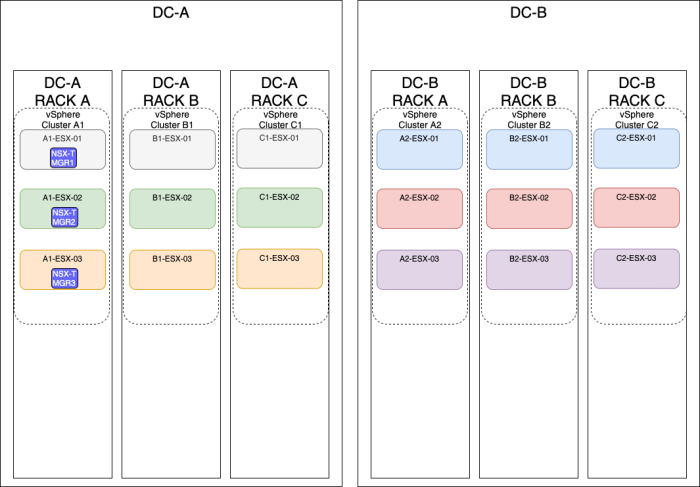
| Design option description | In this design option, you will have three NSX-T manager nodes deployed on three different ESXi hosts, but these hosts are all in one single vSphere cluster in one single Rack. |
| Design justification(s) | This is a typical design that you can use in a Production environment when you only have one Rack and one vSphere cluster available as a constraint. |
| Design risk(s) | The risk with this design is that when the Rack fails you lose the full Management/control plane, and you also lose your Management/control plane when a cluster fails (due to a vSphere cluster-wide issue causing all the ESXi hosts in the cluster to go down with a Purple Screen of Death (PSoD)). You can mitigate this risk by spreading your NSX-T manager nodes across multiple racks and/or vSphere Clusters (like described in this article as well). |
| Design implication | When the Rack and/or vSphere Cluster goes down hosting all the NSX-T manager nodes, you lose the full management/control plane. |
| Design quality | Availability, Manageability, Performance, and Recoverability. |
| VIP IP address | The NSX-T VIP address can be configured when you host the NSX-T Manager nodes are on the same subnet. |
| external Load Balancer | The external load balancer can be configured, but you need to have an external load balancer pre-configured for this purpose. |
Notice that the vSphere Clusters on the figure below are not stretched across the racks but are configured to have one single vSphere Cluster per Rack, for me, this is typically not something I would do, but there may be a requirement or constraint in your deployment that you need to do it like this.
Multiple Racks
| Design option description | In this design option, you will have three NSX-T manager nodes deployed on three different ESXi hosts, these hosts are all in one single vSphere cluster spread across multiple racks. |
| Design justification(s) | This is a typical design that you can use in a Production environment when you only have multiple racks. |
| Design risk(s) | The risk with this design is that when a cluster fails (due to a vSphere cluster-wide issue causing all the ESXi hosts in the cluster to go down with a Purple Screen of Death (PSoD)). You can mitigate this risk by spreading your NSX-T manager nodes across multiple racks and/or vSphere Clusters (like described in this article as well). |
| Design implication | When the vSphere Cluster goes down hosting all the NSX-T manager nodes, you lose the full management/control plane. |
| Design quality | Availability, Manageability, Performance, and Recoverability. |
| VIP IP address | The NSX-T VIP address can be configured when you host the NSX-T Manager nodes are on the same subnet. |
| external Load Balancer | The external load balancer can be configured, but you need to have an external load balancer pre-configured for this purpose. |
OPTION 3» Placing the NSX–T manager nodes on three different hosts on three different vSphere clusters
Single Rack
| Design option description | In this design option, you will have three NSX-T manager nodes deployed on three different ESXi hosts, but these hosts are all in one single Rack. |
| Design justification(s) | This is a typical design that you can use in a Production environment when you only have one Rack available as a constraint. |
| Design risk(s) | The risk with this design is that when the Rack fails, you lose the full Management/control plane. You can mitigate this risk by spreading your NSX-T manager nodes across multiple racks and/or vSphere Clusters (like described in this article as well). |
| Design implication | When the Rack goes down hosting all the NSX-T manager nodes, you lose the full management/control plane. |
| Design quality | Availability, Manageability, Performance, and Recoverability. |
| VIP IP address | The NSX-T VIP address can be configured when you host the NSX-T Manager nodes are on the same subnet. |
| external Load Balancer | The external load balancer can be configured, but you need to have an external load balancer pre-configured for this purpose. |
Multiple Racks
| Design option description | In this design option, you will have three NSX-T manager nodes deployed on three different ESXi hosts, using different vSphere Clusters and different racks. |
| Design justification(s) | This is a typical design that you can use in a Production environment when you only have multiple racks available and multiple vSphere clusters available. |
| Design risk(s) | The risk with this design is that from a management perspective, you are using a lot of management resources resulting in an expensive management infrastructure environment. You need to make a tradeoff between redundancy/availability and cost here. |
| Design implication | This solution brings a lot of management complexity and cost more compared to other solutions if you consider the VCF ground rules where you require four Management Hosts inside a (Management) cluster. |
| Design quality | Availability, Manageability, Performance, and Recoverability. |
| VIP IP address | The NSX-T VIP address can be configured when you host the NSX-T Manager nodes are on the same subnet. |
| external Load Balancer | The external load balancer can be configured, but you need to have an external load balancer pre-configured for this purpose. |
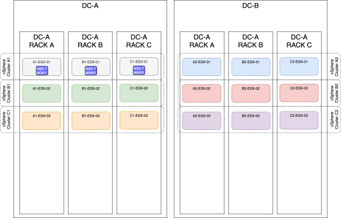
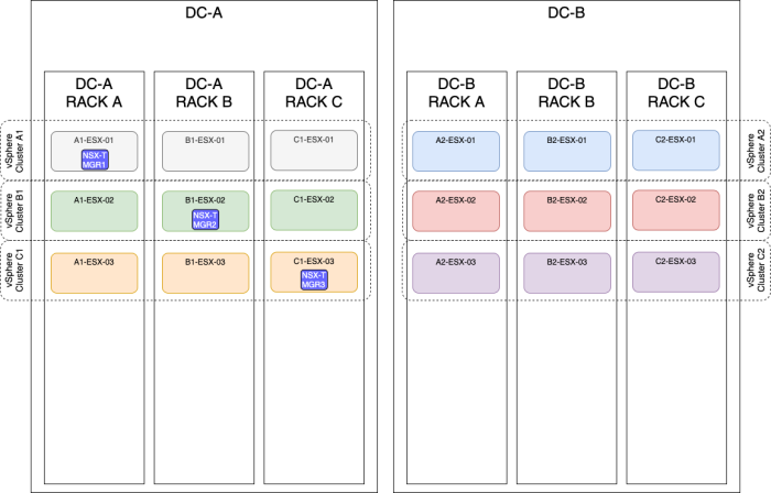
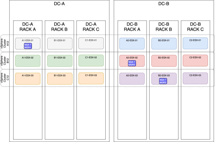
OPTION 4» Placing the NSX–T manager nodes spread across two sites using a stretched vSphere Cluster
| Design option description | In this design option, you will have three NSX-T manager nodes deployed on three different ESXi hosts, these hosts are all in one single vSphere cluster spread across multiple racks and multiple sites (Metropolitan Regions). |
| Design justification(s) | This is a typical design that you can use in a Production environment when you only have multiple racks and multiple sites(2). |
| Design risk(s) | The risk with this design is that when a cluster fails (due to a vSphere cluster-wide issue causing all the ESXi hosts in the cluster to go down with a Purple Screen of Death (PSoD)). You can mitigate this risk by spreading your NSX-T manager nodes across multiple racks and/or vSphere Clusters (like described in this article as well). |
| Design implication | When the vSphere Cluster goes down hosting all the NSX-T manager nodes, you lose the full management/control plane. |
| Design quality | Availability, Manageability, Performance, and Recoverability. |
| VIP IP address | The NSX-T VIP address can be configured when you host the NSX-T Manager nodes are on the same subnet. |
| external Load Balancer | The external load balancer can be configured, but you need to have an external load balancer pre-configured for this purpose. |
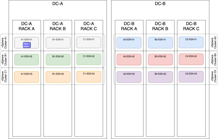
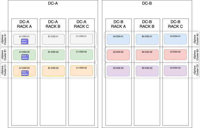
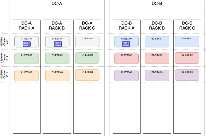
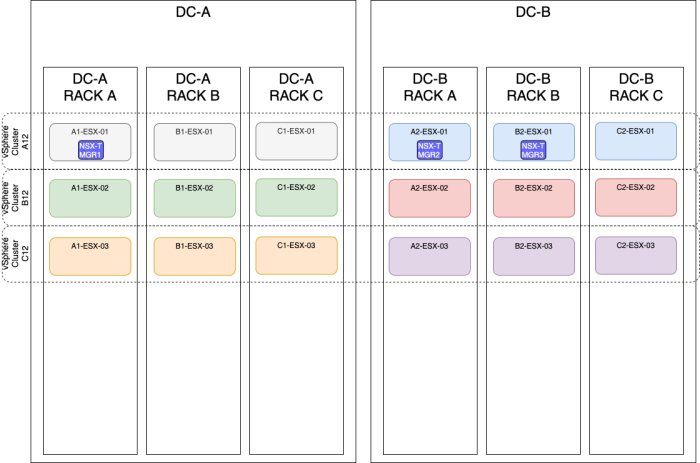
The figure below will have the same result as the figure above, but the majority of the NSX-T Manager nodes are now placed on the DC-B side.
- Resilient storage is recommended.
- Maximum latency between nodes and Transport Nodes (Host or Edge) is 150 milliseconds or less.
- Maximum Network Latency between NSX-T Management Nodes is ten milliseconds or less.
- Splitting manager node across sites with high latency not supported.
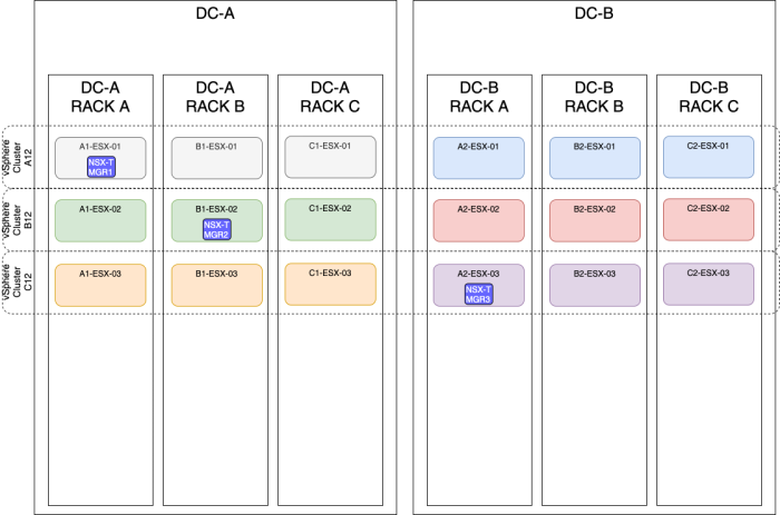
OPTION 5» Placing the NSX–T manager nodes spread across two sites using different vSphere Clusters
| Design option description | In this design option, you will have three NSX-T manager nodes deployed on three different ESXi hosts, using different vSphere Clusters and different racks spread across multiple sites (Metropolitan Regions). |
| Design justification(s) | This is a typical design that you can use in a Production environment when you only have multiple racks available and multiple vSphere clusters available and various sites(2). |
| Design risk(s) | The risk with this design is that from a management perspective, you are using a lot of management resources resulting in an expensive management infrastructure environment. You need to make a tradeoff between redundancy/availability and cost here. |
| Design implication | This solution brings a lot of management complexity and cost more compared to other solutions if you consider the VCF ground rules where you require four Management Hosts inside a (Management) cluster. |
| Design quality | Availability, Manageability, Performance, and Recoverability. |
| VIP IP address | The NSX-T VIP address can be configured when you host the NSX-T Manager nodes are on the same subnet. |
| external Load Balancer | The external load balancer can be configured, but you need to have an external load balancer pre-configured for this purpose. |
The figure below will have the same result as the figure above, but the majority of the NSX-T Manager nodes are now placed on the DC-B side.
- Resilient storage is recommended.
- Maximum latency between nodes and Transport Nodes (Host or Edge) is 150 milliseconds or less.
- Maximum Network Latency between NSX-T Management Nodes is ten milliseconds or less.
- Splitting manager node across sites with high latency not supported.
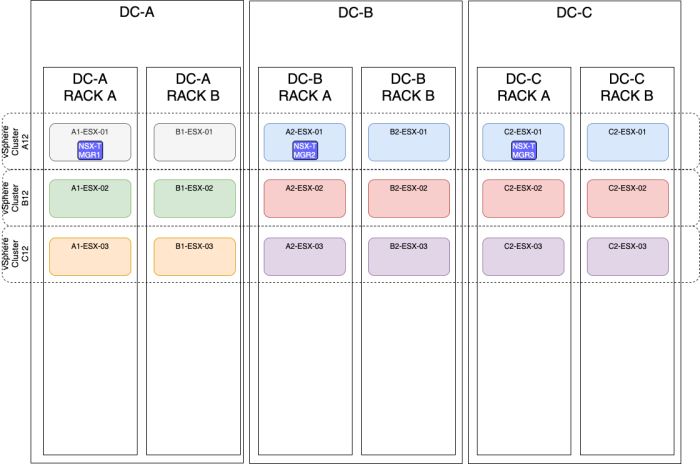
OPTION 6» Placing the NSX–T manager nodes spread across three sites using a stretched vSphere Cluster
| Design option description | In this design option, you will have three NSX-T manager nodes deployed on three different ESXi hosts, these hosts are all in one single vSphere cluster spread across multiple racks and multiple sites (Metropolitan Regions). |
| Design justification(s) | This is a typical design that you can use in a Production environment when you only have multiple racks and multiple sites(3). |
| Design risk(s) | The risk with this design is that when a cluster fails (due to a vSphere cluster-wide issue causing all the ESXi hosts in the cluster to go down with a Purple Screen of Death (PSoD)). You can mitigate this risk by spreading your NSX-T manager nodes across multiple vSphere Clusters (like described in this article as well). |
| Design implication | When the vSphere Cluster goes down hosting all the NSX-T manager nodes, you lose the full management/control plane. |
| Design quality | Availability, Manageability, Performance, and Recoverability. |
| VIP IP address | The NSX-T VIP address can be configured when you host the NSX-T Manager nodes are on the same subnet. |
| external Load Balancer | The external load balancer can be configured, but you need to have an external load balancer pre-configured for this purpose. |
- Resilient storage is recommended.
- Maximum latency between nodes and Transport Nodes (Host or Edge) is 150 milliseconds or less.
- Maximum Network Latency between NSX-T Management Nodes is ten milliseconds or less.
- Splitting manager node across sites with high latency not supported.
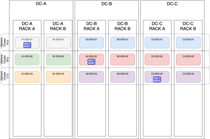
OPTION 7» Placing the NSX–T manager nodes spread across three sites using three different vSphere Clusters
| Design option description | In this design option, you will have three NSX-T manager nodes deployed on three different ESXi hosts, using different vSphere Clusters and different racks spread across multiple sites (Metropolitan Regions). |
| Design justification(s) | This is a typical design that you can use in a Production environment when you only have multiple racks available and multiple vSphere clusters available and various sites(3). |
| Design risk(s) | The risk with this design is that from a management perspective, you are using a lot of management resources resulting in an expensive management infrastructure environment. You need to make a tradeoff between redundancy/availability and cost here. |
| Design implication | This solution brings a lot of management complexity and cost more compared to other solutions if you consider the VCF ground rules where you require four Management Hosts inside a (Management) cluster. |
| Design quality | Availability, Manageability, Performance, and Recoverability. |
| VIP IP address | The NSX-T VIP address can be configured when you host the NSX-T Manager nodes are on the same subnet. |
| external Load Balancer | The external load balancer can be configured, but you need to have an external load balancer pre-configured for this purpose. |
- Resilient storage is recommended.
- Maximum latency between nodes and Transport Nodes (Host or Edge) is 150 milliseconds or less.
- Maximum Network Latency between NSX-T Management Nodes is ten milliseconds or less.
- Splitting manager node across sites with high latency not supported.
The best option
When you look at the above options, there are pros and cons to each option. This makes it hard to choose, and your constraints often determine the choice. But if you ask me, you should always design for at least one failure on multiple levels, so a host, Rack, vSphere Cluster, and site failure. This will eventually lead you to a design where you spread your NSX-T Manager nodes across multiple hosts, racks, vSphere Clusters, and Sites (so OPTION 5 or OPTION 7). But this introduces other risks that are related to management complexity and cost.
YouTube Videos
In the video below I will show you how to Create an NSX-T Manager Node Cluster:
In the video below I will show you how to Configure the VIP IP address on an NSX-T Cluster:
Technical Reviews
This article was technically reviewed by the following SME's:
| Name | LinkedIn Profile |
|---|---|
| Bode Fatona | Link |
I am always trying to improve the quality of my articles so if you see any errors, mistakes in this article or you have suggestions for improvement, please contact me and I will fix this.
