Configure NSX-T Logical Bridging (single profile): Difference between revisions
m (Change span border color) |
m (Applying replacements) |
||
| (One intermediate revision by one other user not shown) | |||
| Line 27: | Line 27: | ||
=The configuration steps= | =The configuration steps= | ||
==STEP 1 | ==STEP 1{{fqm}} Create vDS Bridge Port–Group 〈TRUNK〉== | ||
First, we need to create a VDS port group (on vSphere) that we will use for the Edge transport Node so that it can map one of the fast-path interfaces to this port group. | First, we need to create a VDS port group (on vSphere) that we will use for the Edge transport Node so that it can map one of the fast-path interfaces to this port group. | ||
| Line 68: | Line 68: | ||
<span style="border:3px solid #f4c613;display: inline-block;">[[File:CREATE-BRIDGE-PG-9.png|600px]]</span> | <span style="border:3px solid #f4c613;display: inline-block;">[[File:CREATE-BRIDGE-PG-9.png|600px]]</span> | ||
==STEP 2 | ==STEP 2{{fqm}} Create a new NSX–T Transport Zone 〈dedicated for the bridge interface〉== | ||
Add a new Transport Zone dedicated to bridging. | Add a new Transport Zone dedicated to bridging. | ||
| Line 81: | Line 81: | ||
<span style="border:3px solid #f4c613;display: inline-block;">[[File:CREATE-BRIDGE-TZ-2.png|800px]]</span> | <span style="border:3px solid #f4c613;display: inline-block;">[[File:CREATE-BRIDGE-TZ-2.png|800px]]</span> | ||
==STEP 3 | ==STEP 3{{fqm}} Add the new Transport Zone 〈Bridge〉 to the existing Edge Transport Nodes== | ||
We now need to add an additional NVDS with that Transport Zone to the existing Edge Transport Nodes. | We now need to add an additional NVDS with that Transport Zone to the existing Edge Transport Nodes. | ||
| Line 101: | Line 101: | ||
<span style="border:3px solid #f4c613;display: inline-block;">[[File:ADD-TZ-TO-EDGE-4.png|800px]]</span> | <span style="border:3px solid #f4c613;display: inline-block;">[[File:ADD-TZ-TO-EDGE-4.png|800px]]</span> | ||
==STEP 4 | ==STEP 4{{fqm}} Create a Bridge Profile== | ||
Now create a Bridge Profile. | Now create a Bridge Profile. | ||
| Line 109: | Line 109: | ||
<span style="border:3px solid #f4c613;display: inline-block;">[[File:ADD-BRIDGE-PROFILE.png|800px]]</span> | <span style="border:3px solid #f4c613;display: inline-block;">[[File:ADD-BRIDGE-PROFILE.png|800px]]</span> | ||
==STEP 5 | ==STEP 5{{fqm}} Configure a VLAN on the physical network with a gateway IP address== | ||
I have used a virtual Vyatta Router that I have configured for networking. The configuration for the interfaces for Bridging is below. | I have used a virtual Vyatta Router that I have configured for networking. The configuration for the interfaces for Bridging is below. | ||
| Line 136: | Line 136: | ||
}} | }} | ||
==STEP 6 | ==STEP 6{{fqm}} Create test Virtual Machines on this VLAN to perform some ping tests== | ||
===Create VLAN 300 Port Group=== | ===Create VLAN 300 Port Group=== | ||
| Line 272: | Line 272: | ||
<span style="border:3px solid #f4c613;display: inline-block;">[[File:PING-30-2.png|600px]]</span> | <span style="border:3px solid #f4c613;display: inline-block;">[[File:PING-30-2.png|600px]]</span> | ||
==STEP 7 | ==STEP 7{{fqm}} Configure a Segment as an overlay network 〈on NSX–T〉 with a gateway IP address by attaching it to a Tier–1 Gateway== | ||
Now we need to create a NSX-T Overlay segment that we are going to use to bridge VLAN 300 with. | Now we need to create a NSX-T Overlay segment that we are going to use to bridge VLAN 300 with. | ||
| Line 284: | Line 284: | ||
<span style="border:3px solid #f4c613;display: inline-block;">[[File:SEG-BRIDGE-2.png|800px]]</span> | <span style="border:3px solid #f4c613;display: inline-block;">[[File:SEG-BRIDGE-2.png|800px]]</span> | ||
==STEP 8 | ==STEP 8{{fqm}} Create test Virtual Machines on this Segment to perform some ping tests== | ||
Deploy a new OVF Template from the Center Server Client. | Deploy a new OVF Template from the Center Server Client. | ||
| Line 393: | Line 393: | ||
}} | }} | ||
==STEP 9 | ==STEP 9{{fqm}} Configure the overlay network 〈Segment〉 as a Layer 2 Bridge–Backed Segment== | ||
Now I need to enable the bridging between the NSX-T overlay Segment and the VLAN. | Now I need to enable the bridging between the NSX-T overlay Segment and the VLAN. | ||
| Line 417: | Line 417: | ||
<span style="border:3px solid #f4c613;display: inline-block;">[[File:BIND-BRIDGE-4.png|800px]]</span> | <span style="border:3px solid #f4c613;display: inline-block;">[[File:BIND-BRIDGE-4.png|800px]]</span> | ||
==STEP 10 | ==STEP 10{{fqm}} Perform some ping and traceroute tests between the VLAN and NSX–T Segment Virtual Machines== | ||
Because I am using Photon OS I first need to open up some INBOUND IPTABLE rules on the Tenant Virtual Machines to allow ping and traceroute/tracepath. | Because I am using Photon OS I first need to open up some INBOUND IPTABLE rules on the Tenant Virtual Machines to allow ping and traceroute/tracepath. | ||
| Line 441: | Line 441: | ||
<span style="border:3px solid #f4c613;display: inline-block;">[[File:PINGTEST-02.png|800px]]</span> | <span style="border:3px solid #f4c613;display: inline-block;">[[File:PINGTEST-02.png|800px]]</span> | ||
==STEP 11 | ==STEP 11{{fqm}} Perform traceflow tests between the VLAN and NSX–T Segment Virtual Machines== | ||
I also tried to use traceflow to see if I could retrieve some information from there. | I also tried to use traceflow to see if I could retrieve some information from there. | ||
| Line 451: | Line 451: | ||
<span style="border:3px solid #f4c613;display: inline-block;">[[File:TF-02.png|800px]]</span> | <span style="border:3px solid #f4c613;display: inline-block;">[[File:TF-02.png|800px]]</span> | ||
==STEP 12 | ==STEP 12{{fqm}} Looking at the bridge statistics== | ||
There is also a way to look at the bridge statistics under the segment. | There is also a way to look at the bridge statistics under the segment. | ||
| Line 462: | Line 462: | ||
<span style="border:3px solid #f4c613;display: inline-block;">[[File:SEG-STATS-2.png|800px]]</span> | <span style="border:3px solid #f4c613;display: inline-block;">[[File:SEG-STATS-2.png|800px]]</span> | ||
I am always trying to improve the quality of my articles so if you see any errors, mistakes in this article or you have suggestions for improvement, [[Special:Contact|please contact me]] and I will fix this. | I am always trying to improve the quality of my articles so if you see any errors, mistakes in this article or you have suggestions for improvement, [[Special:Contact|please contact me]] and I will fix this. | ||
[[Category:NSX | [[Category: NSX]] | ||
[[Category: | [[Category:Networking]] | ||
[[Category:VMware]] | |||
Latest revision as of 20:09, 15 March 2024
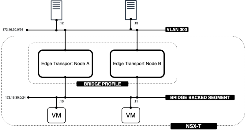
In this wiki article, I will show you how to configure Layer 2 Bridging between a VLAN (on the physical network) and a Segment (overlay network) on NSX-T with the same subnet. The goal is to not route network traffic through the Tier-0 and Tier-1 Gateways but to bridge network traffic using Layer 2 Logical bridging.
The Network Diagram
The goal of this article is to show you that the 172.16.30.12 IP address on VLAN 300 will be able to communicate with the 172.16.30.10 IP address on the NSX-T overlay using a Layer 2 Logical Bridge.
The high-level steps
In this wiki article, the high level following steps will be discussed:
This wiki article assumes that you have already created a multi-tier Logical Routing topology with a Tier-0 and Tier-1 Gateway running on two Edge Transport Nodes.
- STEP 1: Create vDS Bridge Port-Group (TRUNK)
- STEP 2: Create a new NSX-T Transport Zone (dedicated for the bridge interface)
- STEP 3: Add the new Transport Zone (Bridge) to the existing Edge Transport Nodes
- STEP 4: Create a Bridge Profile
- STEP 5: Configure a VLAN on the physical network with a gateway IP address
- STEP 6: Create test Virtual Machines on this VLAN to perform some ping tests
- STEP 7: Configure a Segment as an overlay network (on NSX-T) with a gateway IP address by attaching it to a Tier-1 Gateway
- STEP 8: Create test Virtual Machines on this Segment to perform some ping tests
- STEP 9: Configure the overlay network (Segment) as a Layer 2 Bridge-Backed Segment
- STEP 10: Perform some ping and traceroute tests between the VLAN and NSX-T Segment Virtual Machines
- STEP 11: Perform traceflow tests between the VLAN and NSX-T Segment Virtual Machines
- STEP 12: Looking at the bridge statistics
The configuration steps
STEP 1» Create vDS Bridge Port–Group 〈TRUNK〉
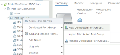
First, we need to create a VDS port group (on vSphere) that we will use for the Edge transport Node so that it can map one of the fast-path interfaces to this port group.
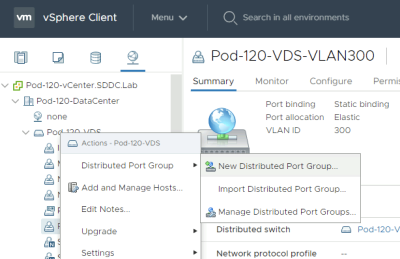
Go to the VDS and create a new port group.
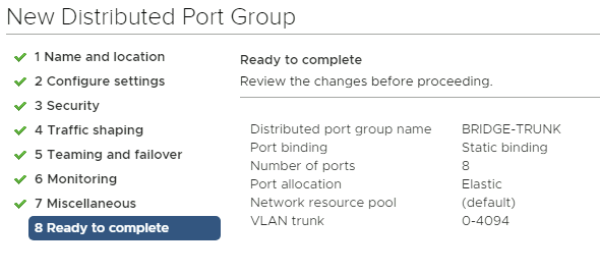
Give it a name. In my case, I named it "BRIDGE-TRUNK".
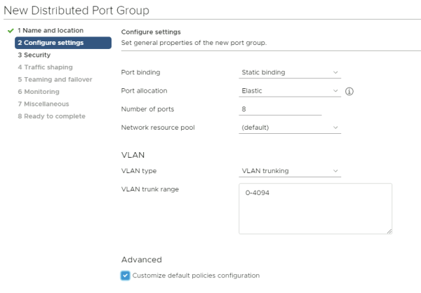
Make the VLAN Type a "VLAN Trunk" and allow all VLANs here. It is important that all the VLANs that you want to bridge are in this range.
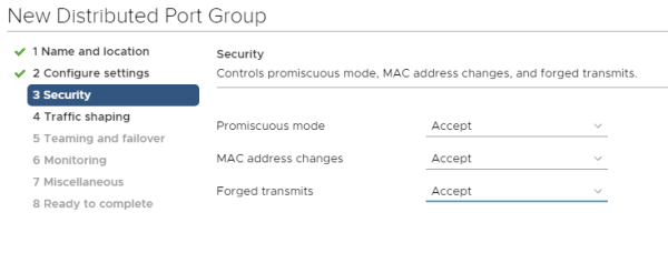
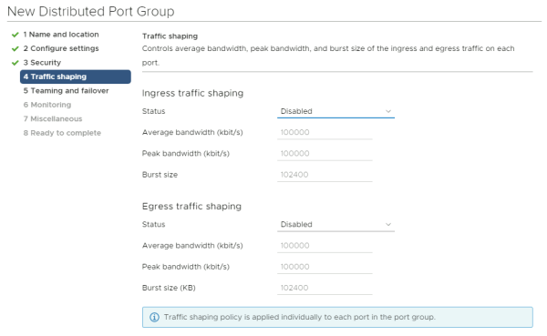
Make sure that all thee port group security settings are set to "Accept".
Do not change anything here.
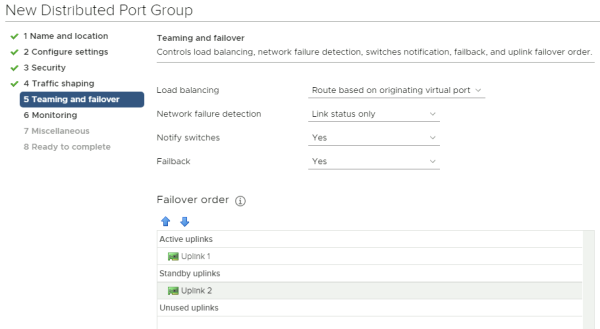
Now move the second uplink to the "standby uplinks" section and leave the first uplink in the "active uplinks" section.
Do not change anything here.
Do not change anything here.
Verify all your configuration settings and add the new port group.
STEP 2» Create a new NSX–T Transport Zone 〈dedicated for the bridge interface〉
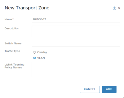
Add a new Transport Zone dedicated to bridging.
NSX-T GUI: System >> Configuration >> Fabric >> Transport Zones >> +Add
Add a new VLAN Transport Zone.
Verify if the new Transport Zone is added.
STEP 3» Add the new Transport Zone 〈Bridge〉 to the existing Edge Transport Nodes
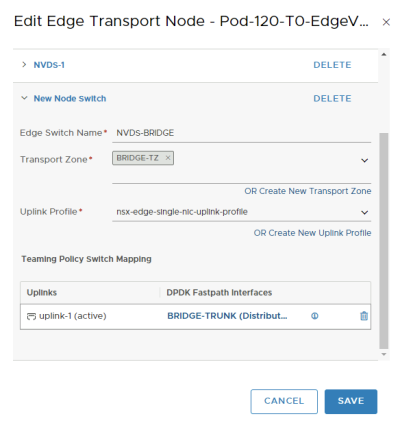
We now need to add an additional NVDS with that Transport Zone to the existing Edge Transport Nodes.
This is a list of my existing Edge Transport Nodes. Pay attention to the number of NVDSs (this is now 1)
Let's add the new NVDS and transport zone to the first Edge transport Node.
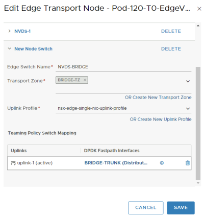
Let's add the new NVDS and transport zone to the second Edge transport Node.
Verify if the number of NVDSs has increased to 2.
STEP 4» Create a Bridge Profile
Now create a Bridge Profile.
NSX-T GUI: Networking >> Connectivity >> Segments >> Edge Bridge Profiles >> Add Edge Bridge Profile
STEP 5» Configure a VLAN on the physical network with a gateway IP address
I have used a virtual Vyatta Router that I have configured for networking. The configuration for the interfaces for Bridging is below.
configure

set interfaces ethernet eth1 vif 300 address '172.16.30.1/24'
set interfaces ethernet eth1 vif 300 description 'Bridge Test VLAN 300'
set interfaces ethernet eth1 vif 300 mtu '1500'

commit
save
vyos@Pod-120-Router:~$ show interfaces
Codes: S - State, L - Link, u - Up, D - Down, A - Admin Down
Interface        IP Address                        S/L  Description
----        ----------                        ---  -----------
<...>
eth1             -                                 u/u
eth1.300          172.16.30.1/24                   u/u  Bridge Test VLAN 300
<...>
vyos@Pod-120-Router:~$
STEP 6» Create test Virtual Machines on this VLAN to perform some ping tests
Create VLAN 300 Port Group
Now, we need to create a VDS port group (on vSphere) to simulate the "external" VLAN 300.
Go to the VDS and create a new port group.
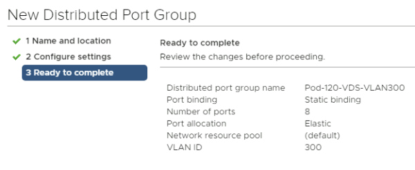
Give it a name. In my case, I named it "Pod-120-VDS-VLAN300".
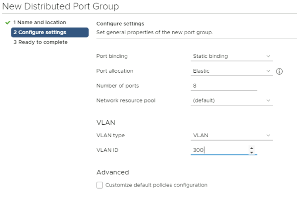
Make the VLAN Type a "VLAN" and type in VLAN 300 here.
Verify all your configuration settings and add the new port group.
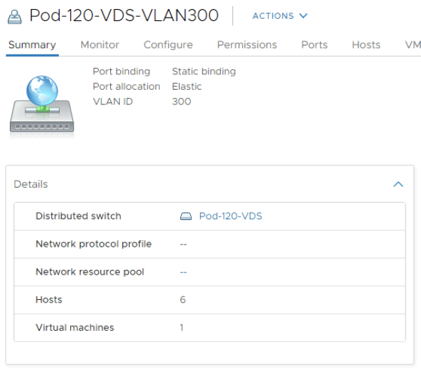
Verify if the VLAN port group with VLAN 300 is added
Create a Photon OS VM
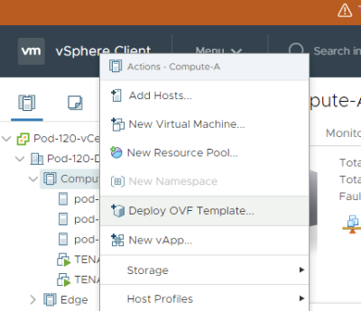
Deploy a new OVF Template from the Center Server Client.
Select the local Photon OS ova file.
Provide a name for your Virtual Machine.
Select a computing resource where you want to deploy the VM to.
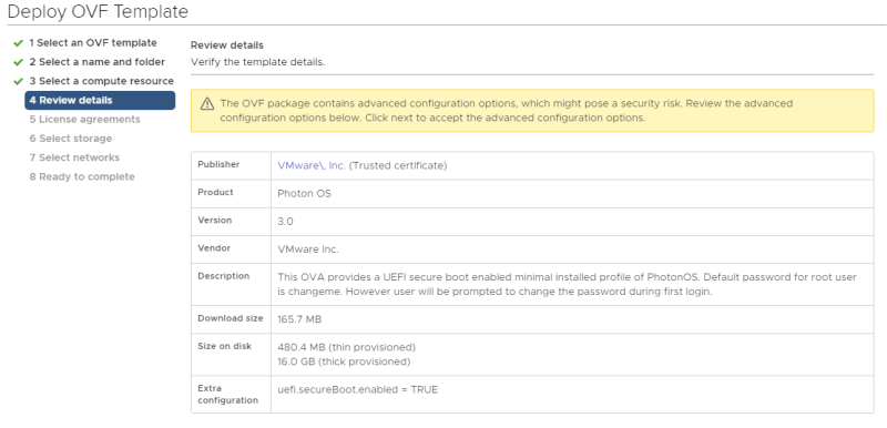
Review the details and just click next.
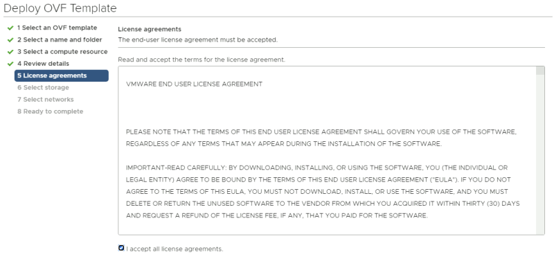
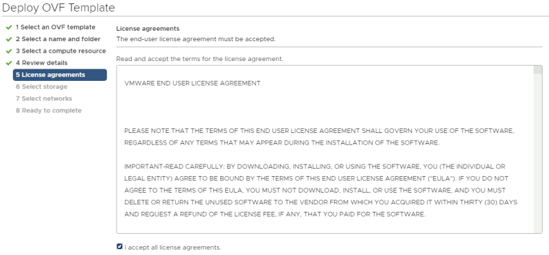
Accept the license agreement.
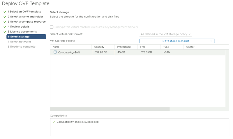
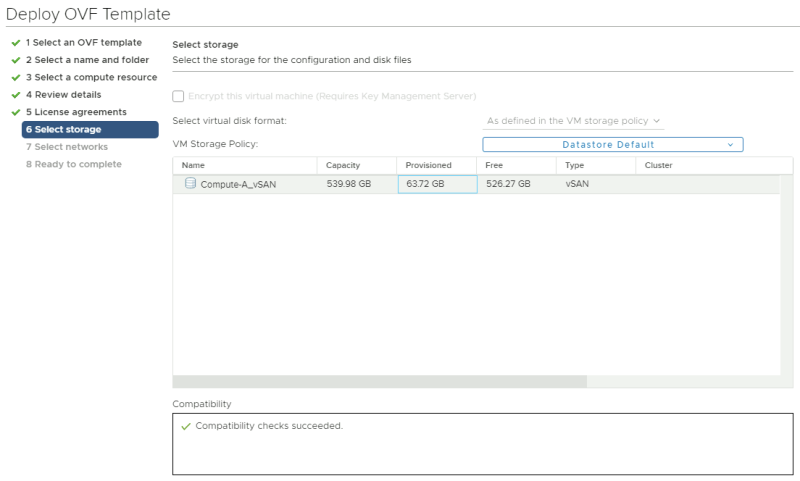
Select a storage resource where you want to deploy the VM to.
Select a networking resource that you want you're VM to be attached to. Make sure you select the VLAN 300 port group you created. Review the details before you finish (screenshot not shown).
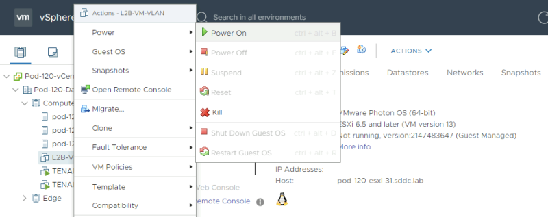
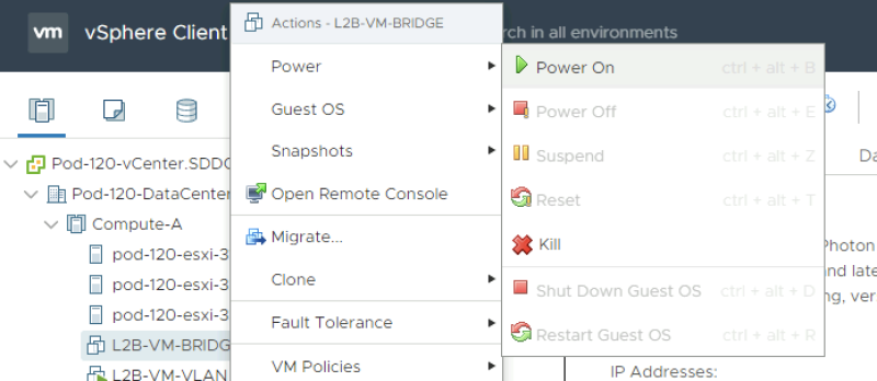
Power on the new Virtual Machine.
Network Configuration and Ping Tests
When the VM is ready and power on we need to log in to the console and provide network settings. the first time you log in to a newly deployed Photon OS VM you need to change the password. The default username is "root" and the default password is "changeme".
Welcome to Photon 3.0 (x86_64) - Kernel 4.19.79-1.ph3-esx (tty1)
photon-machine login: root
Password: changeme
You are required to change your password immediately (administrator enforced)
Changing password for root.
Current password: changeme
New password: VMware1!VMware1!
Retype new password: VMware1!VMware1!
Here we change the hostname.
root@photon-machine [ ~ ]# hostnamectl set-hostname l2b-vm-vlan
Here we create a network interface configuration file to specify the static IP address details for the network interface.
root@photon-machine [ ~ ]# vi /etc/systemd/network/10-static-en.network
This is the content of the "10-static-en.network" file.
[Match]
Name=eth0

[Network]
Address=172.16.30.12/24
Gateway=172.16.30.1
Here we change the rights to the file so the system is allowed to use it.
root@photon-machine [ ~ ]# chmod 644 /etc/systemd/network/10-static-en.network
Here we restart the networking service of the VM.
root@photon-machine [ ~ ]# systemctl restart systemd-networkd
Here we reboot the machine.
root@photon-machine [ ~ ]# reboot
When the machine is rebooted (with the new hostname) we can verify if the IP address is correct.
root@l2b-vm-vlan [ ~ ]# ip a
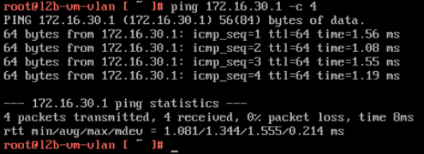
Here I do a quick ping towards my gateway to verify if we have network connectivity.
STEP 7» Configure a Segment as an overlay network 〈on NSX–T〉 with a gateway IP address by attaching it to a Tier–1 Gateway
Now we need to create a NSX-T Overlay segment that we are going to use to bridge VLAN 300 with.
NSX-T Manager GUI: Networking >> Connectivity >> Segments >> Add Segment
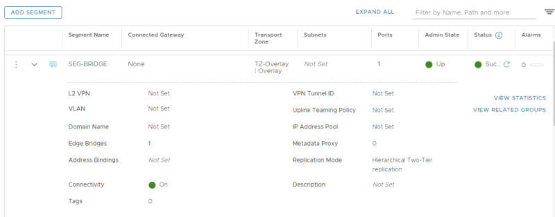
Verify if the Segment is correctly added.
STEP 8» Create test Virtual Machines on this Segment to perform some ping tests
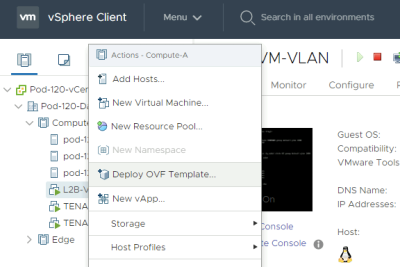
Deploy a new OVF Template from the Center Server Client.
Select the local Photon OS ova file.
Provide a name for your Virtual Machine.
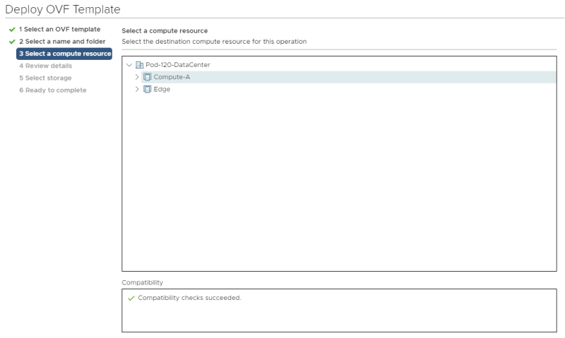
Select a computing resource where you want to deploy the VM to.
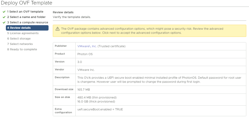
Review the details and just click next.
Accept the license agreement.
Select a storage resource where you want to deploy the VM to.
Select a networking resource that you want you're VM to be attached to. Make sure you select the NSX-T (Bridge) overlay Segment you created.
Review the details before you finish.
Power on the new Virtual Machine.
Network Configuration and Ping Tests
When the VM is ready and power on we need to log in to the console and provide network settings. the first time you log in to a newly deployed Photon OS VM you need to change the password. The default username is "root" and the default password is "changeme".
Welcome to Photon 3.0 (x86_64) - Kernel 4.19.79-1.ph3-esx (tty1)
photon-machine login: root
Password: changeme
You are required to change your password immediately (administrator enforced)
Changing password for root.
Current password: changeme
New password: VMware1!VMware1!
Retype new password: VMware1!VMware1!
Here we change the hostname.
root@photon-machine [ ~ ]# hostnamectl set-hostname l2b-test-vm-nsx
Here we create a network interface configuration file to specify the static IP address details for the network interface.
root@photon-machine [ ~ ]# vi /etc/systemd/network/10-static-en.network
This is the content of the "10-static-en.network" file.
[Match]
Name=eth0

[Network]
Address=172.16.30.10/24
Gateway=172.16.30.1
We configure a gateway here, but this gateway will reside on the VLAN side and NOT on the NSX-T side.
Here we change the rights to the file so the system is allowed to use it.
root@photon-machine [ ~ ]# chmod 644 /etc/systemd/network/10-static-en.network
Here we restart the networking service of the VM.
root@photon-machine [ ~ ]# systemctl restart systemd-networkd
Here we reboot the machine.
root@photon-machine [ ~ ]# reboot
When the machine is rebooted (with the new hostname) we can verify if the IP address is correct.
root@l2b-test-vm-nsx [ ~ ]# ip a
STEP 9» Configure the overlay network 〈Segment〉 as a Layer 2 Bridge–Backed Segment
Now I need to enable the bridging between the NSX-T overlay Segment and the VLAN. I do this inside the actual overlay segment we want to use for bridging.
NSX-T GUI: NSX-T Manager GUI: Networking >> Connectivity >> Segments >> SEG-BRIDGE >> EDIT
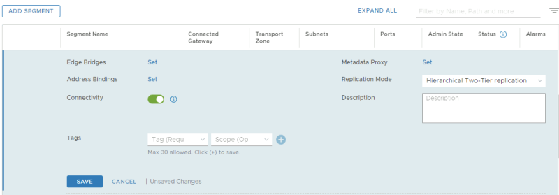
There is a label there called "Edge Bridges" click on "Set"
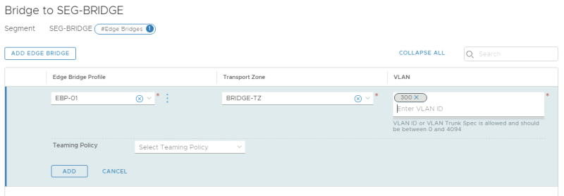
Select the Edge Bridge Profile and the Transport Zone that you created earlier. I have also added the VLAN 300 that I want to bridge to.
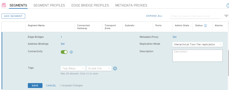
Verify if the Edge Bridge is added.
Verify if you see a little "1" in the Segment settings.
STEP 10» Perform some ping and traceroute tests between the VLAN and NSX–T Segment Virtual Machines
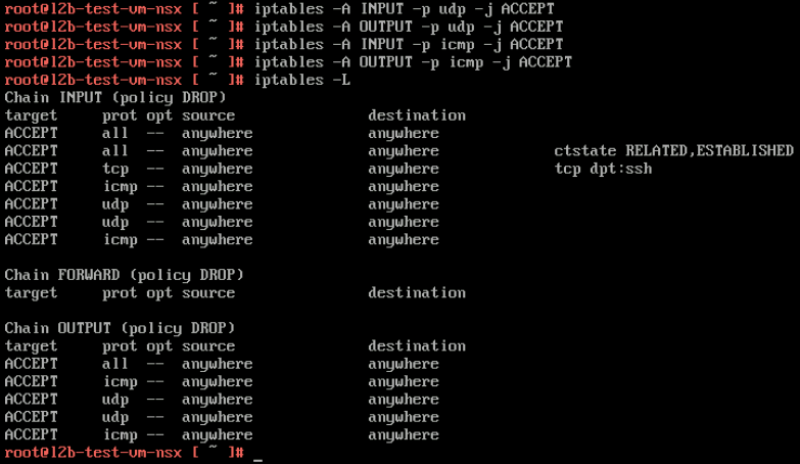
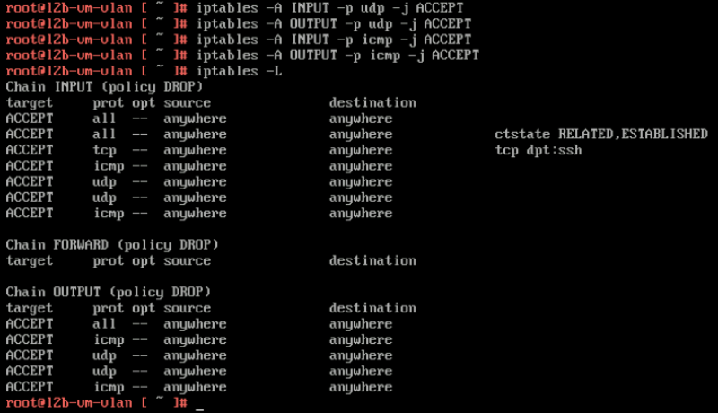
Because I am using Photon OS I first need to open up some INBOUND IPTABLE rules on the Tenant Virtual Machines to allow ping and traceroute/tracepath.
Open ICMP and UDP to allow ping and tracepath tests on the VLAN VM
Open ICMP and UDP to allow ping and tracepath tests on the OVERLAY VM
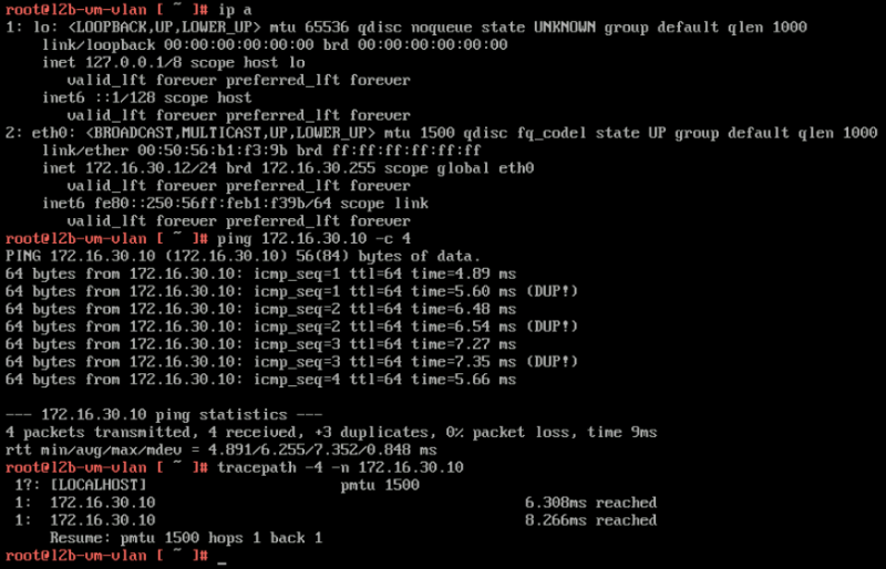
Tests from the VLAN VM to the OVERLAY VM
In the test below you can see that ping is working and that the tracepath is only showing one hop.
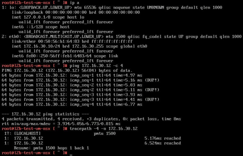
Tests from the OVERLAY VM to the VLAN VM
For the other way around you can see (below) that ping is working and that the tracepath is also only showing one hop.
STEP 11» Perform traceflow tests between the VLAN and NSX–T Segment Virtual Machines
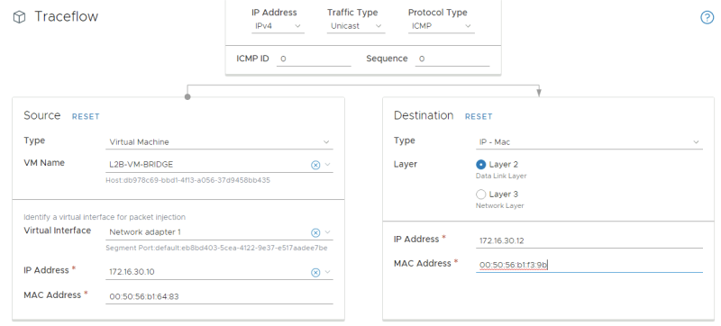
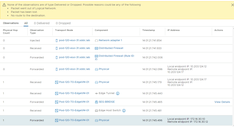
I also tried to use traceflow to see if I could retrieve some information from there.
But unfortunately, traceflow does not support bridged traffic flow tests.
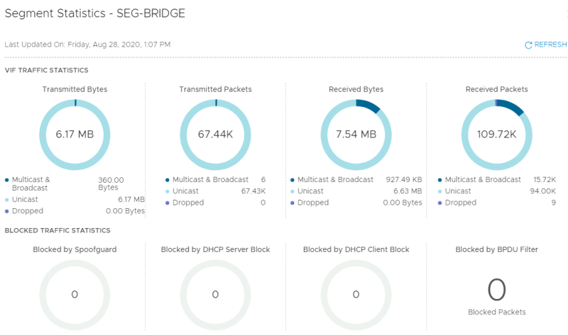
STEP 12» Looking at the bridge statistics
There is also a way to look at the bridge statistics under the segment.
Click on "view statistics".
Look at the statistics.
I am always trying to improve the quality of my articles so if you see any errors, mistakes in this article or you have suggestions for improvement, please contact me and I will fix this.
