Site to Site VPN with Static Routing between two OCI Regions using Libreswan as a CPE on one side and the DRG on the other side
When you have your applications, databases, or services spread into different OCI Regions (or even Tenants) and you need to allow network communication between the two OCI Regions the preferred method is the use of RPC Peering. If RPC peering is not the way you wait to use another option is to use a Site-to-Site IPSEC VPN connection. OCI does not support sending up a Site-to-Site IPSEC VPN connection using the DRG but you can set up a Site-to-Site IPSEC VPN connection using a custom VPN endpoint (like Libreswan) on one side and use the DRG on the other side.
This tutorial will explain how to set up a Site-to-Site VPN with Static Routing between two OCI Regions using Libreswan as a CPE on one side and the DRG on the other side.
You can also use this method if you need to set up a site-to-site VPN between ON-PREM and OCI and do not want to use the DRG as the VPN endpoint but your own custom VPN endpoint.
Prerequisites
Before you start you need to have two OCI Regions available:
OCI Region 1 (destination):
- VCN
- (Private) Subnet
- DRG
- VCN Attachments
- Instances
In this region the DRG will be the VPN endpoint and all traffic will be routed using the Internet connection of the DRG.
OCI Region 2 (source):
- VCN
- (Public) Subnet
- Internet Gateway
- Instances
In this region the Libreswan CPE (Instance inside OCI) will be the VPN endpoint and all traffic will be routed using the Internet connection of the Internet Gateway.
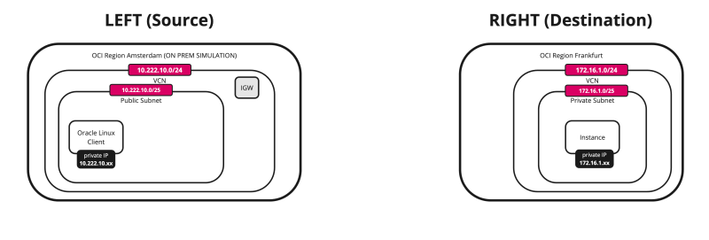
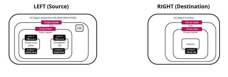
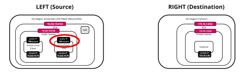
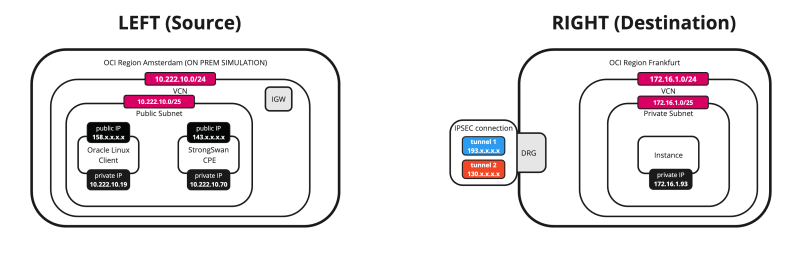
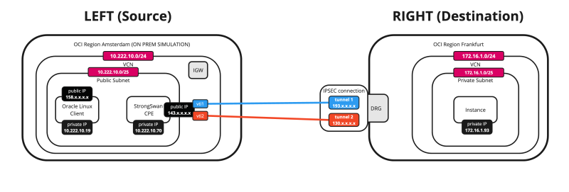
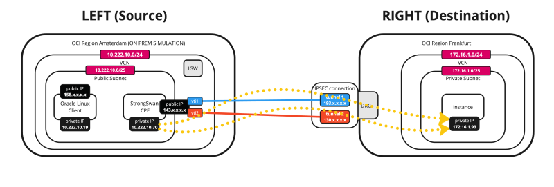
Below is a visual representation of what we have discussed so far. Note that the Libreswan CPE is NOT on this picture yet.
The Steps
- [ ] STEP 01: Review the Destination OCI Region (right) VCN, Subnet, DRG, and Instances
- [ ] STEP 02: Review the Source OCI Region (left) VCN, Public Subnet, Internet Gateway, and Instances
- [ ] STEP 03: Collect the public IP address of the CPE Instance in the Source OCI Region (left)
- [ ] STEP 04: Create a new CPE in the Destination OCI Region (right)
- [ ] STEP 05: Configure the Site-to-Site VPN in the Destination OCI Region (right)
- [ ] STEP 06: Collect the public IP address of the IPsec Tunnels in the Destination OCI Region (right) and download the CPE configuration
- [ ] STEP 07: Configure the CPE Instance in the Source OCI Region (left) and install and configure Libreswan
- [ ] STEP 08: Open the firewall on the CPE Instance in the Source OCI Region and configure the VCN/Subnet Security Lists to allow the ingress ports required for the IPSec connection
- [ ] STEP 09: Activate and verify if the IPSec tunnel is up on both sides
- [ ] STEP 10: Configure Static Routing
- [ ] STEP 11: Do one final ping initiated from the source and destination Instances
- [ ] STEP 12: Look at the OCI dashboards to verify the Site-to-site VPN status
- [ ] STEP 13: Enable ECMP Routing
STEP 01 - Review the Destination OCI Region -right- VCN, Subnet, DRG, VCN Attachments and Instances
Creating the prerequisites is out of the scope of this tutorial; however, I will show you what we have in place to get started.
VCN
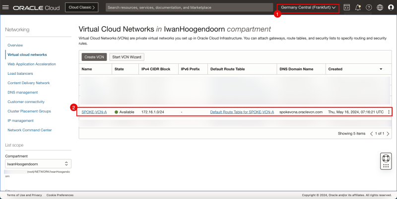
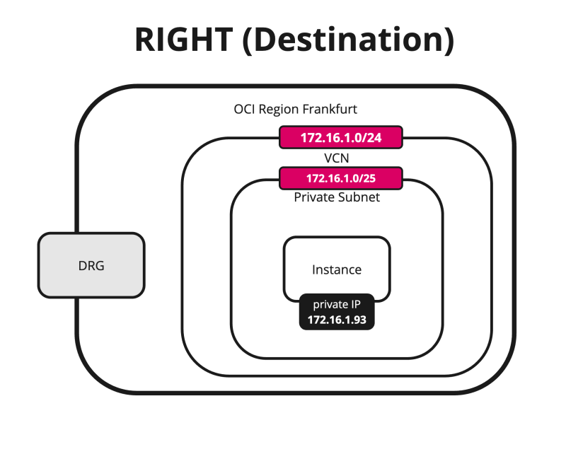
- Review the destination OCI Region (in my case I used the Germany Central (Frankfurt) OCI region).
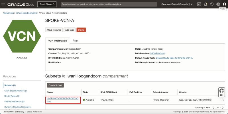
- Review the VCN, where my subnets and Instances will be.
Subnets
- Review the private Subnet to where my Instances will be attached to.
DRG
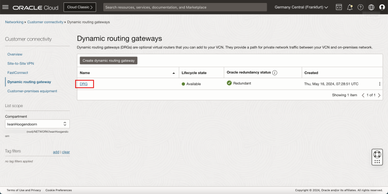
- Review the DRG that will be used as a VPN endpoint to terminate the VPN.
VCN Attachment
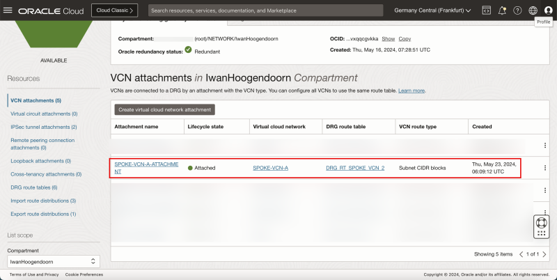
- Review the VCN Attachment, to make sure the VCN is attached to the DRG so that the DRG can route VPN traffic to the correct VCN, Subnet, and Instance.
Instance
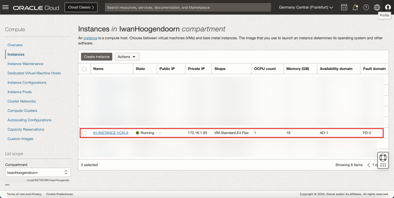
- Review the Instance that we will use as a network endpoint to perform our network tests.
Below is a visual representation of what we have discussed so far.
STEP 02 - Review the Source OCI Region -left- VCN, Public Subnet, Internet Gateway, and Instances
VCN
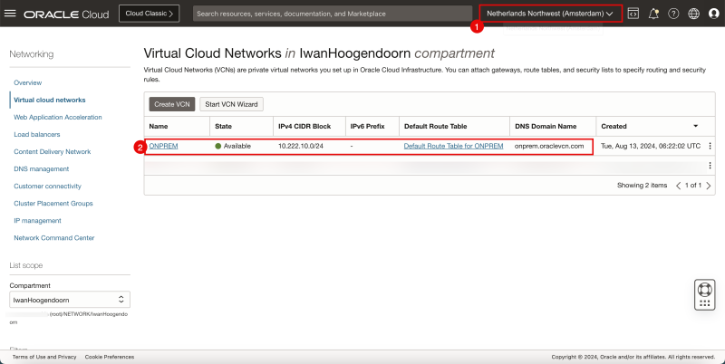
- Review the source OCI Region (in my case I used the Netherlands Northwest (Amsterdam) OCI region).
- Review the VCN, where my subnets and Instances will be in.
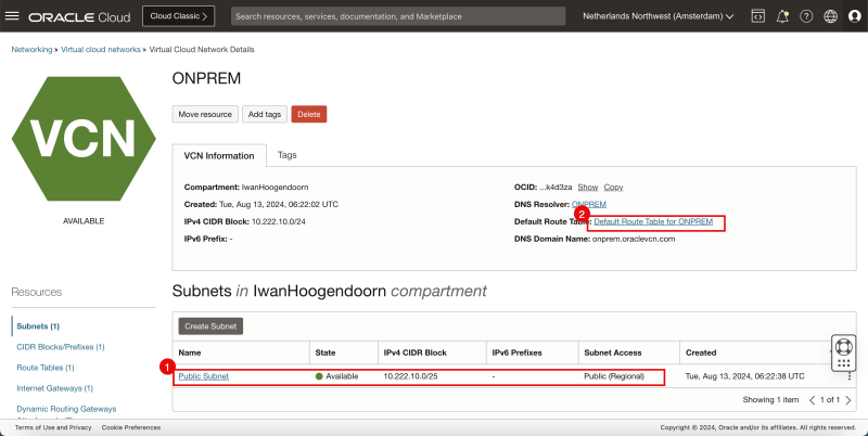
Public Subnet
- Review the public Subnet to which my Instances and the Libreswan VPN endpoint will be attached.
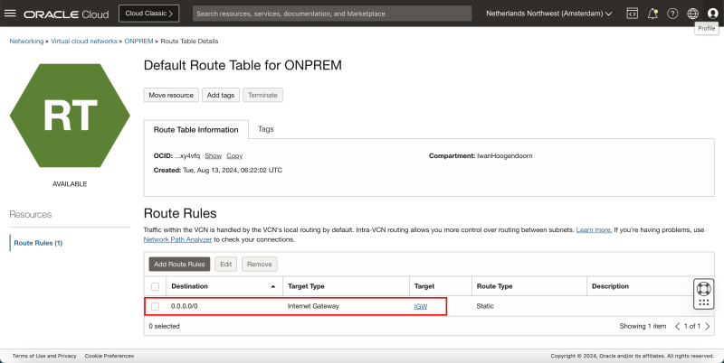
- Review the default route table for the VCN.
- We need to have a public subnet here, as we need to make sure that the Libreswan VPN endpoint can communicate to the internet to set up the VPN connection with the other side.
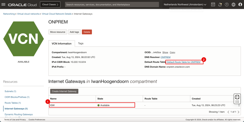
Internet Gateway
- Review the Internet Gateway (to allow internet connectivity)
- Review the default route table for the VCN.
Route Table
- Review the VCN route table, and make sure all traffic is routed to the internet gateway.
Instances
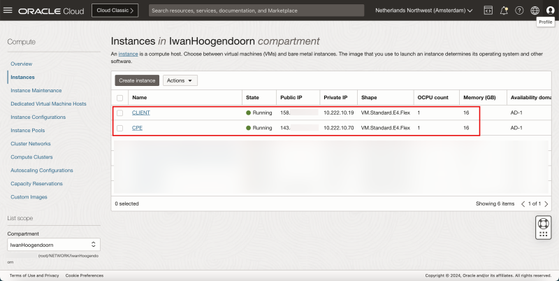
- Review the Instance that we will use as a network endpoint to perform our network tests.
- For both CLIENT and CPE I have used Oracle Linux 8 as the main OS.
Below is a visual representation of what we have discussed so far.
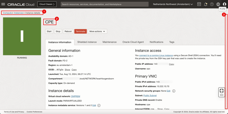
STEP 03 - Collect the public IP address of the CPE Instance in the Source OCI Region -left-
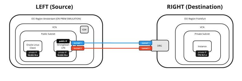
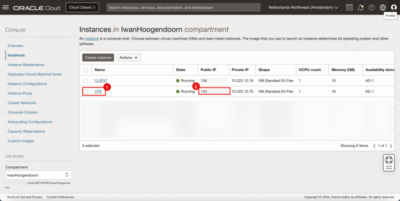
- In the source OCI Region we deploy an Instance that will be responsible for the VPN termination (VPN endpoint)
- Collect the public IP address that is configured on this VPN endpoint. In my case, this public IP address starts with 143.
Below is a visual representation of what we have discussed so far.
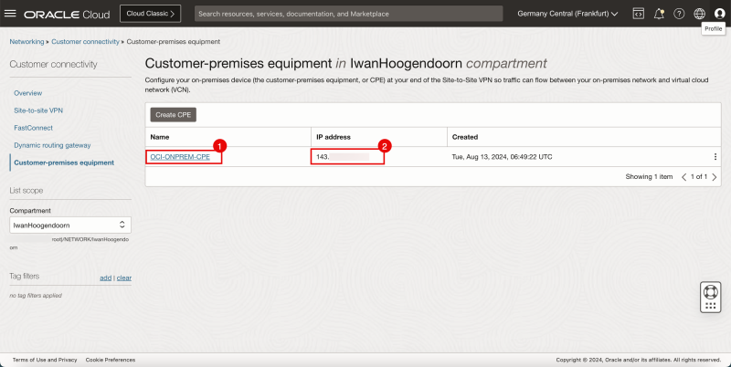
STEP 04 - Create a new CPE in the Destination OCI Region -right-
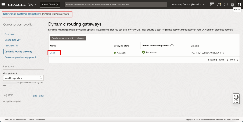
- Browse to the DRG on the OCI Console by going through Networking > Customer Connectivity > Dynamic routing gateway.
- Click on the DRG.
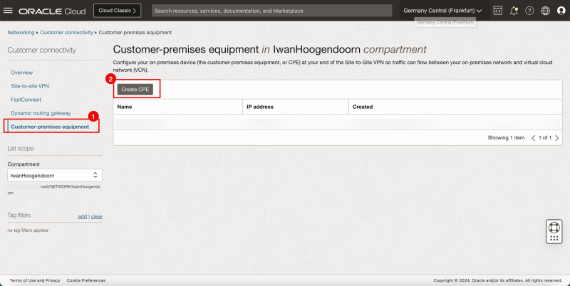
- Click on Customer premises equipment.
- Click on the Create CPE button.
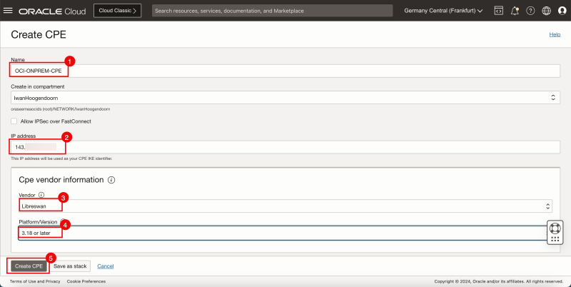
- Specify a name for the CPE.
- Specify the public IP address that you have collected in the step before (of the CPE).
- Select the CPE Vendor to be Libreswan.
- Select the CPE Platform version.
- Click on the Create CPE button.
- Notice that the CPE is now created.
- Notice the Public IP address of the CPE.
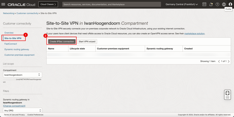
STEP 05 - Configure the Site-to-Site VPN in the Destination OCI Region -right-
- Click on Site-to-Site VPN.
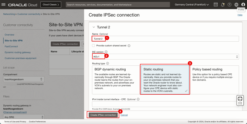
- Click on the Create IPSec connection button.
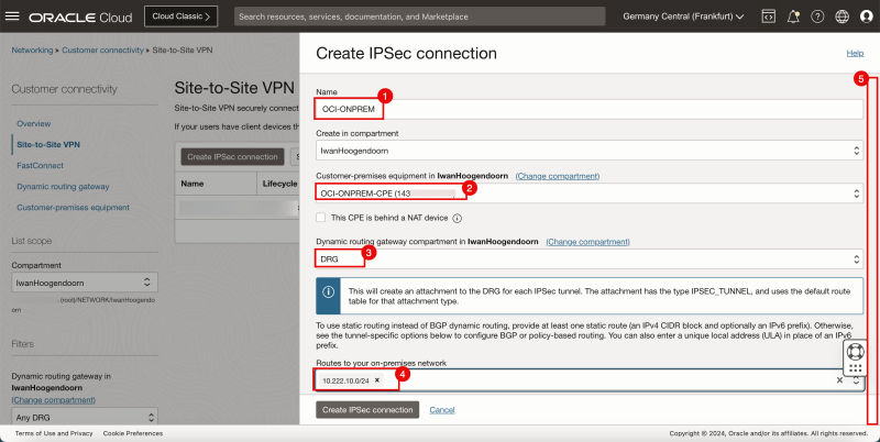
- Specify a name for the IPSec connection.
- Select the CPE you just created.
- Select the DRG.
- Specify the REMOTE network (left side) that you want to route through the IPSec connection. In my case, this is the 10.222.10.0/24 network.
- Scroll down.
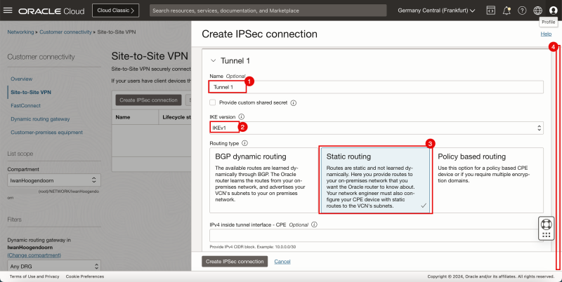
- Specify the name for the first tunnel.
- Specify the IKE version to be IKEv1.
- Select Static Routing.
- Scroll down.
- Specify the name for the second tunnel.
- Specify the IKE version to be IKEv1.
- Select Static Routing.
- Click on the Create IPSec connection button.
STEP 06 - Collect the public IP address of the IPsec Tunnels in the Destination OCI Region -right- and download the CPE configuration
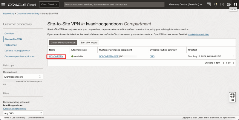
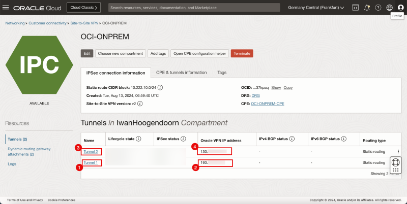
- Now that the IPSec connection is created the public IP addresses for both IPSec tunnels will be available and we will need to configure the other side of the VPN.
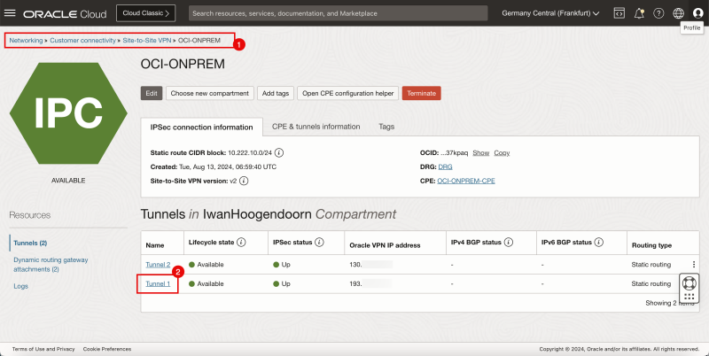
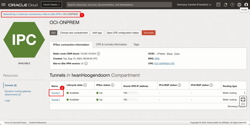
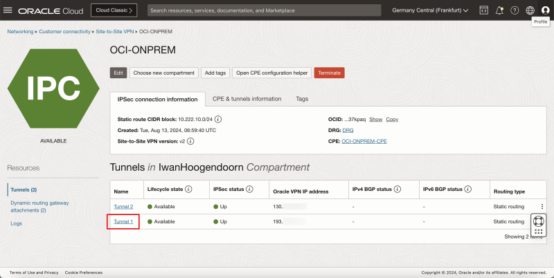
- Click on the Site-to-Site VPN we just created.
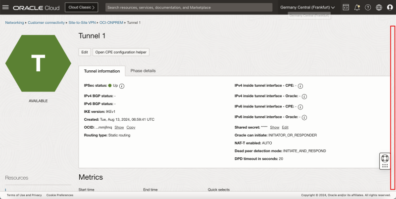
- Notice tunnel 1 of the IPSec connection.
- Note down the public IP address for tunnel # In my case, this IP address starts with 193.
- Notice tunnel 2 of the IPSec connection.
- Note down the public IP address for tunnel # In my case, this IP address starts with 130.
Below is a visual representation of what we have discussed so far.
STEP 07 - Configure the CPE Instance in the Source OCI Region -left- and install and configure Libreswan
- Set up an SSH session for the CPE located in the source OCI Region / VCN.
- Make sure you are logged in.
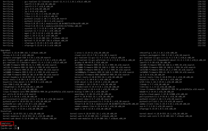
- Issue the following command to upgrade the software.
[opc@cpe ~]$ sudo dnf upgrade -y
- Make sure the upgrade is successfully upgraded.
- Issue the following command so you can execute the command where higher privileges are required.
[opc@cpe ~] sudo su
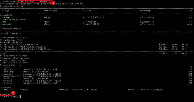
- Issue the following command to install the Libreswan software.
- Notice that the software is successfully installed.
[root@cpe opc]# sudo yum install libreswan -y
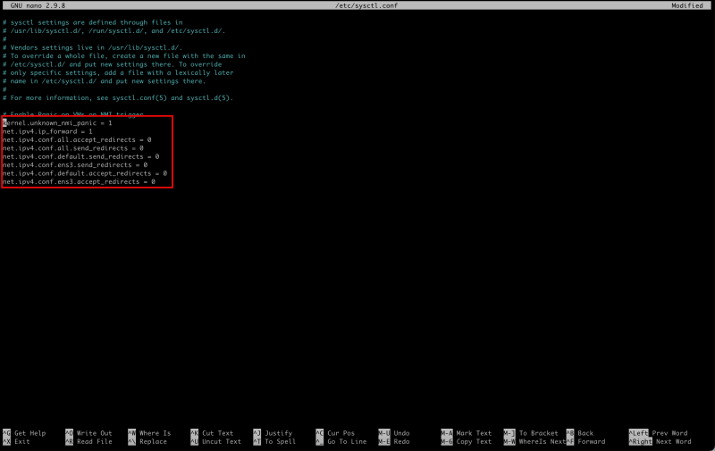
- Edit the following file to enable IP Forwarding.
[root@cpe etc]# nano /etc/sysctl.conf
- Make sure the `/etc/sysctl.conf` file contains the following content.
kernel.unknown_nmi_panic = 1
net.ipv4.ip_forward = 1
net.ipv4.conf.all.accept_redirects = 0
net.ipv4.conf.all.send_redirects = 0
net.ipv4.conf.default.send_redirects = 0
net.ipv4.conf.ens3.send_redirects = 0
net.ipv4.conf.default.accept_redirects = 0
net.ipv4.conf.ens3.accept_redirects = 0
- Make sure you save the file with `CNTRL + X` and type `“Y”`.
- Issue the following command to verify the file's content.
- Notice the output will be the same as the content of the file.
[root@cpe opc]# more /etc/sysctl.conf
- Issue the following command to reload/apply the file (to enable forwarding).
[root@cpe etc]# sudo sysctl -p
- Issue the following command to verify if IP forwarding is enabled
- Notice that the returned value id `"1"` and this means that IP forwarding is enabled. A `"0"` means that IP forwarding is disabled.
cat /proc/sys/net/ipv4/ip_forward
- Issue the following command to change the directory where you need to configure the IPSEC tunnels.
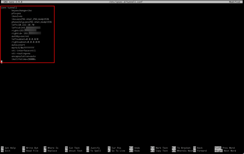
- Create/Edit the following file to configure the first IPSEC tunnel (tunnel1).
[root@cpe opc]# cd /etc/ipsec.d/
[root@cpe ipsec.d]# nano /etc/ipsec.d/tunnel1.conf
- Make sure the `/etc/ipsec.d/tunnel1.conf` file contains the following content.
conn tunnel1
    keyexchange=ike
    pfs=yes
    ikev2=no
    ike=aes256-sha2_256;modp1536
    phase2alg=aes256-sha1;modp1536
    left=10.222.10.70
    leftid=143.xxx.xxx.xxx
    right=193.xxx.xxx.xxx
    rightid= 193.xxx.xxx.xxx
    authby=secret
    leftsubnet=0.0.0.0/0
    rightsubnet=0.0.0.0/0
    auto=start
    mark=5/0xffffffff
    vti-interface=vti1
    vti-routing=no
    encapsulation=auto
    ikelifetime=28800s
- Make sure you save the file with `CNTRL + X` and type `“Y”`.
- Create/Edit the following file to configure the second IPSEC tunnel (tunnel2).
[root@cpe ipsec.d]# nano /etc/ipsec.d/tunnel2.conf
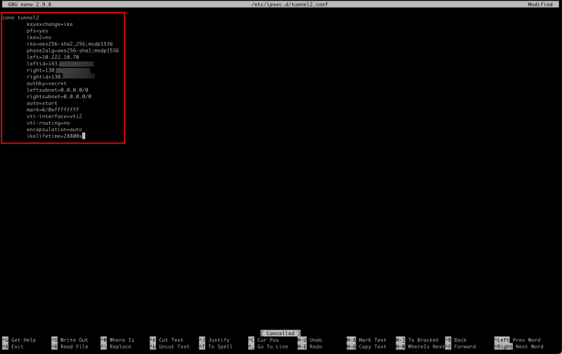
- Make sure the `/etc/ipsec.d/tunnel2.conf` file contains the following content.
conn tunnel2
    keyexchange=ike
    pfs=yes
    ikev2=no
    ike=aes256-sha2_256;modp1536
    phase2alg=aes256-sha1;modp1536
    left=10.222.10.70
    leftid=143.xxx.xxx.xxx
    right=130.xxx.xxx.xxx
    rightid=130.xxx.xxx.xxx
    authby=secret
    leftsubnet=0.0.0.0/0
    rightsubnet=0.0.0.0/0
    auto=start
    mark=6/0xffffffff
    vti-interface=vti2
    vti-routing=no
    encapsulation=auto
    ikelifetime=28800s
- Make sure you save the file with `CNTRL + X` and type `“Y”`.
- Issue the following command to verify the file's content for tunnel1.
- Notice the output will be the same as the content of the file.
- Issue the following command to verify the file's content for tunnel2.
- Notice the output will be the same as the content of the file.
[root@cpe ipsec.d]# more /etc/ipsec.d/tunnel1.conf
[root@cpe ipsec.d]# more /etc/ipsec.d/tunnel2.conf
Now that we have configured the IPSEC tunnels we also need to configure the shared secrets as we are using a secret (key) for authentication.
When we created the Site-to-Site VPN in Step 5, the tunnels were created and in this process, OCI also generated the shared secret keys per tunnel. To get them and configure them in Libreswan to match the same shared secret, we need to go back to the OCI console.
- Browse to the Site-to-Site settings on the OCI Console by going through Networking > Customer Connectivity > Site-to-Site VPN > The configured VPN.
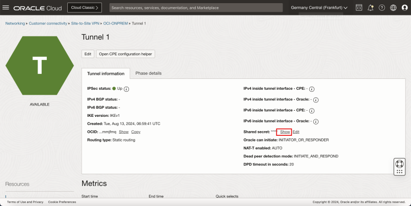
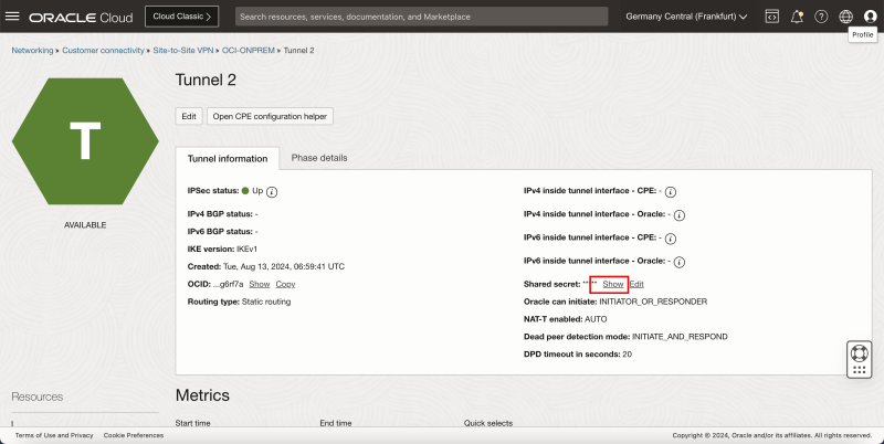
- Click on the first tunnel configuration.
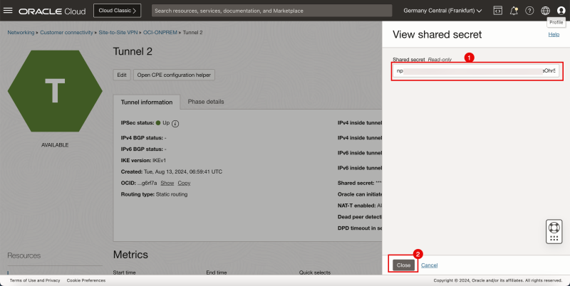
- For the shared secret click on show.
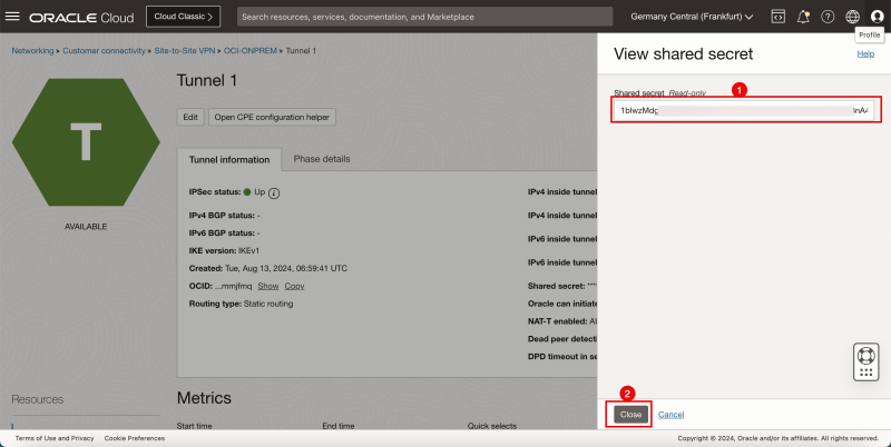
- Copy the shared secret for tunnel 1 and save it on a notepad so you can access it quickly later.
- Click on the Close button.
- Browse to the Site-to-Site settings on the OCI Console by going through Networking > Customer Connectivity > Site-to-Site VPN > The configured VPN.
- Click on the second tunnel configuration.
- For the shared secret click on show.
- Copy the shared secret for tunnel 2 and save it on a notepad so you can access it quickly later.
- Click on the Close button.
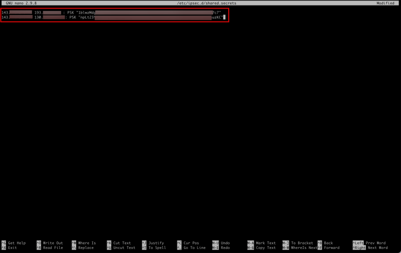
- Now that you have collected the shared secrets you need to configure them on Libreswan.
- Create/Edit the following file to configure the shared secrets for both tunnels.
[root@cpe ipsec.d]# nano /etc/ipsec.d/shared.secrets
- Make sure the `/etc/ipsec.d/shared.secrets` file contains the following content.
143.xxx.xxx.xxx 193.xxx.xxx.xxx : PSK "1blwzMdgQ5XXXoiQwF96tqc7c7"
143.xxx.xxx.xxx 130.xxx.xxx.xxx : PSK "npLt23Ym6E1XXXhr5egvYSuzKC"
- Issue the following command to verify the file's content.
- Notice the output will be the same as the content of the file.
[root@cpe ipsec.d]# more /etc/ipsec.d/shared.secrets
- Issue the following command to start the IPSEC Service on the Libreswan.
- This will NOT establish the tunnels yet.
[root@cpe ipsec.d]# ipsec start
- Issue this command to verify the status of the IPsec connections.
- Notice that the verification looks ok, without any strange errors.
[root@cpe ipsec.d]# ipsec verify
STEP 08 - Open the firewall on the CPE Instance in the Source OCI Region -left- and configure the VCN and Subnet Security Lists to allow the ingress ports required for the IPSec connection
To allow the tunnels to be established correctly, you need to make sure the network security on both sides is allowing the ports that are required.
First, we start on the source OCI Region that hosts the Libreswan CPE.
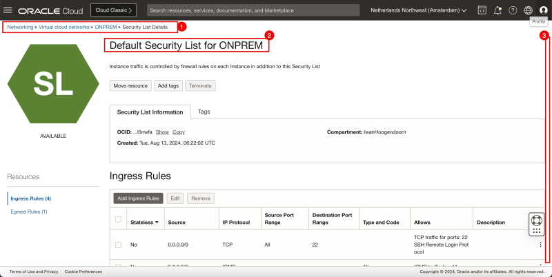
- Browse to the Security List settings on the OCI Console by going through Networking > Virtual cloud networks > Select the VCN > Security Lists.
- Make sure you select the Default Security List.
- Scroll down.
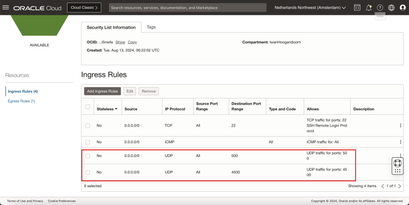
- Make sure you have added the following Ingress Security Rules:
| Source | IP Protocol | Source Port | Destination Port |
|---|---|---|---|
| 0.0.0.0/0 | UDP | All | 500 |
| 0.0.0.0/0 | UDP | All | 4500 |
- On the Libreswan CPE itself, you also need to open the firewall ports.
- Issue this command to review the existing configured firewall rules.
- Notice that there are no rules configured related to the IPSEC ports.
- Issue this command to allow UDP port 500 on the CPE.
- Issue this command to allow UDP port 4500 on the CPE.
- Issue this command to make the firewall rules permanent (so they will remain after a reboot)
- Issue this command to review the existing configured firewall rules
- Notice that there are no rules configured related to the IPSEC ports.
[root@cpe ipsec.d]# sudo firewall-cmd --list-all
[root@cpe ipsec.d]# sudo firewall-cmd --add-port=500/udp
[root@cpe ipsec.d]# sudo firewall-cmd --add-port=4500/udp
[root@cpe ipsec.d]# sudo firewall-cmd --runtime-to-permanent
[root@cpe ipsec.d]# sudo firewall-cmd --list-all
- Issue this command to make sure the firewall service of the Libreswan is running.
- Notice that the firewall service is active and running.
[root@cpe ipsec.d]# systemctl status firewalld
- Issue this command to restart the IPSEC service.
[root@cpe ipsec.d]# service ipsec restart
Disable the Linux Firewall on the CPE
In some cases (for testing purposes) it might be better to completely disable the Linux Firewall of the CPE Instance where Libreswan is running on. This can be done with the following command:
[root@cpe ipsec.d]# systemctl disable --now firewalld
Run the following command to make sure the firewall service for Libreswan is NOT running.
[root@cpe ipsec.d]# systemctl status firewalld
STEP 09 - Activate and verify if the IPSec tunnel is up on both sides
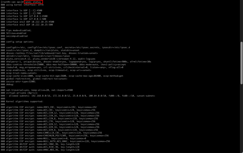
- Issue the following command to verify the IPSEC status for both tunnels.
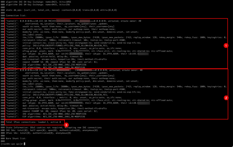
[root@cpe ipsec.d]# ipsec status
- Notice the configuration and status for the first IPSEC tunnel.
- Notice the configuration and status for the second IPSEC tunnel.
- Notice that the number of IPSEC loaded is 2, and the active number is 0.
- Issue the following command to add tunnel1.
[root@cpe ipsec.d]# ipsec auto --add tunnel1
- Notice the output given by the terminal when tunnel1 is added.
002 "tunnel1": terminating SAs using this connection
002 "tunnel1" #3: deleting state (STATE_QUICK_I2) aged 3.504567s and sending notification
005 "tunnel1" #3: ESP traffic information: in=0B out=0B
002 "tunnel1" #1: deleting state (STATE_MAIN_I4) aged 3.541172s and sending notification
002 "tunnel1": added IKEv1 connection
- Issue the following command to bring tunnel1 up.
[root@cpe ipsec.d]# ipsec auto --up tunnel1
- Notice the output given by the terminal when tunnel1 is brought up.
002 "tunnel1" #5: initiating IKEv1 Main Mode connection
102 "tunnel1" #5: sent Main Mode request
104 "tunnel1" #5: sent Main Mode I2
106 "tunnel1" #5: sent Main Mode I3
002 "tunnel1" #5: Peer ID is ID_IPV4_ADDR: '193.122.0.91'
004 "tunnel1" #5: IKE SA established {auth=PRESHARED_KEY cipher=AES_CBC_256 integ=HMAC_SHA2_256 group=MODP1536}
002 "tunnel1" #6: initiating Quick Mode IKEv1+PSK+ENCRYPT+TUNNEL+PFS+UP+IKE_FRAG_ALLOW+ESN_NO+ESN_YES {using isakmp#5 msgid:b6364de1 proposal=AES_CBC_256-HMAC_SHA1_96-MODP1536 pfsgroup=MODP1536}
115 "tunnel1" #6: sent Quick Mode request
002 "tunnel1" #6: up-client output: vti interface "vti1" already exists with conflicting setting (perhaps need vti-sharing=yes ?
002 "tunnel1" #6: prepare-client output: vti interface "vti1" already exists with conflicting setting (perhaps need vti-sharing=yes ?
004 "tunnel1" #6: IPsec SA established tunnel mode {ESPinUDP=>0x5036cdcc <0x33c964f9 xfrm=AES_CBC_256-HMAC_SHA1_96 NATD=193.122.0.91:4500 DPD=passive}
- Issue the following command to add tunnel2.
[root@cpe ipsec.d]# ipsec auto --add tunnel2
- Notice the output given by the terminal when tunnel2 is added.
002 "tunnel2": terminating SAs using this connection
002 "tunnel2" #4: deleting state (STATE_QUICK_I2) aged 25.694856s and sending notification
005 "tunnel2" #4: ESP traffic information: in=0B out=0B
002 "tunnel2" #2: deleting state (STATE_MAIN_I4) aged 25.731704s and sending notification
002 "tunnel2": added IKEv1 connection
- Issue the following command to bring tunnel2 up.
[root@cpe ipsec.d]# ipsec auto --up tunnel2
- Notice the output given by the terminal when tunnel2 is brought up.
002 "tunnel2" #7: initiating IKEv1 Main Mode connection
102 "tunnel2" #7: sent Main Mode request
104 "tunnel2" #7: sent Main Mode I2
106 "tunnel2" #7: sent Main Mode I3
002 "tunnel2" #7: Peer ID is ID_IPV4_ADDR: '130.61.66.255'
004 "tunnel2" #7: IKE SA established {auth=PRESHARED_KEY cipher=AES_CBC_256 integ=HMAC_SHA2_256 group=MODP1536}
002 "tunnel2" #8: initiating Quick Mode IKEv1+PSK+ENCRYPT+TUNNEL+PFS+UP+IKE_FRAG_ALLOW+ESN_NO+ESN_YES {using isakmp#7 msgid:aeb4eb18 proposal=AES_CBC_256-HMAC_SHA1_96-MODP1536 pfsgroup=MODP1536}
115 "tunnel2" #8: sent Quick Mode request
002 "tunnel2" #8: up-client output: vti interface "vti2" already exists with conflicting setting (perhaps need vti-sharing=yes ?
002 "tunnel2" #8: prepare-client output: vti interface "vti2" already exists with conflicting setting (perhaps need vti-sharing=yes ?
004 "tunnel2" #8: IPsec SA established tunnel mode {ESPinUDP=>0x8bef7076 <0xe27d84a0 xfrm=AES_CBC_256-HMAC_SHA1_96 NATD=130.61.66.255:4500 DPD=passive}
[root@cpe ipsec.d]#
- Issue the following command again to verify the IPSEC status for both tunnels.
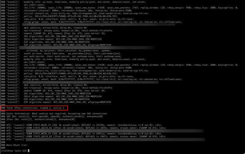
[root@cpe ipsec.d]# ipsec status
- Notice that the active tunnels have gone from 0 to 2.
- Let's move back to the destination side on the OCI console.
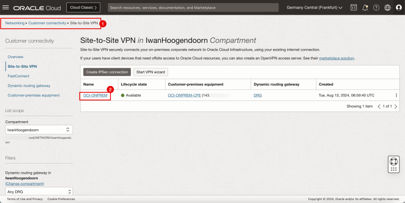
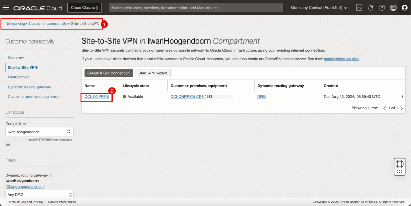
- Browse to the Site-to-Site settings on the OCI Console by going through Networking > Customer Connectivity > Site-to-Site VPN.
- Click on the VPN connection.
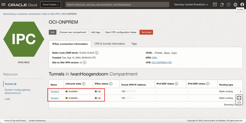
- Notice that Tunnel 1 and Tunnel 2 are both Available and Up.
Below is a visual representation of what we have discussed so far.
STEP 10 - Configure Static Routing
- Now that the tunnels are up we need to make sure the required traffic is routed through the tunnel.
- Issue the following command to review the configured (tunnel) interfaces.
- Notice vti1 that is responsible for tunnel1.
- Notice vti2 that is responsible for tunnel2.
[root@cpe ipsec.d]# ifconfig
- Issue the following command to route the `172.16.0.0/16` network through the `vti1` and `vti2` interfaces.
[root@cpe ipsec.d]# ip route add 172.16.0.0/16 nexthop dev vti1 weight 1 nexthop dev vti2 weight 1
- Issue the following command to review if the route is added.
- Notice that the routes are added.
[root@cpe ipsec.d]# ip route
STEP 11 - Do one final ping initiated from the source and destination Instances
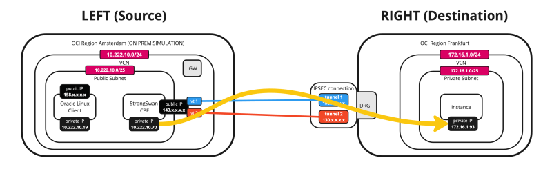
- Issue the following command from the SOURCE (CPE) to verify if the ping is working from the Source OCI Region to the Destination OCI Region.
- Notice that we have 0% packet loss.
[root@cpe ipsec.d]# ping 172.16.1.93 -c 4
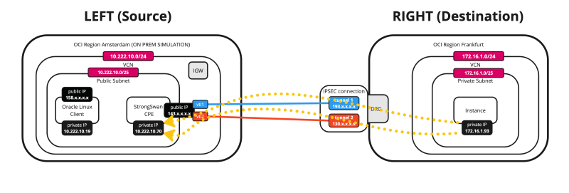
Below is a visual representation of what we have discussed so far.
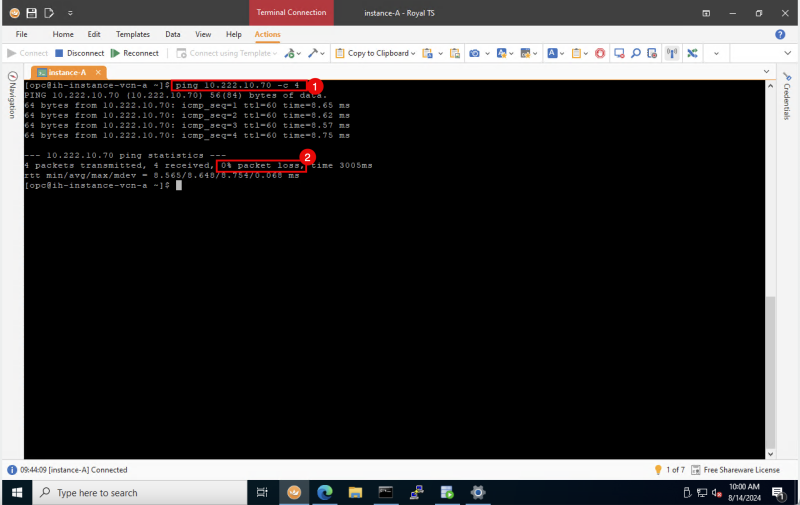
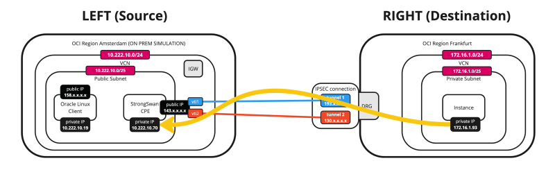
- Issue the following command from the DESTINATION to verify if the ping is working from the Destination OCI Region to the Source OCI Region (CPE).
- Notice that we have 0% packet loss.
[opc@ih-instance-vcn-a ~]$ ping 10.222.10.70 -c 4
Below is a visual representation of what we have discussed so far.
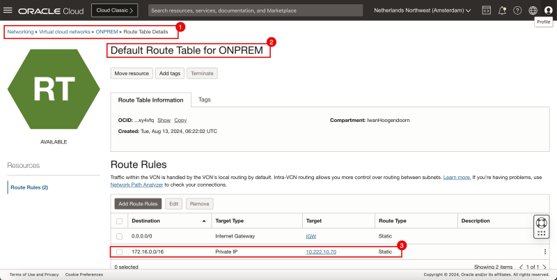
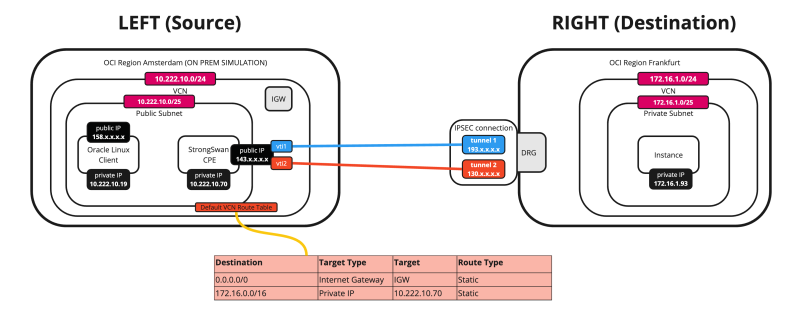
If you want to route all the traffic from the other instances (in the same subnet) on the source OCI Region through the tunnels, you need to add a static route on the VCN Route table. This route routes all traffic destined for`172.16.0.0/24` to the CPE (`10.222.10.70`).
Below is a visual representation of what we have discussed so far (with the full route table).
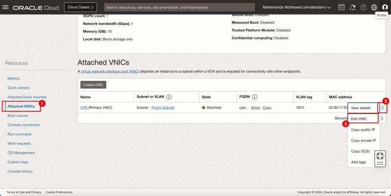
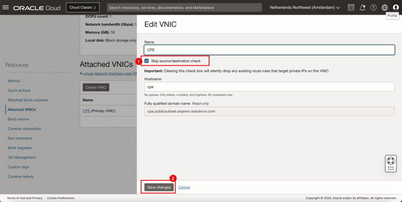
Before you can add a route towards a Private IP address (Libreswan CPE) you first need to enable the Skip Source/Destination check on the Instance (Libreswan CPE) VNIC.
- Browse to Compute > Instances.
- Select the CPE.
- Scroll down.
- Click on Attached VNICs.
- Click on the three dots.
- Click on Edit VNIC.
- Check the box Skip source/destination check.
- Click on the Save changes button.
Now let's add the route.
- Browse to Networking > Virtual cloud networks > Select the VCN > Route Tables.
- Select the Default Route Table.
- Add a Route Rule for the destination `172.16.0.0/16` with the target type to be a Private IP and the Target to be `10.222.10.70` (The Libreswan CPE)
- Issue the following command to verify the IP address of the CLIENT.
- Notice that the CLIENT's IP address is `10.222.10.19`.
- Issue the following command from the SOURCE (CLIENT) to verify if the ping is working from the Source OCI Region to the Destination OCI Region.
- Notice that we have 0% packet loss.
[opc@client ~]$ ip a
[opc@client ~]$ ping 172.16.1.93 -c 4
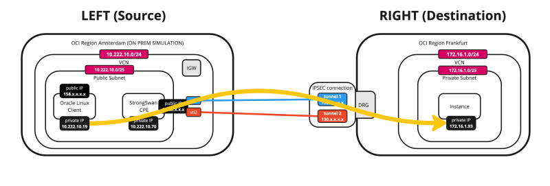
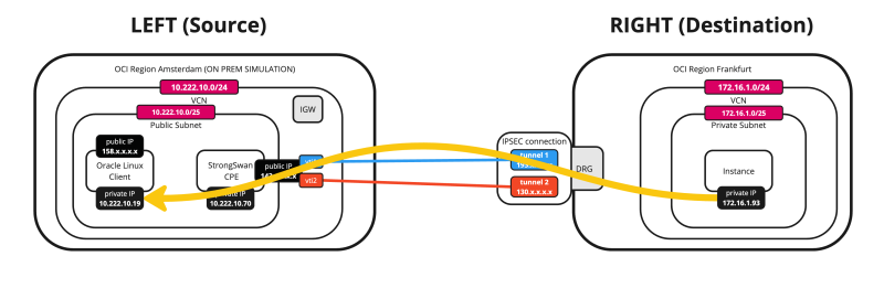
Below is a visual representation of what we have discussed so far.
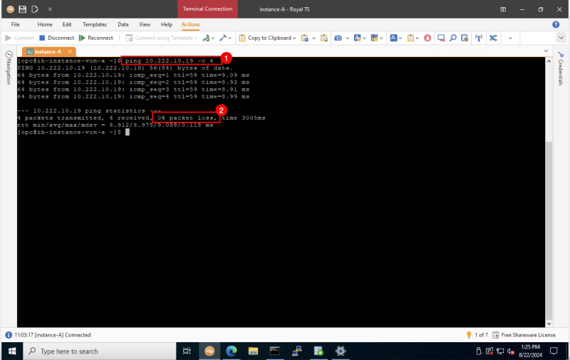
- Issue the following command from the DESTINATION to verify if the ping is working from the Destination OCI Region to the Source OCI Region (CLIENT).
- Notice that we have 0% packet loss.
[opc@ih-instance-vcn-a ~]$ ping 10.222.10.19 -c 4
Below is a visual representation of what we have discussed so far.
STEP 12 - Look at the OCI dashboards to verify the Site-to-site VPN status
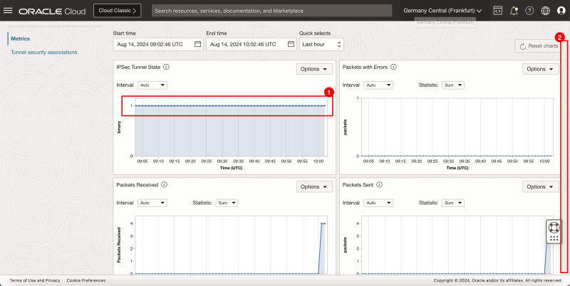
Now that the VPN Tunnels are up and traffic is flowing through then we can look at the dashboards in OCI on a per-tunnel basis.
- Browse to the Site-to-Site settings on the OCI Console by going through Networking > Customer Connectivity > Site-to-Site VPN.
- Click on the VPN connection.
- Click on the first tunnel configuration.
- Scroll down.
- Notice the IPSEC Tunnel State graph is constantly on 1, indicating the tunnel is up.
- Scroll down.
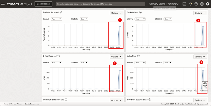
- Notice the Packets Received on this tunnel is 4, which corresponds with the number of ping packets I sent from the source.
- Notice the Packets Sent on this tunnel is 4, which corresponds with the number of ping packets I sent from the destination.
- Notice the number of Bytes Received from the source.
- Notice the number of Bytes Sent from the destination.
STEP 13 - Enable ECMP Routing
- By default, the traffic is always sent using one tunnel interface (vti). If we want to use both tunnels for traffic forwarding we need to enable the Equal Cost Multi-Path (ECMP) routing on both sides.
On the Libreswan CPE issue this command:
[root@cpe ipsec.d]# sysctl -w net.ipv4.fib_multipath_hash_policy=1
Below is a visual representation of what we have discussed so far.
On the destination OCI Region:
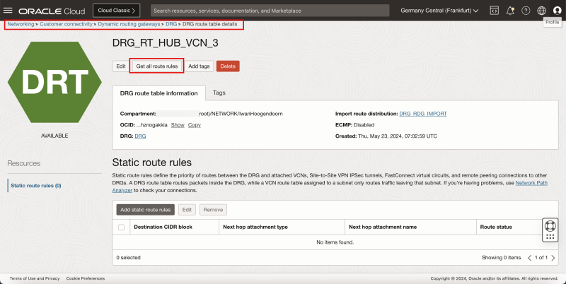
- Browse to the DRG on the OCI Console by going through Networking > Customer Connectivity > Dynamic routing gateway > Select the DRG > DRG route table > Select the DRG route table that is responsible for the routing
- Click on the Get all route rules button.
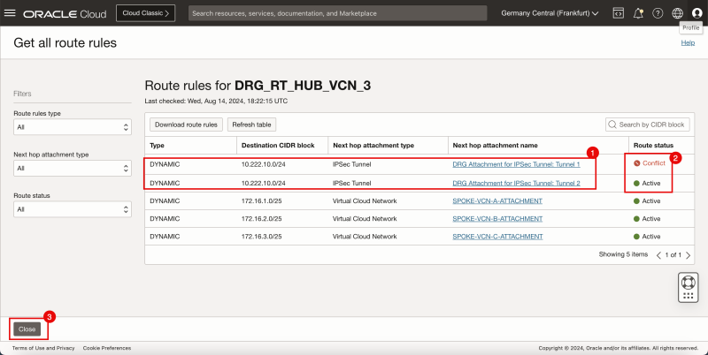
- Notice that there are two routes available for the 1`0.222.10.0/24` network.
- Notice that one route rule for the `10.222.10.0/24` is marked as Conflict and the other as Active.
- Click on the Close button.
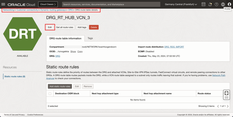
- Click on the Edit button.
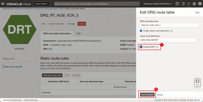
- Check the box to Enable ECMP.
- Click on the Save Changes button.
- Click on the Get all route rules button.
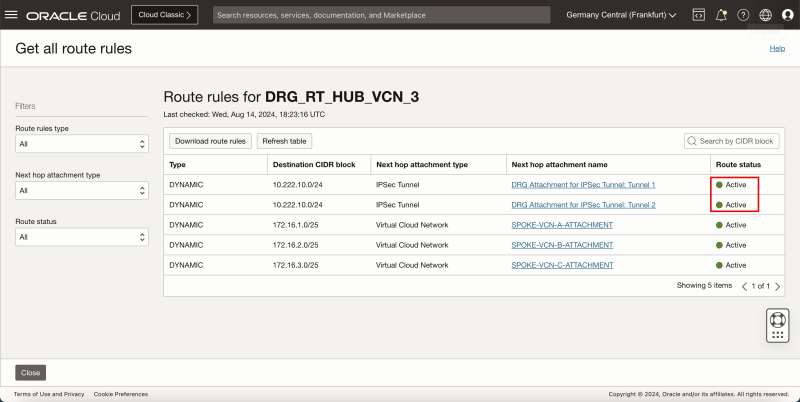
- Notice that both route rules for the `10.222.10.0/24` are now marked as Active.
Below is a visual representation of what we have discussed so far.
Conclusion
In this tutorial, we have connected two different OCI regions using an IPSEC VPN with two tunnels and with ECMP enabled. We used a CPE with Libreswan software in one OCI Region and the Site-to-Site VPN configured on the DRG in the other Region.
