Route Hub and Spoke VCN with pfSense Firewall in the Hub VCN
Hub and spoke routing within a cloud provider can be confusing and hard to configure. To achieve this we need to configure multiple objects with different types of configuration. Network routing and network security across multiple levels inside the cloud make this confusing.
In this tutorial, we will explain how to configure a hub VCN with three-spoke VCNs. The hub VCN will contain the pfSense firewall and the connection to the internet and OCI services network. All network traffic originating from the spoke VCN that needs to communicate with other spoke VCNs or with the Internet or the OCI services network needs to pass the hub VCN for firewall inspection.

The following images illustrate the traffic flows.
- Spoke to spoke connectivity

- Spoke to Hub connectivity

- Hub to Spoke connectivity

- Spoke to Internet connectivity

- Spoke to Service connectivity

- Hub to Internet connectivity

- Internet to Hub connectivity

<aside>
In this tutorial, we will use several networks in the spokes.
- Spoke A VCN subnet: `172.16.1.0/25`.
- Spoke B VCN subnet: `172.16.2.0/25`.
- Spoke C VCN subnet: `172.16.3.0/25`.
</aside>
Objectives
- Set up an OCI routing environment with hub and spoke routing fully configured. We will route all network traffic to the hub VCN where the hub VCN will contain a firewall that will inspect all the traffic coming from the spokes.
- Task 1: Create the hub and spoke VCNs.
- Task 2: Create the subnets inside the hub and spoke VCNs.
- Task 3: Create a DRG, internet gateway, and a NAT gateway.
- Task 4: Add instances attached to different subnets inside all VCNs.
- Task 5: Add a pfSense firewall in the hub VCN.
- Task 6: Open firewall rules on the security lists.
- Task 7: Configure routing between the different VCNs and the internet with hub firewall inspection.
- Task 8: Verify the connectivity.
Task 1 - Create the Hub and Spoke VCNs
- Log in to the OCI Console and click Virtual cloud Networking or click the hamburger menu (≡), Networking and Virtual cloud networks.

- Click Create VCN to create the VCN.

1. Enter the Name for the hub VCN.
2. Enter an IPv4 CIDR Block for the hub VCN.
3. Scroll down.

- Click Create VCN.

1. Notice that the hub VCN is AVAILABLE.
2. Click Virtual Cloud Networks to return to the VCN page.

- The following image illustrates the visual representation of what you have created so far.

Now, we will create three spoke VCNs (Spoke A, Spoke B, and Spoke C).
- Click Create VCN to create the first spoke VCN (Spoke A).

1. Enter the Name for the spoke VCN.
2. Enter an IPv4 CIDR Block for the spoke VCN.
3. Click Create VCN.

1. Notice that the spoke VCN is AVAILABLE.
2. Click Virtual Cloud Networks to return to the VCN page.

- Click Create VCN to create the second spoke VCN (Spoke B).

1. Enter the Name for the spoke VCN.
2. Enter an IPv4 CIDR Block for the hub VCN.
3. Click Create VCN.

1. Notice that the spoke VCN is AVAILABLE.
2. Click Virtual Cloud Networks to return to the VCN page.

1. Click Create VCN to create the third spoke VCN.
2. Enter the Name for the spoke VCN.
3. Enter an IPv4 CIDR Block for the hub VCN.
4. Click Create VCN.

1. Notice that the spoke VCN is AVAILABLE.
2. Click Virtual Cloud Networks to return to the VCN page.

- Notice that we have created 1 hub and 3 spoke VCNs.

- The following image illustrates the visual representation of what you have created so far.

Task 2 - Create the Subnets inside the Hub and Spoke VCNs
We have the hub and spoke VCNs in place. Now, create subnets inside the VCNs.
Create a Subnet inside Hub VCN
In the hub VCN we will create 1 private subnet and 1 public subnet.
- Click the hub VCN.

- Click Create Subnet to create the first subnet (private).

1. Enter the Name for the private subnet.
2. In Subnet Type, select Regional.
3. Enter IPv4 CIDR Block for the private subnet.
4. Scroll down.

1. In Route Table, select the default route table.
2. In Subnet Access, select a Private Subnet.
3. Scroll down.

1. In DHCP options, select the default DHCP options.
2. In Security List, select the default security list.
3. Click Create Subnet.

- Notice that the state is set to Provisioning.

1. After a few minutes the state is changed to Available.
2. Click Create Subnet to create the second subnet (public).

1. Enter the Name for the private subnet.
2. In Subnet Type, select Regional.
3. Enter IPv4 CIDR Block for the public subnet.
4. Scroll down.

1. In Route Table, select the default route table.
2. In Subnet Access, select a Public Subnet.
3. Scroll down.

1. In DHCP options, select the default DHCP options.
2. In Security List, select the default security list.
3. Click Create Subnet.

- Notice that the state is set to Provisioning.

- After a few minutes the state is changed to Available.

- The following image illustrates the visual representation of what you have created so far.

Create a Subnet in Spoke VCN A
Create one private subnet inside the spoke VCN A.
- Click the spoke VCN A.

- Click Create Subnet to create the subnet (private).

1. Enter the Name for the private subnet.
2. Enter IPv4 CIDR Block for the private subnet.
3. Scroll down.

1. In Route Table, select the default route table.
2. In Subnet Access, select a Private Subnet.
3. Scroll down.

1. In DHCP options, select the default DHCP options.
2. In Security List, select the default security list.
3. Click Create Subnet.

- Notice that the state is set to Provisioning.

1. Notice that the state is changed to Available.
2. Click Virtual Cloud Networks to return to the VCN page.

- The following image illustrates the visual representation of what you have created so far.

Create a Subnet in Spoke VCN B
Create one private subnet inside the spoke VCN B.
- Click the spoke VCN B.

- Click Create Subnet to create the subnet (private).

1. Enter the Name for the private subnet.
2. Enter IPv4 CIDR Block for the private subnet.
3. Scroll down.

1. In Route Table, select the default route table.
2. In Subnet Access, select a Private Subnet.
3. Scroll down.

1. In DHCP options, select the default DHCP options.
2. In Security List, select the default security list.
3. Click Create Subnet.

- Notice that the state is set to Provisioning.

1. Notice that the state is changed to Available.
2. Click Virtual Cloud Networks to return to the VCN page.

- The following image illustrates the visual representation of what you have created so far.

Create Subnet inside Hub VCN C
Create one private subnet inside the spoke VCN C.
- Click the spoke VCN C.

- Click Create Subnet to create the subnet (private).

1. Enter the Name for the private subnet.
2. Enter IPv4 CIDR Block for the private subnet.
3. Scroll down.

1. In Route Table, select the default route table.
2. In Subnet Access, select a Private Subnet.
3. Scroll down.

1. In DHCP options, select the default DHCP options.
2. In Security List, select the default security list.
3. Click Create Subnet.

- Notice that the state is set to Provisioning.

- Notice that the state is changed to Available.

- The following image illustrates the visual representation of what you have created so far.

Task 3 - Create a Dynamic Routing Gateway -DRG- and Internet Gateway and a NAT Gateway in the Hub VCN
Create a DRG that will be used to route traffic between the VCNs. We also need to create an internet gateway and a NAT gateway for our access to the Internet.
- Click the hub VCN.
- Click Internet Gateways.

1. Click Create Internet Gateway.
2. Enter the Name of the internet gateway.
3. Click Create Internet Gateway.

1. Notice that the state is Available.

- The following image illustrates the visual representation of what you have created so far.

1. We are inside the hub VCN configuration page after internet gateway creation. Scroll down.
2. Click NAT Gateways.
3. Click Create NAT Gateway.

1. Enter the Name of the NAT Gateway.
2. Select Ephemeral Public IP Address.
3. Click Create NAT Gateway.

1. Notice that the state is Available.

- The following image illustrates the visual representation of what you have created so far.

- Create the Dynamic Routing Gateway (DRG).
1. Click the hamburger menu (≡) icon from the upper left corner.
2. Click Networking.
3. Click Dynamic routing gateway.

- Click Create dynamic routing gateway.

1. Enter the Name of the dynamic routing gateway.
2. Click Create dynamic routing gateway.

1. Notice that the state is PROVISIONING.

- Notice that the state is changed to AVAILABLE.

- The following image illustrates the visual representation of what you have created so far.

Task 4 - Add Instances attached to different Subnets inside all VCNs
We will add various OCI Compute instances in all the VCNs so we can test out the routing flows.
Create Instance in Hub VCN
In the hub VCN, we will create a Windows compute instance that will have two main functions:
- The Windows instance will act as a stepstone machine to access the other instances inside our OCI environment.
- The Windows instance will also be a network endpoint that can be used for testing the routing flows.
Windows Instance as Step Stone
To create a Windows instance (hub-step-stone) that can act as a stepping stone inside your OCI environment, use [Deploy a Windows Instance in Oracle Cloud Infrastructure.]
Create the Windows stepping stone instance (hub-step-stone) before you continue with the tutorial.
The following image illustrates the visual representation of what you have created so far.

Create Instance in Hub VCN Spoke VCN A
In the spoke VCN A, we will create a simple Linux instance that will act as a network endpoint that we can use to test our routing flows.
Spoke A Client Instance
- Create a instance.
1. Click the hamburger menu (≡) icon from the upper left corner.
2. Click Compute.
3. Click Instances.

- Click Create Instance.

1. Enter the Name of the instance.
2. Scroll down.

- Scroll down.

1. In Primary network, select Select existing virtual cloud network.
2. In VCN, select SPOKE-VCN-A.
3. In Subnet, select Select existing subnet.
4. Select Private Subnet from the spoke VCN A.
5. Scroll down.

1. In Private IPv4 address, select Automatically assign private IPv4 address.
2. Scroll down.

1. In Add SSH keys, select Generate a key pair for me.
2. Click Save private key to save the private key locally.
3. Click Save public key to save the public key locally.

- Make sure the keys are stored somewhere locally.
We will use the same key pair for the other spoke instances.

- Scroll down.

- Click Create.

- Notice that the state is PROVISIONING.

1. Notice that the state is changed to RUNNING.
2. Note the Private IP address for later.
3. Click Instances to return to the instances page.

1. Notice that the Instance A is running.
2. Click Create Instance to create the next instance.

- The following image illustrates the visual representation of what you have created so far.

Create Instance in Spoke VCN B
In the Spoke VCN B, we will create a simple Linux Instance that will act as a network endpoint that we can use to test our routing flows.
Spoke B Client Instance
- Create an instance.
1. Enter the Name of the instance.
2. Scroll down.

- Scroll down.

1. In Primary network, select Select existing virtual cloud network.
2. In VCN, select SPOKE-VCN-B.
3. In Subnet, select Select existing subnet.
4. Select the Private Subnet from spoke VCN B.
5. Scroll down.

1. In Private IPv4 address, select Automatically assign private IPv4 address.
2. Scroll down.

1. Upload public key files.
2. Click Browse. Select the public key file you saved when you created instance A.
3. Make sure the public key is selected.
4. Scroll down.

- Scroll down.

- Click Create.

- Note that the state is PROVISIONING.

1. Note that the state is changed RUNNING.
2. Note the Private IP address to be used in a later step.
3. Click Instances to return to the instances page.

1. Note that Instance B is Running.
2. Click Create Instance to create the next instance.

- The following image illustrates the visual representation of what you have created so far.

Create Instance in Spoke VCN C
In the Spoke VCN C, we will create a simple Linux instance that will act as a network endpoint that we can use to test our routing flows.
Spoke C Client Instance
- Create an instance.
1. Enter a name of the instance.
2. Scroll down.

- Scroll down.

1. In Primary network, select Select existing virtual cloud network.
2. In VCN, select SPOKE-VCN-C.
3. In Subnet, select Select existing subnet.
4. Select the Private Subnet from the spoke VCN C.
5. Scroll down.

1. In Private IPv4 address, select Automatically assign private IPv4 address.
2. Scroll down.

1. Upload public key files.
2. Click Browse. Select the public key file you saved when you created instance A.
3. Make sure the public key is selected
4. Scroll down.

- Scroll down.

- Click Create.

- Notice that the state is PROVISIONING.

1. Notice that the state is changed to RUNNING.
2. Note the Private IP address for later.
3. Click Instances to return to the instances page

- Notice that the Instance C is running.

- The following image illustrates the visual representation of what you have created so far.

Task 5 - Add a pfSense Firewall Instance in the Hub VCN
The last instance we need for our network setup is a firewall. For example, this can be any firewall like the OCI Network Firewall. In this tutorial, we will use the pfSense firewall.
To create a pfSense instance (`hub-fw`) which can act as a firewall inside your OCI environment, use [this tutorial.]
Create the pfSense instance before you continue the tutorial.
The following image illustrates the visual representation of what you have created so far.

Task 6 - Open Firewall Rules on the Security Lists
In an OCI environment, there are multiple layers of network security. By default, all ingress network traffic is blocked for most protocols and ports. To make testing with ping possible we will open the ICMP ports on the hub and spoke VCNs so that we can allow all ICMP traffic that is coming into the VCN.
Add Ingress Rule in Hub VCN
- Go to the OCI Console.
1. Click the hamburger menu (≡) from the upper left corner.
2. Click Virtual Cloud Networks or navigate to Networking and Virtual Cloud Networks.

- Select the hub VCN to which your pfSense firewall is attached.

1. Scroll down.
2. Click Security Lists.
3. Click Default Security List for HUB-VCN.

- Click Add Ingress Rules.

1. In Source Type, select CIDR.
2. In Source CIDR, enter `0.0.0.0/0`.
3. In IP Protocol, select ICMP.
4. Click Add Ingress Rules.

- Note the ICMP rules is added.

- Click Virtual cloud networks to return to the VCN page.

- The following image illustrates the visual representation of what you have created so far.

Add Ingress Rule in Spoke VCN A
- Click the spoke VCN A.

1. Scroll down.
2. Click Security Lists.
3. Click Default Security List for SPOKE-VCN-A

- Click Add Ingress Rules.

1. In Source Type, select CIDR.
2. In Source CIDR, enter `0.0.0.0/0`.
3. In IP Protocol, select ICMP.
4. Click Add Ingress Rules.

- Notice the ICMP rule is added.

- The following image illustrates the visual representation of what you have created so far.

Add Ingress Rules in Spoke VCN B
- Click the spoke VCN B.

1. Scroll down.
2. Click Security Lists.
3. Click Default Security List for SPOKE-VCN-B

- Click Add Ingress Rules.

1. In Source Type, select CIDR.
2. In Source CIDR, enter `0.0.0.0/0`.
3. In IP Protocol, select ICMP.
4. Click Add Ingress Rules.

- Note the ICMP rule is added.

- The following image illustrates the visual representation of what you have created so far.

Add Ingress Rules in Spoke VCN C
- Click spoke VCN C.

1. Scroll down.
2. Click Security Lists.
3. Click Default Security List for SPOKE-VCN-C

- Click Add Ingress Rules.

1. In Source Type, select CIDR.
2. In Source CIDR, enter `0.0.0.0/0`.
3. In IP Protocol, select ICMP.
4. Click Add Ingress Rules.

- Note the ICMP rule is added.

- The following image illustrates the visual representation of what you have created so far.

Task 7 - Configure Routing between the different VCNs and the Internet with Hub Firewall Inspection
We already have all the required components. Now, we need to configure routing. Before we can configure routing we need to first attach the VCNs to the DRG.
After this, we will create the attachments that we need to create different VCN routing tables, DRG routing tables and to associate these routing tables to different VCNs, DRG VCN attachments, subnets, and gateways.
Task 7-1 - Create VCN Attachments on DRG
- Create VCN attachments on the DRG.
1. Click the hamburger menu (≡) from the upper left corner.
2. Click Networking.
3. Click Dynamic Routing Gateway.

- Click the DRG created in Task 3.

1. Click VCN attachments.
2. Click Create virtual network attachment.

1. Enter a Attachment name for the hub VCN.
2. Select the hub VCN.
3. Click Create VCN attachment.

- Notice that the hub VCN state is Attaching.

- The following image illustrates the visual representation of what you have created so far.

1. Notice that the hub VCN state changed to Attached.
2. Click Create virtual network attachment to create the next attachment.

1. Enter Attachment name for the spoke VCN A.
2. Select the spoke VCN A.
3. Click Create VCN attachment.

- Note that the spoke VCN A state is Attaching.

- The following image illustrates the visual representation of what you have created so far.

1. Note that the spoke VCN A state has changed to Attached.
2. Click Create virtual network attachment to create the next attachment.

1. Enter Attachment name for the spoke VCN B.
2. Select the spoke VCN B.
3. Click Create VCN attachment.

- Note that the spoke VCN B state is Attaching.

- The following image illustrates the visual representation of what you have created so far.

1. Note that the spoke VCN B state has changed to Attached.
2. Click Create virtual network attachment to create the next attachment.

1. Enter a Attachment name for spoke VCN C.
2. Select spoke VCN C.
3. Click Create VCN attachment.

- Note that the spoke VCN C state is Attaching.

- Note that the spoke VCN C state has changed to Attached.

- The following image illustrates the visual representation of what you have created so far.

Task 7-2 - Create and Configure Spoke VCN Routing Tables
We need to create two types of routing tables: VCN Routing Tables and DRG Routing Tables.
By default when you create a VCN, a default routing table is created.
- Spoke VCN A only has the default VCN routing table.
| Destination | Target Type | Target | Route Type |
|---|---|---|---|
| 0.0.0.0/0 | Dynamic Route Gateway | DRG | Static |
1. Click the hamburger menu (≡) from the upper left corner.
2. Click Networking.
3. Click Virtual cloud networks.

- Click spoke VCN A.

1. Click Route Tables.
2. Click Default route table for SPOKE-VCN-A.

- Click Add Route Rules.

1. In Target Type, select the Dynamic Routing Gateway.
2. In Destination Type, select CIDR Block.
3. In Destination CIDR Block, enter `0.0.0.0/0`.
4. Click Add Route Rules.
- This rule will route all traffic coming from spoke VCN A to the DRG.

1. Note that the `0.0.0.0/0` route is now added to the default route table of spoke VCN A.
2. Click Virtual cloud networks to return to the VCN page.

- The following image illustrates the visual representation of what you have created so far.

- Spoke VCN B only has the default VCN routing table.
| Destination | Target Type | Target | Route Type |
|---|---|---|---|
| 0.0.0.0/0 | Dynamic Route Gateway | DRG | Static |
- Click spoke VCN B.

1. Click Route Tables.
2. Click Default Route Table from SPOKE-VCN-B.

- Click Add Route Rules.

1. In Target Type, select the Dynamic Routing Gateway.
2. In Destination Type, select CIDR Block.
3. In Destination CIDR Block, enter `0.0.0.0/0`.
4. Click Add Route Rules.
- This rule will route all traffic coming from spoke VCN B to the DRG.

1. Note that the `0.0.0.0/0` route is now added to the default route table of spoke VCN B.
2. Click Virtual cloud networks to return to the VCN page.

- The following image illustrates the visual representation of what you have created so far.

- Spoke VCN C only has the default VCN routing table.
| Destination | Target Type | Target | Route Type |
|---|---|---|---|
| 0.0.0.0/0 | Dynamic Route Gateway | DRG | Static |
- Click spoke VCN C.

1. Click Route Tables.
2. Click Default Route Table for SPOKE-VCN-C.

- Click Add Route Rules.

1. In Target Type, select the Dynamic Routing Gateway.
2. In Destination Type, select CIDR Block.
3. In Destination CIDR Block, enter `0.0.0.0/0`.
4. Click Add Route Rules.
- This rule will route all traffic coming from spoke VCN C to the DRG.

- Note that the `0.0.0.0/0` route is now added to the default route table of spoke VCN C.

- The following image illustrates the visual representation of what you have created so far.

Task 7-3 - Create and Configure Hub VCN Routing Tables
- Create a route table (`VCN_HUB_RT_DRG_TRANSIT`) in the Hub VCN.
| Destination | Target Type | Target | Route Type |
|---|---|---|---|
| 0.0.0.0/0 | Private IP | 172.16.0.20 (FW IP) | Static |
| 172.16.1.0/24 | Private IP | 172.16.0.20 (FW IP) | Static |
| 172.16.2.0/24 | Private IP | 172.16.0.20 (FW IP) | Static |
| 172.16.3.0/24 | Private IP | 172.16.0.20 (FW IP) | Static |
{{note|To route the traffic that is going from spoke to spoke VCN's we also need to add in the specific routes in this route table as the default `0.0.0.0/0` is not enough to make this work.}
- Go to the OCI Console.
1. Click the hamburger menu (≡) from the upper left corner.
2. Click Networking.
3. Click Virtual cloud networks.

- Click the hub VCN.

1. Click Route Tables.
2. Click Create Route Table.

1. Enter the Name of the new hub VCN route table.
2. Click + Another Route Rule (not in the screenshot).
3. In Target Type, select Private IP.
4. Scroll down.

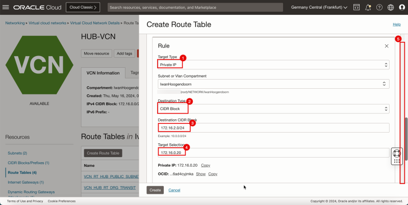
1. In Destination Type, select CIDR Block.
2. In Destination CIDR Block, enter `0.0.0.0/0`.
3. In Target Selection, enter `172.16.0.20` (this is the IP address of our pfSense firewall).
4. Click Create.

1. Note that you will get the following error: `PrivatelP (ocid 1.privateip.oc1.eu-frankfurt-1.abtheljtrcahk23t4vtbeguxxxxxxxxxxxxxxxxxvwbgypf36ad4cyjmka) is an invalid route target. (The Private IP is attached to a VNIC whose SRC/DST check is enabled)`.
2. Click Cancel.

- To fix this, we need to enable the skip source/destination check on the pfSense firewall instance VNIC.
1. Click the hamburger menu (≡).
2. Click Compute.
3. Click Instances.

- Click the `hub-fw` (pfSense instance).

- Scroll down.

1. Click Attached VNICs.
2. Click the three dots of the VNIC.
3. Click Edit VNIC.

1. Select Skip source/destination check.
2. Click Save changes.

- Now, create the hub VNC routing tables.
1. Click the hamburger menu (≡) from the upper left corner.
2. Click Networking.
3. Click Virtual cloud networks.

- Click the hub VCN.

1. Click Route Tables.
2. Click Create Route Table.

1. Enter the Name for the new hub VCN route table.
2. Click + Another Route Rule.

1. InTarget Type, select Private IP.
2. Scroll down.

1. In Destination Type, select CIDR Block.
2. In Destination CIDR Block, enter `0.0.0.0/0`.
3. In Target Selection, enter `172.16.0.20` (this is the IP address of our pfSense firewall).
4. Click Create.

- We need to add three more routes to the `VCN_HUB_RT_DRG_TRANSIT` route table.
- Click Add Route Rules.

1. In Target Type, select Private IP.
2. In Destination Type, select CIDR Block.
3. In Destination CIDR Block, enter `172.16.1.0/24`.
4. In Target Selection, enter `172.16.0.20` (this is the IP address of our pfSense firewall).
5. Click + Another Route Rule.

1. In Target Type, select Private IP.
2. In Destination Type, select CIDR Block.
3. In Destination CIDR Block, enter `172.16.2.0/24`.
4. In Target Selection, enter `172.16.0.20` (this is the IP address of our pfSense firewall).
5. Click + Another Route Rule.

1. In Target Type, select Private IP.
2. In Destination Type, select CIDR Block.
3. In Destination CIDR Block, enter `172.16.3.0/24`.
4. In Target Selection, enter `172.16.0.20` (this is the IP address of our pfSense firewall).
5. Click + Another Route Rule.

1. Note that the 4 route rules created.
2. Click the Hub VCN to return to the Hub VCN page.

1. Note that the hub VCN routing table is now in the list.
2. Click Create Route Table again to create another hub VCN route table for the public subnet.

- The following image illustrates the visual representation of what you have created so far.

- Create a route table (`VCN_RT_HUB_PUBLIC_SUBNET`) in the hub VCN.
| Destination | Target Type | Target | Route Type |
|---|---|---|---|
| 0.0.0.0/0 | Internet Gateway | hub-internet-gateway | Static |
| 172.16.1.0/24 | Private IP | 172.16.0.20 (FW IP) | Static |
| 172.16.2.0/24 | Private IP | 172.16.0.20 (FW IP) | Static |
| 172.16.3.0/24 | Private IP | 172.16.0.20 (FW IP) | Static |
- Create route table.
1. Enter the Name for the new hub VCN route table for the public subnet.
2. Click + Another Route Rule.

1. In Target Type, select Internet Gateway.
2. In Destination CIDR Block, enter `0.0.0.0/0`.
3. Scroll down.

1. In Target Internet Gateway, select the internet gateway you created earlier.
2. Click + Another Route Rule.

1. In Target Type, select Private IP.
2. In Destination Type, select CIDR Block.
3. In Destination CIDR Block, enter `172.16.1.0/24`.
4. In Target Selection, enter `172.16.0.20` (this is the IP address of our pfSense firewall).
5. Scroll down.

- Click + Another Route Rule.

1. In Target Type, select Private IP.
2. In Destination Type, select CIDR Block.
3. In Destination CIDR Block, enter `172.16.2.0/24`.
4. In Target Selection, enter `172.16.0.20` (this is the IP address of our pfSense firewall).
5. Scroll down.

- Click + Another Route Rule.

1. In Target Type, select Private IP.
2. In Destination Type, select CIDR Block.
3. In Destination CIDR Block, enter `172.16.3.0/24`.
4. In Target Selection, enter `172.16.0.20` (this is the IP address of our pfSense firewall).
5. Scroll down.

1. Note that the route table for the public subnet is created. Click the routing table name.
2. Also, note that this routing table contains 4 routing rules.

- Note if the 4 route rules are present.

1. Scroll up.
2. Click the Hub VCN to return to the Hub VCN page.

- The following image illustrates the visual representation of what you have created so far.

- Create a route table (`VCN_HUB_RT_NAT_TRANSIT`) in the Hub VCN.
| Destination | Target Type | Target | Route Type |
|---|---|---|---|
| 172.16.1.0/24 | Private IP | 172.16.0.20 (FW IP) | Static |
| 172.16.2.0/24 | Private IP | 172.16.0.20 (FW IP) | Static |
| 172.16.3.0/24 | Private IP | 172.16.0.20 (FW IP) | Static |
1. Click Route Tables.
2. Click Create Route Table again to create another hub VCN route table for the NAT gateway.

1. Enter the Name for the new hub VCN route table for the NAT gateway.
2. Click + Another Route Rule.

1. In Target Type, select Private IP.
2. In Destination Type, select CIDR Block.
3. In Destination CIDR Block, enter `172.16.1.0/24`.
4. In Target Selection, enter `172.16.0.20` (this is the IP address of our pfSense firewall).
5. Scroll down.

- Click + Another Route Rule.

1. In Target Type, select Private IP.
2. In Destination Type, select CIDR Block.
3. In Destination CIDR Block, enter `172.16.2.0/24`.
4. In Target Selection, enter `172.16.0.20` (this is the IP address of our pfSense firewall).
5. Scroll down.

- Click + Another Route Rule.

1. In Target Type, select Private IP.
2. In Destination Type, select CIDR Block.
3. In Destination CIDR Block, enter `172.16.3.0/24`.
4. In Target Selection, enter `172.16.0.20` (this is the IP address of our pfSense firewall).
5. Scroll down.

1. Note that the route table for the NAT gateway is created. Click the routing table name.
2. Also, note that this routing table contains 3 routing rules.

1. Note the 3 route rules we created.
2. Click Hub VCN to return to the Hub VCN page.

- The following image illustrates the visual representation of what you have created so far.

- Create a route table (`VCN_RT_HUB_PRIVATE_SUBNET`) in the Hub VCN.
| Destination | Target Type | Target | Route Type |
|---|---|---|---|
| 0.0.0.0/0 | NAT Gateway | hub-nat-gw | Static |
| 172.16.1.0/24 | Dynamic Route Gateway | DRG | Static |
| 172.16.2.0/24 | Dynamic Route Gateway | DRG | Static |
| 172.16.3.0/24 | Dynamic Route Gateway | DRG | Static |
1. Click Route Tables.
2. Click the routing table for the private subnet. If you do not have this table, then create it. To create the route table, click Create Route Table.

1. Note that there is already one route rule present that will route all traffic (`0.0.0.0/0`) to the NAT gateway for the private subnet instances.
2. Click Add Route Rules.

1. In Target Type, select Dynamic Routing Gateway.
2. In Destination Type, select CIDR Block.
3. In Destination CIDR Block, enter `172.16.1.0/24`.
4. Click + Another Route Rule.

1. In Target Type, select Dynamic Routing Gateway.
2. In Destination Type, select CIDR Block.
3. In Destination CIDR Block, enter `172.16.2.0/24`.
4. Click + Another Route Rule.

1. In Target Type, select Dynamic Routing Gateway.
2. In Destination Type, select CIDR Block.
3. In Destination CIDR Block, enter `172.16.3.0/24`.
4. Click Add Route Rules.

- Note all the route rules for the private subnet routing table.

- The following image illustrates the visual representation of what you have created so far.

Task 7-4 - Create and Configure DRG Routing Tables
- Create a route distribution group (`DRG_RDG_IMPORT`) in the DRG.
| Priority | Match Type | Match Criteria | Action |
|---|---|---|---|
| 1 | Attachment | SPOKE_VCN-A_ATTACHMENT | ACCEPT |
| 2 | Attachment | SPOKE_VCN-B_ATTACHMENT | ACCEPT |
| 3 | Attachment | SPOKE_VCN-C_ATTACHMENT | ACCEPT |
1. Click the hamburger menu (≡) from the upper left corner.
2. Click Networking.
3. Click Dynamic routing gateway.

- Click the DRG created in Task 3.

1. Click Import route distribution.
2. Click Create import route distribution.

- In the Create import route distribution page, enter the following information.
1. Enter the Name for the route distribution.
2. Create a new route distribution statement.
   - Priority: Enter 1.
   - Match Type: Select Attachment.
   - Attachment type filter: Select Virtual Cloud Network.
   - DRG attachment: Select spoke VCN A.
   - Action: Select Accept.
3. Create a new route distribution statement
   - Priority: Enter 2.
   - Match Type: Select Attachment.
   - Attachment type filter: Select Virtual Cloud Network.
   - DRG attachment: Select spoke VCN B.
   - Action: Select Accept.
4. Create a new route distribution statement
   - Priority: Enter 3.
   - Match Type: Select Attachment.
   - Attachment type filter: Select Virtual Cloud Network.
   - DRG attachment: Select spoke VCN C.
   - Action: Select Accept.
5. Click Create import route distribution.

- Click the new import route distribution.

1. Note the route distribution statements.
2. Click Dynamic routing gateways details to return to the DRG details page.

- The following image illustrates the visual representation of what you have created so far.

- Create a route table (`DRG_RT_SPOKE_VCN_2`) in the DRG.
| Destination CIDR | Next Hop Attachment Type | Next Hop Attachment Name |
|---|---|---|
| 0.0.0.0/0 | Virtual Cloud Network | HUB_VCN_ATTACHMENT |
1. Click DRG route tables.
2. Click Create DRG route table.

1. Enter the Name for the DRG route table.
2. Add a new static rule:
   - Destination CIDR Block: Enter `0.0.0.0/0`.
   - Next hop attachment type: Select Virtual Cloud Network
   - Next hop attachment: Select hub VCN.
3. Click Create DRG route table.

- Wait for the creation of the route table.

1. Note that the new DRG route table is created.
2. Click Create DRG route table to create another DRG routing table.

- The following image illustrates the visual representation of what you have created so far.

- Create a route table (`DRG_RT_HUB_VCN_3`) in the DRG and import the route distribution group (`DRG_RDG_IMPORT`).
1. Enter the Name for the DRG route table.
2. Click Show Advanced options.

- Import the Import Route Distribution created earlier.
1. Click Route table settings.
2. Select Enable import route distribution.
3. Select the import route distribution created earlier.
4. Click Create DRG route table.

1. Notice that the new DRG route table is created.

- The following image illustrates the visual representation of what you have created so far.

Task 7-5 - Attach the Route Tables
Now that we have created route tables, we need to attach the route tables to the DRG, VCNs, subnets, and gateways.
This is where routing is activated, so this is a careful process that needs to be thought of first and properly tested before you implement or make changes in a Production environment.
Attach the DRG Route Tables:
Let us first attach the DRG routing tables.
Attach DRG Routing Tables to the Spoke VCN Attachments
Routing Information: (`DRG_RT_SPOKE_VCN_2`) This DRG route table and route table attachment will make sure that all traffic that is coming from the spoke VCNs, is now routed to the hub VCN.
First, we are going to attach the ()`DRG_RT_SPOKE_VCN_2`) DRG Routing table to all the spoke VCN attachments.
- Go to the DRG page. Click Networking, Dynamic Routing Gateway and select the DRG created earlier.
1. Click VCN attachments.
2. Click the VCN attachment for Spoke A.

1. Note that the VCN attachment for Spoke A has the autogenerated DRG table associated. We need to change this.
2. Click Edit.

- Click Show Advanced options.

1. Select the DRG route table.
2. Select the DRG route table created earlier: `DRG_RT_SPOKE_VCN_2`.
3. Click Save Changes.

1. Note that a new DRG route table is active on the spoke A VCN attachment.
2. Click DRG to return to the DRG details page.

- The following image illustrates the visual representation of what you have created so far.

- Click the VCN attachment for spoke B.

1. Note that the VCN Attachment for spoke B has the autogenerated DRG table associated. We need to change this.
2. Click Edit.

1. Click Show Advanced options.
2. Select the DRG route table tab.
3. Select the DRG route table created earlier (`DRG_RT_SPOKE_VCN_2`).
4. Click Save Changes.

1. Note that a new DRG route table is active on the spoke B VCN attachment.
2. Click DRG to return to the DRG details page.

- The following image illustrates the visual representation of what you have created so far.

- Click the VCN attachment for spoke C.

1. Note that the VCN attachment for spoke C has the autogenerated DRG table associated. We need to change this.
2. Click Edit.

1. Click Show Advanced options.
2. Select the DRG route table tab.
3. Select the DRG route table created earlier (`DRG_RT_SPOKE_VCN_2`).
4. Click Save Changes.

1. Note that a new DRG route table is active on the spoke VCN C attachment.
2. Click DRG to return to the DRG details page.

- The following image illustrates the visual representation of what you have created so far.

Attach DRG Routing Tables to the Hub VCN Attachment
We will attach the ()`DRG_RT_HUB_VCN_3`) DRG route table to the hub VCN attachment. We are also going to attach the (`VCN_HUB_RT_DRG_TRANSIT`) VCN route table to the hub VCN attachment.
Routing Information: (`DRG_RT_HUB_VCN_3`) This DRG route table and route table attachment will make sure that all networks from the spokes are known on the DRG and learned on the DRG so that the DRG knows what networks are available on the spokes and so it knows where to route the spoke networks to.
Routing Information: (`VCN_HUB_RT_DRG_TRANSIT`) This VCN route table and route table attachment will make sure that all traffic is routed to the firewall in the hub.
- Go to the DRG page. Click Networking, Dynamic Routing Gateway and select the DRG created earlier.
1. Click VCN attachments.
2. Click the VCN attachment for the hub.

1. Note that the VCN attachment for the hub has the autogenerated DRG table associated. We need to change this.
2. Note that the VCN attachment for the hub has no VCN table associated. We need to add this.
3. Click Edit.

1. Click Show Advanced options.
2. Select the DRG route table tab.
3. Select the DRG route table created earlier (`DRG_RT_HUB_VCN_3`).
4. Click the VCN route table tab.

1. Select Select existing to select an existing VCN route table.
2. Select the VCN route table created earlier (`VCN_HUB_RT_DRG_TRANSIT`).
3. Click Save Changes.

1. Note that a new DRG route table is active on the hub VCN attachment.
2. Note that a new VCN route table is active on the hub VCN attachment.

- The following image illustrates the visual representation of what you have created so far.

Attach the VCN Route Tables:
Now, we are going to attach the VCN route tables even though we already started doing this for one of the VCN route tables in the previous task.
Attach VCN Routing Tables to the Hub VCN Public Subnet
Attach the (`VCN_RT_HUB_PUBLIC_SUBNET`) VCN route table to the the public subnet in the hub VCN.
Routing Information: (`VCN_RT_HUB_PUBLIC_SUBNET`) This VCN route table will route traffic that is destined for the spokes to the firewall. Traffic that is destined to the internet (all traffic other than spoke networks) to the internet gateway will also be routed by this route table.
- Go to the OCI Console.
1. Click the hamburger menu (≡) from the upper left corner.
2. Click Networking.
3. Click Virtual cloud networks.

- Click the hub VCN.

1. Click Subnets.
2. Click Public hub Subnet.

1. Notice the public hub subnet has the default VCN table associated. We need to change this.
2. Click Edit.

1. Select the VCN route table created earlier (`VCN_RT_HUB_PUBLIC_SUBNET`).
2. Click Save Changes.

1. Notice that a new VCN route table is active on the hub public subnet.
2. Click Hub VCN to return to the Hub VCN details page.

- The following image illustrates the visual representation of what you have created so far.

Attach VCN Routing Tables to the Hub VCN Private Subnet
Next, we are going to attach the (`VCN_RT_HUB_PRIVATE_SUBNET`) VCN route table to the private subnet in the hub VCN.
Routing Information: (`VCN_RT_HUB_PRIVATE_SUBNET`) This VCN route table will route traffic that is destined for the spokes to the firewall. Traffic that is destined to the internet (all traffic other than spoke networks) to the NAT gateway will also be routed by this route table.
- Go to the hub VCN.
1. Click Private hub Subnet.

1. Notice the private hub subnet has the VCN route table associated already. If you still have the default VCN table associated then change this. To change, click Edit and change this to `VCN_RT_HUB_PRIVATE_SUBNET`.
2. Scroll down.

- The following image illustrates the visual representation of what you have created so far.

Attach VCN Routing Tables to the Hub VCN NAT Gateway
Attach the (`VCN_HUB_RT_NAT_TRANSIT`) VCN route table to the NAT gateway in the hub VCN.
Routing Information: (`VCN_HUB_RT_NAT_TRANSIT`) This VCN route table will route traffic that is destined for the spokes to the firewall.
- Go to the OCI Console.
1. Click NAT Gateways.
2. Notice that the NAT gateway does not have any route table associated.
3. Click the three dots.
4. Click Associate Route Table.

1. Select the VCN route table created earlier (`VCN_HUB_RT_NAT_TRANSIT`).
2. Click Associate Route Table.

- Note that a new VCN route table is active on the hub NAT gateway.

- The following image illustrates the visual representation of what you have created so far.

Attach VCN Routing Tables to the Spoke VCN Private Subnets
We already configured the default spoke VCN routing tables in one of the previous tasks. The spoke (A, B, and C) private subnets will automatically use the default VCN route table and there is no need to change this. We can do a quick check.
Go to the OCI Console, navigate to Networking and Virtual cloud Networks.
- Click spoke VCN A.

- Click spoke A Private Subnet.

1. Note that the Default Route table for Spoke VCN A is used.
2. Click Virtual Cloud Networks to return to the VCN page.

- Click spoke VCN B.

- Click spoke B Private Subnet.

1. Note that the Default Route table for Spoke VCN B is used.
2. Click Virtual Cloud Networks to return to the VCN page.

- Click spoke VCN C.

- Click spoke C Private Subnet.

- Note that the Default Route table for Spoke VCN C is used.

- The following image illustrates the visual representation of what you have created so far.

Hub and spoke routing within a cloud provider can be confusing and hard to configure. To achieve this we need to configure multiple objects with different types of configuration. Network routing and network security across multiple levels inside the cloud make this confusing.
In this tutorial, we will explain how to configure a hub VCN with three-spoke VCNs. The hub VCN will contain the pfSense firewall and the connection to the internet and OCI services network. All network traffic originating from the spoke VCN that needs to communicate with other spoke VCNs or with the Internet or the OCI services network needs to pass the hub VCN for firewall inspection.
The following images illustrate the traffic flows.
- Spoke to spoke connectivity
- Spoke to Hub connectivity
- Hub to Spoke connectivity
- Spoke to Internet connectivity
- Spoke to Service connectivity
- Hub to Internet connectivity
- Internet to Hub connectivity
<aside>
In this tutorial, we will use several networks in the spokes.
- Spoke A VCN subnet: `172.16.1.0/25`.
- Spoke B VCN subnet: `172.16.2.0/25`.
- Spoke C VCN subnet: `172.16.3.0/25`.
</aside>
Objectives
- Set up an OCI routing environment with hub and spoke routing fully configured. We will route all network traffic to the hub VCN where the hub VCN will contain a firewall that will inspect all the traffic coming from the spokes.
- Task 1: Create the hub and spoke VCNs.
- Task 2: Create the subnets inside the hub and spoke VCNs.
- Task 3: Create a DRG, internet gateway, and a NAT gateway.
- Task 4: Add instances attached to different subnets inside all VCNs.
- Task 5: Add a pfSense firewall in the hub VCN.
- Task 6: Open firewall rules on the security lists.
- Task 7: Configure routing between the different VCNs and the internet with hub firewall inspection.
- Task 8: Verify the connectivity.
Task 1 - Create the Hub and Spoke VCNs
- Log in to the OCI Console and click Virtual cloud Networking or click the hamburger menu (≡), Networking and Virtual cloud networks.
- Click Create VCN to create the VCN.
1. Enter the Name for the hub VCN.
2. Enter an IPv4 CIDR Block for the hub VCN.
3. Scroll down.
- Click Create VCN.
1. Notice that the hub VCN is AVAILABLE.
2. Click Virtual Cloud Networks to return to the VCN page.
- The following image illustrates the visual representation of what you have created so far.
Now, we will create three spoke VCNs (Spoke A, Spoke B, and Spoke C).
- Click Create VCN to create the first spoke VCN (Spoke A).
1. Enter the Name for the spoke VCN.
2. Enter an IPv4 CIDR Block for the spoke VCN.
3. Click Create VCN.
1. Notice that the spoke VCN is AVAILABLE.
2. Click Virtual Cloud Networks to return to the VCN page.
- Click Create VCN to create the second spoke VCN (Spoke B).
1. Enter the Name for the spoke VCN.
2. Enter an IPv4 CIDR Block for the hub VCN.
3. Click Create VCN.
1. Notice that the spoke VCN is AVAILABLE.
2. Click Virtual Cloud Networks to return to the VCN page.
1. Click Create VCN to create the third spoke VCN.
2. Enter the Name for the spoke VCN.
3. Enter an IPv4 CIDR Block for the hub VCN.
4. Click Create VCN.
1. Notice that the spoke VCN is AVAILABLE.
2. Click Virtual Cloud Networks to return to the VCN page.
- Notice that we have created 1 hub and 3 spoke VCNs.
- The following image illustrates the visual representation of what you have created so far.
Task 2 - Create the Subnets inside the Hub and Spoke VCNs
We have the hub and spoke VCNs in place. Now, create subnets inside the VCNs.
Create a Subnet inside Hub VCN
In the hub VCN we will create 1 private subnet and 1 public subnet.
- Click the hub VCN.
- Click Create Subnet to create the first subnet (private).
1. Enter the Name for the private subnet.
2. In Subnet Type, select Regional.
3. Enter IPv4 CIDR Block for the private subnet.
4. Scroll down.
1. In Route Table, select the default route table.
2. In Subnet Access, select a Private Subnet.
3. Scroll down.
1. In DHCP options, select the default DHCP options.
2. In Security List, select the default security list.
3. Click Create Subnet.
- Notice that the state is set to Provisioning.
1. After a few minutes the state is changed to Available.
2. Click Create Subnet to create the second subnet (public).
1. Enter the Name for the private subnet.
2. In Subnet Type, select Regional.
3. Enter IPv4 CIDR Block for the public subnet.
4. Scroll down.
1. In Route Table, select the default route table.
2. In Subnet Access, select a Public Subnet.
3. Scroll down.
1. In DHCP options, select the default DHCP options.
2. In Security List, select the default security list.
3. Click Create Subnet.
- Notice that the state is set to Provisioning.
- After a few minutes the state is changed to Available.
- The following image illustrates the visual representation of what you have created so far.
Create a Subnet in Spoke VCN A
Create one private subnet inside the spoke VCN A.
- Click the spoke VCN A.
- Click Create Subnet to create the subnet (private).
1. Enter the Name for the private subnet.
2. Enter IPv4 CIDR Block for the private subnet.
3. Scroll down.
1. In Route Table, select the default route table.
2. In Subnet Access, select a Private Subnet.
3. Scroll down.
1. In DHCP options, select the default DHCP options.
2. In Security List, select the default security list.
3. Click Create Subnet.
- Notice that the state is set to Provisioning.
1. Notice that the state is changed to Available.
2. Click Virtual Cloud Networks to return to the VCN page.
- The following image illustrates the visual representation of what you have created so far.
Create a Subnet in Spoke VCN B
Create one private subnet inside the spoke VCN B.
- Click the spoke VCN B.
- Click Create Subnet to create the subnet (private).
1. Enter the Name for the private subnet.
2. Enter IPv4 CIDR Block for the private subnet.
3. Scroll down.
1. In Route Table, select the default route table.
2. In Subnet Access, select a Private Subnet.
3. Scroll down.
1. In DHCP options, select the default DHCP options.
2. In Security List, select the default security list.
3. Click Create Subnet.
- Notice that the state is set to Provisioning.
1. Notice that the state is changed to Available.
2. Click Virtual Cloud Networks to return to the VCN page.
- The following image illustrates the visual representation of what you have created so far.
Create Subnet inside Hub VCN C
Create one private subnet inside the spoke VCN C.
- Click the spoke VCN C.
- Click Create Subnet to create the subnet (private).
1. Enter the Name for the private subnet.
2. Enter IPv4 CIDR Block for the private subnet.
3. Scroll down.
1. In Route Table, select the default route table.
2. In Subnet Access, select a Private Subnet.
3. Scroll down.
1. In DHCP options, select the default DHCP options.
2. In Security List, select the default security list.
3. Click Create Subnet.
- Notice that the state is set to Provisioning.
- Notice that the state is changed to Available.
- The following image illustrates the visual representation of what you have created so far.
Task 3 - Create a Dynamic Routing Gateway -DRG- and Internet Gateway and a NAT Gateway in the Hub VCN
Create a DRG that will be used to route traffic between the VCNs. We also need to create an internet gateway and a NAT gateway for our access to the Internet.
- Click the hub VCN.
- Click Internet Gateways.
1. Click Create Internet Gateway.
2. Enter the Name of the internet gateway.
3. Click Create Internet Gateway.
1. Notice that the state is Available.
- The following image illustrates the visual representation of what you have created so far.
1. We are inside the hub VCN configuration page after internet gateway creation. Scroll down.
2. Click NAT Gateways.
3. Click Create NAT Gateway.
1. Enter the Name of the NAT Gateway.
2. Select Ephemeral Public IP Address.
3. Click Create NAT Gateway.
1. Notice that the state is Available.
- The following image illustrates the visual representation of what you have created so far.
- Create the Dynamic Routing Gateway (DRG).
1. Click the hamburger menu (≡) icon from the upper left corner.
2. Click Networking.
3. Click Dynamic routing gateway.
- Click Create dynamic routing gateway.
1. Enter the Name of the dynamic routing gateway.
2. Click Create dynamic routing gateway.
1. Notice that the state is PROVISIONING.
- Notice that the state is changed to AVAILABLE.
- The following image illustrates the visual representation of what you have created so far.
Task 4 - Add Instances attached to different Subnets inside all VCNs
We will add various OCI Compute instances in all the VCNs so we can test out the routing flows.
Create Instance in Hub VCN
In the hub VCN, we will create a Windows compute instance that will have two main functions:
- The Windows instance will act as a stepstone machine to access the other instances inside our OCI environment.
- The Windows instance will also be a network endpoint that can be used for testing the routing flows.
Windows Instance as Step Stone
To create a Windows instance (hub-step-stone) that can act as a stepping stone inside your OCI environment, use [Deploy a Windows Instance in Oracle Cloud Infrastructure.]
Create the Windows stepping stone instance (hub-step-stone) before you continue with the tutorial.
The following image illustrates the visual representation of what you have created so far.
Create Instance in Hub VCN Spoke VCN A
In the spoke VCN A, we will create a simple Linux instance that will act as a network endpoint that we can use to test our routing flows.
Spoke A Client Instance
- Create a instance.
1. Click the hamburger menu (≡) icon from the upper left corner.
2. Click Compute.
3. Click Instances.
- Click Create Instance.
1. Enter the Name of the instance.
2. Scroll down.
- Scroll down.
1. In Primary network, select Select existing virtual cloud network.
2. In VCN, select SPOKE-VCN-A.
3. In Subnet, select Select existing subnet.
4. Select Private Subnet from the spoke VCN A.
5. Scroll down.
1. In Private IPv4 address, select Automatically assign private IPv4 address.
2. Scroll down.
1. In Add SSH keys, select Generate a key pair for me.
2. Click Save private key to save the private key locally.
3. Click Save public key to save the public key locally.
- Make sure the keys are stored somewhere locally.
We will use the same key pair for the other spoke instances.
- Scroll down.
- Click Create.
- Notice that the state is PROVISIONING.
1. Notice that the state is changed to RUNNING.
2. Note the Private IP address for later.
3. Click Instances to return to the instances page.
1. Notice that the Instance A is running.
2. Click Create Instance to create the next instance.
- The following image illustrates the visual representation of what you have created so far.
Create Instance in Spoke VCN B
In the Spoke VCN B, we will create a simple Linux Instance that will act as a network endpoint that we can use to test our routing flows.
Spoke B Client Instance
- Create an instance.
1. Enter the Name of the instance.
2. Scroll down.
- Scroll down.
1. In Primary network, select Select existing virtual cloud network.
2. In VCN, select SPOKE-VCN-B.
3. In Subnet, select Select existing subnet.
4. Select the Private Subnet from spoke VCN B.
5. Scroll down.
1. In Private IPv4 address, select Automatically assign private IPv4 address.
2. Scroll down.
1. Upload public key files.
2. Click Browse. Select the public key file you saved when you created instance A.
3. Make sure the public key is selected.
4. Scroll down.
- Scroll down.
- Click Create.
- Note that the state is PROVISIONING.
1. Note that the state is changed RUNNING.
2. Note the Private IP address to be used in a later step.
3. Click Instances to return to the instances page.
1. Note that Instance B is Running.
2. Click Create Instance to create the next instance.
- The following image illustrates the visual representation of what you have created so far.
Create Instance in Spoke VCN C
In the Spoke VCN C, we will create a simple Linux instance that will act as a network endpoint that we can use to test our routing flows.
Spoke C Client Instance
- Create an instance.
1. Enter a name of the instance.
2. Scroll down.
- Scroll down.
1. In Primary network, select Select existing virtual cloud network.
2. In VCN, select SPOKE-VCN-C.
3. In Subnet, select Select existing subnet.
4. Select the Private Subnet from the spoke VCN C.
5. Scroll down.
1. In Private IPv4 address, select Automatically assign private IPv4 address.
2. Scroll down.
1. Upload public key files.
2. Click Browse. Select the public key file you saved when you created instance A.
3. Make sure the public key is selected
4. Scroll down.
- Scroll down.
- Click Create.
- Notice that the state is PROVISIONING.
1. Notice that the state is changed to RUNNING.
2. Note the Private IP address for later.
3. Click Instances to return to the instances page
- Notice that the Instance C is running.
- The following image illustrates the visual representation of what you have created so far.
Task 5 - Add a pfSense Firewall Instance in the Hub VCN
The last instance we need for our network setup is a firewall. For example, this can be any firewall like the OCI Network Firewall. In this tutorial, we will use the pfSense firewall.
To create a pfSense instance (`hub-fw`) which can act as a firewall inside your OCI environment, use [this tutorial.]
Create the pfSense instance before you continue the tutorial.
The following image illustrates the visual representation of what you have created so far.
Task 6 - Open Firewall Rules on the Security Lists
In an OCI environment, there are multiple layers of network security. By default, all ingress network traffic is blocked for most protocols and ports. To make testing with ping possible we will open the ICMP ports on the hub and spoke VCNs so that we can allow all ICMP traffic that is coming into the VCN.
Add Ingress Rule in Hub VCN
- Go to the OCI Console.
1. Click the hamburger menu (≡) from the upper left corner.
2. Click Virtual Cloud Networks or navigate to Networking and Virtual Cloud Networks.
- Select the hub VCN to which your pfSense firewall is attached.
1. Scroll down.
2. Click Security Lists.
3. Click Default Security List for HUB-VCN.
- Click Add Ingress Rules.
1. In Source Type, select CIDR.
2. In Source CIDR, enter `0.0.0.0/0`.
3. In IP Protocol, select ICMP.
4. Click Add Ingress Rules.
- Note the ICMP rules is added.
- Click Virtual cloud networks to return to the VCN page.
- The following image illustrates the visual representation of what you have created so far.
Add Ingress Rule in Spoke VCN A
- Click the spoke VCN A.
1. Scroll down.
2. Click Security Lists.
3. Click Default Security List for SPOKE-VCN-A
- Click Add Ingress Rules.
1. In Source Type, select CIDR.
2. In Source CIDR, enter `0.0.0.0/0`.
3. In IP Protocol, select ICMP.
4. Click Add Ingress Rules.
- Notice the ICMP rule is added.
- The following image illustrates the visual representation of what you have created so far.
Add Ingress Rules in Spoke VCN B
- Click the spoke VCN B.
1. Scroll down.
2. Click Security Lists.
3. Click Default Security List for SPOKE-VCN-B
- Click Add Ingress Rules.
1. In Source Type, select CIDR.
2. In Source CIDR, enter `0.0.0.0/0`.
3. In IP Protocol, select ICMP.
4. Click Add Ingress Rules.
- Note the ICMP rule is added.
- The following image illustrates the visual representation of what you have created so far.
Add Ingress Rules in Spoke VCN C
- Click spoke VCN C.
1. Scroll down.
2. Click Security Lists.
3. Click Default Security List for SPOKE-VCN-C
- Click Add Ingress Rules.
1. In Source Type, select CIDR.
2. In Source CIDR, enter `0.0.0.0/0`.
3. In IP Protocol, select ICMP.
4. Click Add Ingress Rules.
- Note the ICMP rule is added.
- The following image illustrates the visual representation of what you have created so far.
Task 7 - Configure Routing between the different VCNs and the Internet with Hub Firewall Inspection
We already have all the required components. Now, we need to configure routing. Before we can configure routing we need to first attach the VCNs to the DRG.
After this, we will create the attachments that we need to create different VCN routing tables, DRG routing tables and to associate these routing tables to different VCNs, DRG VCN attachments, subnets, and gateways.
Task 7-1 - Create VCN Attachments on DRG
- Create VCN attachments on the DRG.
1. Click the hamburger menu (≡) from the upper left corner.
2. Click Networking.
3. Click Dynamic Routing Gateway.
- Click the DRG created in Task 3.
1. Click VCN attachments.
2. Click Create virtual network attachment.
1. Enter a Attachment name for the hub VCN.
2. Select the hub VCN.
3. Click Create VCN attachment.
- Notice that the hub VCN state is Attaching.
- The following image illustrates the visual representation of what you have created so far.
1. Notice that the hub VCN state changed to Attached.
2. Click Create virtual network attachment to create the next attachment.
1. Enter Attachment name for the spoke VCN A.
2. Select the spoke VCN A.
3. Click Create VCN attachment.
- Note that the spoke VCN A state is Attaching.
- The following image illustrates the visual representation of what you have created so far.
1. Note that the spoke VCN A state has changed to Attached.
2. Click Create virtual network attachment to create the next attachment.
1. Enter Attachment name for the spoke VCN B.
2. Select the spoke VCN B.
3. Click Create VCN attachment.
- Note that the spoke VCN B state is Attaching.
- The following image illustrates the visual representation of what you have created so far.
1. Note that the spoke VCN B state has changed to Attached.
2. Click Create virtual network attachment to create the next attachment.
1. Enter a Attachment name for spoke VCN C.
2. Select spoke VCN C.
3. Click Create VCN attachment.
- Note that the spoke VCN C state is Attaching.
- Note that the spoke VCN C state has changed to Attached.
- The following image illustrates the visual representation of what you have created so far.
Task 7-2 - Create and Configure Spoke VCN Routing Tables
We need to create two types of routing tables: VCN Routing Tables and DRG Routing Tables.
By default when you create a VCN, a default routing table is created.
- Spoke VCN A only has the default VCN routing table.
| Destination | Target Type | Target | Route Type |
|---|---|---|---|
| 0.0.0.0/0 | Dynamic Route Gateway | DRG | Static |
1. Click the hamburger menu (≡) from the upper left corner.
2. Click Networking.
3. Click Virtual cloud networks.
- Click spoke VCN A.
1. Click Route Tables.
2. Click Default route table for SPOKE-VCN-A.
- Click Add Route Rules.
1. In Target Type, select the Dynamic Routing Gateway.
2. In Destination Type, select CIDR Block.
3. In Destination CIDR Block, enter `0.0.0.0/0`.
4. Click Add Route Rules.
- This rule will route all traffic coming from spoke VCN A to the DRG.
1. Note that the `0.0.0.0/0` route is now added to the default route table of spoke VCN A.
2. Click Virtual cloud networks to return to the VCN page.
- The following image illustrates the visual representation of what you have created so far.
- Spoke VCN B only has the default VCN routing table.
| Destination | Target Type | Target | Route Type |
|---|---|---|---|
| 0.0.0.0/0 | Dynamic Route Gateway | DRG | Static |
- Click spoke VCN B.
1. Click Route Tables.
2. Click Default Route Table from SPOKE-VCN-B.
- Click Add Route Rules.
1. In Target Type, select the Dynamic Routing Gateway.
2. In Destination Type, select CIDR Block.
3. In Destination CIDR Block, enter `0.0.0.0/0`.
4. Click Add Route Rules.
- This rule will route all traffic coming from spoke VCN B to the DRG.
1. Note that the `0.0.0.0/0` route is now added to the default route table of spoke VCN B.
2. Click Virtual cloud networks to return to the VCN page.
- The following image illustrates the visual representation of what you have created so far.
- Spoke VCN C only has the default VCN routing table.
| Destination | Target Type | Target | Route Type |
|---|---|---|---|
| 0.0.0.0/0 | Dynamic Route Gateway | DRG | Static |
- Click spoke VCN C.
1. Click Route Tables.
2. Click Default Route Table for SPOKE-VCN-C.
- Click Add Route Rules.
1. In Target Type, select the Dynamic Routing Gateway.
2. In Destination Type, select CIDR Block.
3. In Destination CIDR Block, enter `0.0.0.0/0`.
4. Click Add Route Rules.
- This rule will route all traffic coming from spoke VCN C to the DRG.
- Note that the `0.0.0.0/0` route is now added to the default route table of spoke VCN C.
- The following image illustrates the visual representation of what you have created so far.
Task 7-3 - Create and Configure Hub VCN Routing Tables
- Create a route table (`VCN_HUB_RT_DRG_TRANSIT`) in the Hub VCN.
| Destination | Target Type | Target | Route Type |
|---|---|---|---|
| 0.0.0.0/0 | Private IP | 172.16.0.20 (FW IP) | Static |
| 172.16.1.0/24 | Private IP | 172.16.0.20 (FW IP) | Static |
| 172.16.2.0/24 | Private IP | 172.16.0.20 (FW IP) | Static |
| 172.16.3.0/24 | Private IP | 172.16.0.20 (FW IP) | Static |
To route the traffic that is going from spoke to spoke VCN's we also need to add in the specific routes in this route table as the default `0.0.0.0/0` is not enough to make this work.
- Go to the OCI Console.
1. Click the hamburger menu (≡) from the upper left corner.
2. Click Networking.
3. Click Virtual cloud networks.
- Click the hub VCN.
1. Click Route Tables.
2. Click Create Route Table.
1. Enter the Name of the new hub VCN route table.
2. Click + Another Route Rule (not in the screenshot).
3. In Target Type, select Private IP.
4. Scroll down.
1. In Destination Type, select CIDR Block.
2. In Destination CIDR Block, enter `0.0.0.0/0`.
3. In Target Selection, enter `172.16.0.20` (this is the IP address of our pfSense firewall).
4. Click Create.
1. Note that you will get the following error: `PrivatelP (ocid 1.privateip.oc1.eu-frankfurt-1.abtheljtrcahk23t4vtbeguxxxxxxxxxxxxxxxxxvwbgypf36ad4cyjmka) is an invalid route target. (The Private IP is attached to a VNIC whose SRC/DST check is enabled)`.
2. Click Cancel.
- To fix this, we need to enable the skip source/destination check on the pfSense firewall instance VNIC.
1. Click the hamburger menu (≡).
2. Click Compute.
3. Click Instances.
- Click the `hub-fw` (pfSense instance).
- Scroll down.
1. Click Attached VNICs.
2. Click the three dots of the VNIC.
3. Click Edit VNIC.
1. Select Skip source/destination check.
2. Click Save changes.
- Now, create the hub VNC routing tables.
1. Click the hamburger menu (≡) from the upper left corner.
2. Click Networking.
3. Click Virtual cloud networks.
- Click the hub VCN.
1. Click Route Tables.
2. Click Create Route Table.
1. Enter the Name for the new hub VCN route table.
2. Click + Another Route Rule.
1. InTarget Type, select Private IP.
2. Scroll down.
1. In Destination Type, select CIDR Block.
2. In Destination CIDR Block, enter `0.0.0.0/0`.
3. In Target Selection, enter `172.16.0.20` (this is the IP address of our pfSense firewall).
4. Click Create.
- We need to add three more routes to the `VCN_HUB_RT_DRG_TRANSIT` route table.
- Click Add Route Rules.
1. In Target Type, select Private IP.
2. In Destination Type, select CIDR Block.
3. In Destination CIDR Block, enter `172.16.1.0/24`.
4. In Target Selection, enter `172.16.0.20` (this is the IP address of our pfSense firewall).
5. Click + Another Route Rule.
1. In Target Type, select Private IP.
2. In Destination Type, select CIDR Block.
3. In Destination CIDR Block, enter `172.16.2.0/24`.
4. In Target Selection, enter `172.16.0.20` (this is the IP address of our pfSense firewall).
5. Click + Another Route Rule.
1. In Target Type, select Private IP.
2. In Destination Type, select CIDR Block.
3. In Destination CIDR Block, enter `172.16.3.0/24`.
4. In Target Selection, enter `172.16.0.20` (this is the IP address of our pfSense firewall).
5. Click + Another Route Rule.
1. Note that the 4 route rules created.
2. Click the Hub VCN to return to the Hub VCN page.
1. Note that the hub VCN routing table is now in the list.
2. Click Create Route Table again to create another hub VCN route table for the public subnet.
- The following image illustrates the visual representation of what you have created so far.
- Create a route table (`VCN_RT_HUB_PUBLIC_SUBNET`) in the hub VCN.
| Destination | Target Type | Target | Route Type |
|---|---|---|---|
| 0.0.0.0/0 | Internet Gateway | hub-internet-gateway | Static |
| 172.16.1.0/24 | Private IP | 172.16.0.20 (FW IP) | Static |
| 172.16.2.0/24 | Private IP | 172.16.0.20 (FW IP) | Static |
| 172.16.3.0/24 | Private IP | 172.16.0.20 (FW IP) | Static |
- Create route table.
1. Enter the Name for the new hub VCN route table for the public subnet.
2. Click + Another Route Rule.
1. In Target Type, select Internet Gateway.
2. In Destination CIDR Block, enter `0.0.0.0/0`.
3. Scroll down.
1. In Target Internet Gateway, select the internet gateway you created earlier.
2. Click + Another Route Rule.
1. In Target Type, select Private IP.
2. In Destination Type, select CIDR Block.
3. In Destination CIDR Block, enter `172.16.1.0/24`.
4. In Target Selection, enter `172.16.0.20` (this is the IP address of our pfSense firewall).
5. Scroll down.
- Click + Another Route Rule.
1. In Target Type, select Private IP.
2. In Destination Type, select CIDR Block.
3. In Destination CIDR Block, enter `172.16.2.0/24`.
4. In Target Selection, enter `172.16.0.20` (this is the IP address of our pfSense firewall).
5. Scroll down.
- Click + Another Route Rule.
1. In Target Type, select Private IP.
2. In Destination Type, select CIDR Block.
3. In Destination CIDR Block, enter `172.16.3.0/24`.
4. In Target Selection, enter `172.16.0.20` (this is the IP address of our pfSense firewall).
5. Scroll down.
1. Note that the route table for the public subnet is created. Click the routing table name.
2. Also, note that this routing table contains 4 routing rules.
- Note if the 4 route rules are present.
1. Scroll up.
2. Click the Hub VCN to return to the Hub VCN page.
- The following image illustrates the visual representation of what you have created so far.
- Create a route table (`VCN_HUB_RT_NAT_TRANSIT`) in the Hub VCN.
| Destination | Target Type | Target | Route Type |
|---|---|---|---|
| 172.16.1.0/24 | Private IP | 172.16.0.20 (FW IP) | Static |
| 172.16.2.0/24 | Private IP | 172.16.0.20 (FW IP) | Static |
| 172.16.3.0/24 | Private IP | 172.16.0.20 (FW IP) | Static |
1. Click Route Tables.
2. Click Create Route Table again to create another hub VCN route table for the NAT gateway.
1. Enter the Name for the new hub VCN route table for the NAT gateway.
2. Click + Another Route Rule.
1. In Target Type, select Private IP.
2. In Destination Type, select CIDR Block.
3. In Destination CIDR Block, enter `172.16.1.0/24`.
4. In Target Selection, enter `172.16.0.20` (this is the IP address of our pfSense firewall).
5. Scroll down.
- Click + Another Route Rule.
1. In Target Type, select Private IP.
2. In Destination Type, select CIDR Block.
3. In Destination CIDR Block, enter `172.16.2.0/24`.
4. In Target Selection, enter `172.16.0.20` (this is the IP address of our pfSense firewall).
5. Scroll down.
- Click + Another Route Rule.
1. In Target Type, select Private IP.
2. In Destination Type, select CIDR Block.
3. In Destination CIDR Block, enter `172.16.3.0/24`.
4. In Target Selection, enter `172.16.0.20` (this is the IP address of our pfSense firewall).
5. Scroll down.
1. Note that the route table for the NAT gateway is created. Click the routing table name.
2. Also, note that this routing table contains 3 routing rules.
1. Note the 3 route rules we created.
2. Click Hub VCN to return to the Hub VCN page.
- The following image illustrates the visual representation of what you have created so far.
- Create a route table (`VCN_RT_HUB_PRIVATE_SUBNET`) in the Hub VCN.
| Destination | Target Type | Target | Route Type |
|---|---|---|---|
| 0.0.0.0/0 | NAT Gateway | hub-nat-gw | Static |
| 172.16.1.0/24 | Dynamic Route Gateway | DRG | Static |
| 172.16.2.0/24 | Dynamic Route Gateway | DRG | Static |
| 172.16.3.0/24 | Dynamic Route Gateway | DRG | Static |
1. Click Route Tables.
2. Click the routing table for the private subnet. If you do not have this table, then create it. To create the route table, click Create Route Table.
1. Note that there is already one route rule present that will route all traffic (`0.0.0.0/0`) to the NAT gateway for the private subnet instances.
2. Click Add Route Rules.
1. In Target Type, select Dynamic Routing Gateway.
2. In Destination Type, select CIDR Block.
3. In Destination CIDR Block, enter `172.16.1.0/24`.
4. Click + Another Route Rule.
1. In Target Type, select Dynamic Routing Gateway.
2. In Destination Type, select CIDR Block.
3. In Destination CIDR Block, enter `172.16.2.0/24`.
4. Click + Another Route Rule.
1. In Target Type, select Dynamic Routing Gateway.
2. In Destination Type, select CIDR Block.
3. In Destination CIDR Block, enter `172.16.3.0/24`.
4. Click Add Route Rules.
- Note all the route rules for the private subnet routing table.
- The following image illustrates the visual representation of what you have created so far.
Task 7-4 - Create and Configure DRG Routing Tables
- Create a route distribution group (`DRG_RDG_IMPORT`) in the DRG.
| Priority | Match Type | Match Criteria | Action |
|---|---|---|---|
| 1 | Attachment | SPOKE_VCN-A_ATTACHMENT | ACCEPT |
| 2 | Attachment | SPOKE_VCN-B_ATTACHMENT | ACCEPT |
| 3 | Attachment | SPOKE_VCN-C_ATTACHMENT | ACCEPT |
1. Click the hamburger menu (≡) from the upper left corner.
2. Click Networking.
3. Click Dynamic routing gateway.
- Click the DRG created in Task 3.
1. Click Import route distribution.
2. Click Create import route distribution.
- In the Create import route distribution page, enter the following information.
1. Enter the Name for the route distribution.
2. Create a new route distribution statement.
   - Priority: Enter 1.
   - Match Type: Select Attachment.
   - Attachment type filter: Select Virtual Cloud Network.
   - DRG attachment: Select spoke VCN A.
   - Action: Select Accept.
3. Create a new route distribution statement
   - Priority: Enter 2.
   - Match Type: Select Attachment.
   - Attachment type filter: Select Virtual Cloud Network.
   - DRG attachment: Select spoke VCN B.
   - Action: Select Accept.
4. Create a new route distribution statement
   - Priority: Enter 3.
   - Match Type: Select Attachment.
   - Attachment type filter: Select Virtual Cloud Network.
   - DRG attachment: Select spoke VCN C.
   - Action: Select Accept.
5. Click Create import route distribution.
- Click the new import route distribution.
1. Note the route distribution statements.
2. Click Dynamic routing gateways details to return to the DRG details page.
- The following image illustrates the visual representation of what you have created so far.
- Create a route table (`DRG_RT_SPOKE_VCN_2`) in the DRG.
| Destination CIDR | Next Hop Attachment Type | Next Hop Attachment Name |
|---|---|---|
| 0.0.0.0/0 | Virtual Cloud Network | HUB_VCN_ATTACHMENT |
1. Click DRG route tables.
2. Click Create DRG route table.
1. Enter the Name for the DRG route table.
2. Add a new static rule:
   - Destination CIDR Block: Enter `0.0.0.0/0`.
   - Next hop attachment type: Select Virtual Cloud Network
   - Next hop attachment: Select hub VCN.
3. Click Create DRG route table.
- Wait for the creation of the route table.
1. Note that the new DRG route table is created.
2. Click Create DRG route table to create another DRG routing table.
- The following image illustrates the visual representation of what you have created so far.
- Create a route table (`DRG_RT_HUB_VCN_3`) in the DRG and import the route distribution group (`DRG_RDG_IMPORT`).
1. Enter the Name for the DRG route table.
2. Click Show Advanced options.
- Import the Import Route Distribution created earlier.
1. Click Route table settings.
2. Select Enable import route distribution.
3. Select the import route distribution created earlier.
4. Click Create DRG route table.
1. Notice that the new DRG route table is created.
- The following image illustrates the visual representation of what you have created so far.
Task 7-5 - Attach the Route Tables
Now that we have created route tables, we need to attach the route tables to the DRG, VCNs, subnets, and gateways.
This is where routing is activated, so this is a careful process that needs to be thought of first and properly tested before you implement or make changes in a Production environment.
Attach the DRG Route Tables:
Let us first attach the DRG routing tables.
Attach DRG Routing Tables to the Spoke VCN Attachments
Routing Information: (`DRG_RT_SPOKE_VCN_2`) This DRG route table and route table attachment will make sure that all traffic that is coming from the spoke VCNs, is now routed to the hub VCN.
First, we are going to attach the ()`DRG_RT_SPOKE_VCN_2`) DRG Routing table to all the spoke VCN attachments.
- Go to the DRG page. Click Networking, Dynamic Routing Gateway and select the DRG created earlier.
1. Click VCN attachments.
2. Click the VCN attachment for Spoke A.
1. Note that the VCN attachment for Spoke A has the autogenerated DRG table associated. We need to change this.
2. Click Edit.
- Click Show Advanced options.
1. Select the DRG route table.
2. Select the DRG route table created earlier: `DRG_RT_SPOKE_VCN_2`.
3. Click Save Changes.
1. Note that a new DRG route table is active on the spoke A VCN attachment.
2. Click DRG to return to the DRG details page.
- The following image illustrates the visual representation of what you have created so far.
- Click the VCN attachment for spoke B.
1. Note that the VCN Attachment for spoke B has the autogenerated DRG table associated. We need to change this.
2. Click Edit.
1. Click Show Advanced options.
2. Select the DRG route table tab.
3. Select the DRG route table created earlier (`DRG_RT_SPOKE_VCN_2`).
4. Click Save Changes.
1. Note that a new DRG route table is active on the spoke B VCN attachment.
2. Click DRG to return to the DRG details page.
- The following image illustrates the visual representation of what you have created so far.
- Click the VCN attachment for spoke C.
1. Note that the VCN attachment for spoke C has the autogenerated DRG table associated. We need to change this.
2. Click Edit.
1. Click Show Advanced options.
2. Select the DRG route table tab.
3. Select the DRG route table created earlier (`DRG_RT_SPOKE_VCN_2`).
4. Click Save Changes.
1. Note that a new DRG route table is active on the spoke VCN C attachment.
2. Click DRG to return to the DRG details page.
- The following image illustrates the visual representation of what you have created so far.
Attach DRG Routing Tables to the Hub VCN Attachment
We will attach the ()`DRG_RT_HUB_VCN_3`) DRG route table to the hub VCN attachment. We are also going to attach the (`VCN_HUB_RT_DRG_TRANSIT`) VCN route table to the hub VCN attachment.
Routing Information: (`DRG_RT_HUB_VCN_3`) This DRG route table and route table attachment will make sure that all networks from the spokes are known on the DRG and learned on the DRG so that the DRG knows what networks are available on the spokes and so it knows where to route the spoke networks to.
Routing Information: (`VCN_HUB_RT_DRG_TRANSIT`) This VCN route table and route table attachment will make sure that all traffic is routed to the firewall in the hub.
- Go to the DRG page. Click Networking, Dynamic Routing Gateway and select the DRG created earlier.
1. Click VCN attachments.
2. Click the VCN attachment for the hub.
1. Note that the VCN attachment for the hub has the autogenerated DRG table associated. We need to change this.
2. Note that the VCN attachment for the hub has no VCN table associated. We need to add this.
3. Click Edit.
1. Click Show Advanced options.
2. Select the DRG route table tab.
3. Select the DRG route table created earlier (`DRG_RT_HUB_VCN_3`).
4. Click the VCN route table tab.
1. Select Select existing to select an existing VCN route table.
2. Select the VCN route table created earlier (`VCN_HUB_RT_DRG_TRANSIT`).
3. Click Save Changes.
1. Note that a new DRG route table is active on the hub VCN attachment.
2. Note that a new VCN route table is active on the hub VCN attachment.
- The following image illustrates the visual representation of what you have created so far.
Attach the VCN Route Tables:
Now, we are going to attach the VCN route tables even though we already started doing this for one of the VCN route tables in the previous task.
Attach VCN Routing Tables to the Hub VCN Public Subnet
Attach the (`VCN_RT_HUB_PUBLIC_SUBNET`) VCN route table to the the public subnet in the hub VCN.
Routing Information: (`VCN_RT_HUB_PUBLIC_SUBNET`) This VCN route table will route traffic that is destined for the spokes to the firewall. Traffic that is destined to the internet (all traffic other than spoke networks) to the internet gateway will also be routed by this route table.
- Go to the OCI Console.
1. Click the hamburger menu (≡) from the upper left corner.
2. Click Networking.
3. Click Virtual cloud networks.
- Click the hub VCN.
1. Click Subnets.
2. Click Public hub Subnet.
1. Notice the public hub subnet has the default VCN table associated. We need to change this.
2. Click Edit.
1. Select the VCN route table created earlier (`VCN_RT_HUB_PUBLIC_SUBNET`).
2. Click Save Changes.
1. Notice that a new VCN route table is active on the hub public subnet.
2. Click Hub VCN to return to the Hub VCN details page.
- The following image illustrates the visual representation of what you have created so far.
Attach VCN Routing Tables to the Hub VCN Private Subnet
Next, we are going to attach the (`VCN_RT_HUB_PRIVATE_SUBNET`) VCN route table to the private subnet in the hub VCN.
Routing Information: (`VCN_RT_HUB_PRIVATE_SUBNET`) This VCN route table will route traffic that is destined for the spokes to the firewall. Traffic that is destined to the internet (all traffic other than spoke networks) to the NAT gateway will also be routed by this route table.
- Go to the hub VCN.
1. Click Private hub Subnet.
1. Notice the private hub subnet has the VCN route table associated already. If you still have the default VCN table associated then change this. To change, click Edit and change this to `VCN_RT_HUB_PRIVATE_SUBNET`.
2. Scroll down.
- The following image illustrates the visual representation of what you have created so far.
Attach VCN Routing Tables to the Hub VCN NAT Gateway
Attach the (`VCN_HUB_RT_NAT_TRANSIT`) VCN route table to the NAT gateway in the hub VCN.
Routing Information: (`VCN_HUB_RT_NAT_TRANSIT`) This VCN route table will route traffic that is destined for the spokes to the firewall.
- Go to the OCI Console.
1. Click NAT Gateways.
2. Notice that the NAT gateway does not have any route table associated.
3. Click the three dots.
4. Click Associate Route Table.
1. Select the VCN route table created earlier (`VCN_HUB_RT_NAT_TRANSIT`).
2. Click Associate Route Table.
- Note that a new VCN route table is active on the hub NAT gateway.
- The following image illustrates the visual representation of what you have created so far.
Attach VCN Routing Tables to the Spoke VCN Private Subnets
We already configured the default spoke VCN routing tables in one of the previous tasks. The spoke (A, B, and C) private subnets will automatically use the default VCN route table and there is no need to change this. We can do a quick check.
Go to the OCI Console, navigate to Networking and Virtual cloud Networks.
- Click spoke VCN A.
- Click spoke A Private Subnet.
1. Note that the Default Route table for Spoke VCN A is used.
2. Click Virtual Cloud Networks to return to the VCN page.
- Click spoke VCN B.
- Click spoke B Private Subnet.
1. Note that the Default Route table for Spoke VCN B is used.
2. Click Virtual Cloud Networks to return to the VCN page.
- Click spoke VCN C.
- Click spoke C Private Subnet.
- Note that the Default Route table for Spoke VCN C is used.
- The following image illustrates the visual representation of what you have created so far.
Task 8 - Verify the Connectivity
The routing is configured for the full environment. Now, we can test if routing is working.
Task 8-1 - Connect to the Spoke Step Stone Instance with RDP
We connect to the Windows stepping stone using RDP through the internet. The traffic will be routed through the internet gateway.

When you are successfully connected, you will be able to see the desktop. From this desktop, we will perform some ping tests and perform management on the pfSense hub firewall.

Task 8-2 - Ping from Hub VCN to Spoke VCN
The first ping test that we are going to do is from the hub-step-stone to the spoke VCN instances.
- Due to routing configuration:
- The traffic will be sent to the pfSense firewall.
- The pfSense firewall will allow or deny the traffic based on the configured firewall rules.
- When the ICMP traffic is accepted it will route the traffic to the DRG.
- The DRG will then route the traffic to the correct spoke VCN.

1. Do a ping to spoke VCN instance A IP address from the hub-step-stone.
2. Notice that we have 0% packet loss so the ping is successful.
3. Do a ping to the spoke VCN instance B IP address from the hub-step-stone.
4. Notice that we have 0% packet loss so the ping is successful.
5. Do a ping to spoke VCN instance C IP address from the hub-step-stone.
6. Notice that we have 0% packet loss so the ping is successful.

- These pings are all successful because we have a firewall rule in place in the pfSense hub firewall that allows all ICMP traffic. When we created the pfSense firewall in this tutorial: [Install a pfSense Firewall in Oracle Cloud Infrastructure] we added this firewall rule.

Task 8-3 - Connect to the Spoke Instances with SSH
The ping (ICMP) is working in Task 8.2. Now, let us connect to the spoke instances with SSH because we also need to perform some connectivity tests from the spoke instances.
- Due to routing configuration:
- The traffic will be sent to the pfSense firewall.
- The pfSense firewall will allow or deny the traffic based on the configured firewall rules.
- When the SSH traffic is accepted it will route the traffic to the DRG.
- The DRG will then route the traffic to the correct spoke VCN.

- For this tutorial, I have preconfigured all the SSH sessions in Royal TSX application.

1. Connect to the spoke VCN A instance.
2. Note that the connection is trying to get through.

- Note that the connection is timing out. The reason for this is that we do not have a firewall rule in the pfSense hub firewall that allows TCP/`22` (SSH) traffic.

- Connect to the pfSense Management Console.
1. Click on the Firewall drop-down menu.
2. Click Rules.

- Click Add.

1. In Action, select Pass.
2. In Protocol, select TCP.

1. In Destination Network, enter `172.16.1.0/25`.
2. In Destination Port Range, select SSH (22).
3. Click Save.

1. Note that the firewall rule is now present to allow SSH to the spoke VCN A network.
2. Click Apply Changes.

- Note that the changes have been applied successfully.

1. Connect to the spoke VCN A instance again.
2. Notice that we get a question to cache the SSH fingerprint for the VCN A instance as this is our first connection ever.
3. Click Yes.

- Notice that the connection from the hub-step-stone towards the spoke A instance with SSH is now successful.

- We have only allowed the spoke A network, but we also need to add rules for the spoke B and spoke C networks. Go back to the psSense Management Console.
- Clone/Copy/Duplicate the rule we created to allow SSH to the spoke A VCN.

1. Change the Destination to `172.16.2.0/25`.
2. Click Save.

1. Note that the firewall rule is now present to allow SSH to the spoke VCN B network.
2. Click Apply Changes.

- Clone/Copy/Duplicate the rule we created to allow SSH to the spoke B VCN.

1. Change the Destination to `172.16.3.0/25`.
2. Click Save.

1. Note that the firewall rule is now present to allow SSH to the spoke VCN C network.
2. Click Apply Changes.

- Note that the changes have been applied successfully.

- Connect to all spoke instances with SSH.

Issue: SSH sessions are terminated after a few seconds. We noticed that the SSH connections were dropping after approximately 10 seconds and we troubleshooted this issue on multiple levels. We checked the security lists in OCI, routing in OCI, and the firewall rules in the pfSense. Eventually, we found that the SSH drops issue is related to pfSense.
- To solve the SSH drop issue, go to the pfSense Management Console.
1. Click on the System drop-down menu.
2. Click Advanced.

1. Click Firewall & NAT.
2. Select Clear invalid DF bits instead of dropping packets
3. In Firewall Optimization, select Conservative.
4. Scroll down.

- Click Save.

Task 8-4 - Ping from Spoke VCN to Hub VCN
Now, we have a stable connection from the spokes we can perform some ping tests from the spoke VCN instances.
- Due to routing configuration:
- The traffic will be sent to the DRG.
- The DRG will then route the traffic to the pfSense firewall.
- The pfSense firewall will allow or deny the traffic based on the configured firewall rules.
- When the ICMP traffic is accepted it will route the traffic to the hub-step-stone.

1. Do a ping to the hub-step-stone from the spoke A VCN instance.
2. Notice that we have 0% packet loss so the ping is successful.

1. Do a ping to the hub-step-stone from the spoke B VCN instance.
2. Notice that we have 0% packet loss so the ping is successful.

1. Do a ping to the hub-step-stone from the spoke C VCN instance.
2. Notice that we have 0% packet loss so the ping is successful.

Task 8-5 - Ping from Spoke VCN A to Spoke VCN B
Another ping test we can do is from one spoke to another spoke.
- Due to routing configuration:
- The traffic will be sent to the DRG from spoke VCN A.
- The DRG will then route the traffic to the pfSense firewall.
- The pfSense firewall will allow or deny the traffic based on the configured firewall rules.
- When the ICMP traffic is accepted it will route the traffic back to the DRG
- The DRG will route the traffic to spoke VCN B.

1. Do a ping to spoke B VCN instance from the spoke A VCN instance.
2. Notice that we have 0% packet loss so the ping is successful.

Task 8-6 - Ping from Spoke VCN to the Internet
Perform some ping tests from the spoke VCN instances towards the internet.
- Due to routing configuration:
- The traffic will be sent to the DRG.
- The DRG will then route the traffic to the pfSense firewall.
- the pfSense firewall will allow or deny the traffic based on the configured firewall rules.
- When the ICMP traffic is accepted it will route the traffic to the NAT gateway.
- The NAT gateway will route the traffic to the internet.

1. Do a ping to Google's DNS server `8.8.8.8` from the spoke A VCN instance.
2. Notice that we have 0% packet loss so the ping is successful.

1. Do a ping to Google's DNS server `8.8.8.8` from the spoke B VCN instance.
2. Notice that we have 0% packet loss so the ping is successful.

1. Do a ping to Google's DNS server `8.8.8.8` from the spoke C VCN instance.
2. Notice that we have 0% packet loss so the ping is successful.

Task 8-7 - Connect from Spoke VCN to the Internet
We have done a basic ping test. Now, we need to open up the hub VCN ingress security list to allow all TCP traffic towards the internet because our firewall inspection is done by the pfSense firewall and it does not make sense to have multiple layers of firewall security unless this is the requirement.
Update the Hub VCN Security List
Go to the OCI Console, click Networking and Virtual cloud Networks.
- Click the hub VCN.

1. Click Security Lists.
2. Click the Default Security List for HUB-VCN.

- Click Add Ingress Rules.

1. In Source Type, select CIDR.
2. In Source CIDR, enter `172.16.1.0/25`.
3. In IP Protocol, select TCP.
4. In Destination Port Range, enter All.
5. Click + Another Ingress Rule.

1. In Source Type, select CIDR.
2. In Source CIDR, enter `172.16.2.0/25`.
3. In IP Protocol, select TCP.
4. In Destination Port Range, enter All.
5. Click + Another Ingress Rule.

1. In Source Type, select CIDR.
2. In Source CIDR, enter `172.16.3.0/25`.
3. In IP Protocol, select TCP.
4. In Destination Port Range, enter All.
5. Click + Another Ingress Rule.

- Note that all the rules are present.

- The following image illustrates the visual representation of what you have created so far.

Verify the pfSense Firewall
- To make testing easier we have added a rule to the pfSense firewall to allow all traffic.

- Let us install a simple application on the spoke VCN A instance called Telnet.
1. Run `sudo dnf install telnet` command to install Telnet in the spoke VCN A instance.
2. In Is this ok, enter Y.
3. Notice that the connection is timing out.
4. Click CTRL + C to stop the request.

The software installation and upgrading or a compute instance that is based on Oracle Linux is not done through the Internet.
To install software on an Oracle Linux instance, Oracle only allows to do this from their software repositories and these are reachable using the Service Gateway.
Our next and last task is to create a service gateway and configure routing to route the traffic for the Oracle services through that new service gateway.
Task 8-8 - Allow the Linux Instances to Install and Update Software using the Service Gateway
We have not configured routing for OCI services yet.
- After configuring routing:
- The traffic will be sent to the DRG.
- The DRG will then route the traffic to the service gateway.
- And, the service gateway will route the traffic to the OCI services network.

- To configure routing, go to the OCI Console, click hamburger menu in the upper left corner, Networking and Virtual cloud Networks.
- Click Hub VCN.

1. Click Service Gateways.
2. Click Create Service Gateway.

1. Enter the Name for the service gateway.
2. In Services, select All Services in Oracle Services Network.
3. Click Create Service Gateway.

- Click Close.

1. Note that the services gateway is available.
2. Click Route Tables.

- The following image illustrates the visual representation of what you have created so far.

- Create a route table (`VCN_HUB_RT_SERVICE_TRANSIT`) in the Hub VCN.
| Destination | Target Type | Target | Route Type |
|---|---|---|---|
| 172.16.1.0/24 | Dynamic Routing Gateway | DRG | Static |
| 172.16.2.0/24 | Dynamic Routing Gateway | DRG | Static |
| 172.16.3.0/24 | Dynamic Routing Gateway | DRG | Static |
- Click Create Route Table.

1. Enter the Name for the new hub VCN route table for the public subnet.
2. Click + Another Route Rule.

1. In Target Type, select Dynamic Routing Gateway.
2. In Destination Type, select CIDR Block.
3. In Destination CIDR Block, enter `172.16.1.0/24`.
4. Click + Another Route Rule.

1. In Target Type, select Dynamic Routing Gateway.
2. In Destination Type, select CIDR Block.
3. In Destination CIDR Block, enter `172.16.2.0/24`.
4. Click + Another Route Rule.

1. In Target Type, select Dynamic Routing Gateway.
2. In Destination Type, select CIDR Block.
3. In Destination CIDR Block, enter `172.16.3.0/24`.
4. Click + Another Route Rule.

1. Note that the route table for the services gateway is created. Click the route table name.

1. Note all the route rules for the services gateway routing table.
2. Click Hub VCN to return to the Hub VCN page.

- The following image illustrates the visual representation of what you have created so far.

- Now, we have the new VCN route table we need to associate it with the services gateway.
Routing Information: (`VCN_HUB_RT_SERVICE_TRANSIT`) This VCN route table will route traffic that is destined for the spokes to the DRG.
1. Click Services Gateways.
2. Notice that the service gateway does not have any route table associated.
3. Click the three dots.
4. Click Associate Route Table.

1. Select the VCN route table created earlier: `VCN_HUB_RT_SERVICE_TRANSIT`.
2. Click Associate Route Table.

- Note that a new VCN route table is active on the services gateway.

- The following image illustrates the visual representation of what you have created so far.

- Make sure the DRG also routes the traffic correctly to the new services gateway, we need to update the `VCN_HUB_RT_DRG_TRANSIT` route table.
- Update the route table (`VCN_HUB_RT_DRG_TRANSIT`) in the Hub VCN.
| Destination | Target Type | Target | Route Type |
|---|---|---|---|
| 0.0.0.0/0 | Private IP | 172.16.0.20 (FW IP) | Static |
| All FRA Services In Oracle Services Network | Service Gateway | hub-service-gw | Static |
1. Click Route Tables.
2. Select the `VCN_HUB_RT_DRG_TRANSIT` route table.

- Click Add Route Rules.

1. In Target Type, select Services Gateway.
2. In Destination Service, select All Services in Oracle Services Network.
3. Select the service gateway created above.
4. Click Add Route Rules.

1. Note the new route rule we have just created.
2. Click Virtual Cloud Networks to return to the VCN page.

- The following image illustrates the visual representation of what you have created so far.

- Make sure the spoke VCNs also route the traffic correctly to the new services gateway, we need to update the default spoke VCN route tables.
- Update the default VCN routing table in the spoke VCN A.
| Destination | Target Type | Target | Route Type |
|---|---|---|---|
| 0.0.0.0/0 | Dynamic Route Gateway | DRG | Static |
| All FRA Services In Oracle Services Network | Dynamic Route Gateway | DRG | Static |
- Click spoke A VCN.

1. Click Route Tables.
2. Click Default Route Table for SPOKE-VCN-A.

- Click Add Route Rules.

1. In Target Type, select Dynamic Routing Gateway.
2. In Destination Type, select Service.
3. In Destination Service, select All Services in Oracle Services Network.
4. Click Add Route Rules.

1. Note that the OCI services route is now added to the default route table of the spoke VCN A.
2. Click Virtual Cloud Networks to return to the VCN page.

- The following image illustrates the visual representation of what you have created so far.

- Update the default VCN routing table in spoke VCN B.
| Destination | Target Type | Target | Route Type |
|---|---|---|---|
| 0.0.0.0/0 | Dynamic Route Gateway | DRG | Static |
| All FRA Services In Oracle Services Network | Dynamic Route Gateway | DRG | Static |
- Click spoke B VCN.

1. Click Route Tables.
2. Click Default Route Table for SPOKE-VCN-B.

- Click Add Route Rules.

1. In Target Type, select Dynamic Routing Gateway.
2. In Destination Type, select Service.
3. In Destination Service, select All Services in Oracle Services Network.
4. Click Add Route Rules.

1. Note that the OCI services route is now added to the default route table of the spoke VCN B.
2. Click Virtual Cloud Networks to return to the VCN page.

- The following image illustrates the visual representation of what you have created so far.

- Update the default VCN routing table in spoke VCN C.
| Destination | Target Type | Target | Route Type |
|---|---|---|---|
| 0.0.0.0/0 | Dynamic Route Gateway | DRG | Static |
| All FRA Services In Oracle Services Network | Dynamic Route Gateway | DRG | Static |
- Click spoke C VCN.

1. Click Route Tables.
2. Click Default Route Table for SPOKE-VCN-C.

- Click Add Route Rules.

1. In Target Type, select Dynamic Routing Gateway.
2. In Destination Type, select Service.
3. In Destination Service, select All Services in Oracle Services Network.
4. Click Add Route Rules.

- Notice that the OCI services route is now added to the default route table of spoke VCN C.

- The following image illustrates the visual representation of what you have created so far.

- Due to our (services) routing configuration:
- The traffic will be sent to the DRG.
- The DRG will then route the traffic to the service gateway.
- And, the service gateway will route the traffic to the OCI services network.
Our services network traffic is not routed through the pfSense firewall, because the OCI services network is a secured path anyway.
- Let us install the Telnet application again on the spoke VCN A instance.
1. Run `sudo dnf install telnet` command to install Telnet in the spoke VCN A instance.
2. In Is this ok, enter Y.
3. Note that the installation is Complete!

1. Run `sudo dnf install telnet` command to install Telnet in the spoke VCN B instance.
2. In Is this ok, enter Y.
3. Note that the installation is Complete!

1. Run `sudo dnf install telnet` command to install Telnet in the spoke VCN C instance.
2. In Is this ok, enter Y.
3. Note that the installation is Complete!

Network Visualizer
We can use the Network Visualizer tool to get a graphical view of the hub and spoke VCNs with the DRG.

Conclusion
In this tutorial, you have learned how to set up a full-blown OCI routing environment with hub and spoke routing fully configured. You have learned how to route all network traffic to the hub VCN where the hub VCN will contain a firewall that will inspect all the traffic coming from the spokes.