Lab: Configure IPv6 Routing between NSX Segments and external networks
| Software | Version | Filename |
|---|---|---|
| VMware vCenter Server Appliance | 7.00U3G | VMware-VCSA-all-7.0.3-20150588.iso |
| VMware ESXi Server | 7.00U3F | VMware-VMvisor-Installer-7.0U3f-20036589.x86_64.iso |
| VMware NSX | 4.0.0.1 | nsx-unified-appliance-4.0.0.1.0.20159694.ova |
| TinyVM | 2.7 | TinyVM.ova |
| Ubiquiti Networks Edge Router 4 (Hardware) | Edge OS v2.0.9-hotfix.2 | N/A |
| VyOS | VyOS 1.4-rolling-202202180317 | VyOS 1.4-rolling-202202180317.iso |
- Configure IPv6 OSPFv3 routing between the Pod-110 and Pod-120 Routers and the WAN Gateway.
- Create a Tier-0 Gateway on Pod-110 and Pod-120 and configure IPv6 BGP between the Tier-0 Gateways and the Pod Routers.
- Create a Tier-1 Gateway with a Web, App and DB Segment on Pod-110 and Pod-120 and connect the Tier-1 Gateway to the Tier-0 Gateway.
- Deploy VMs on all the segments.
- Make sure the Web, App and DB VMs on Pod-110 can reach the Web, App and DB VMs on Pod-120 using end-to-end IPv6 network communication.
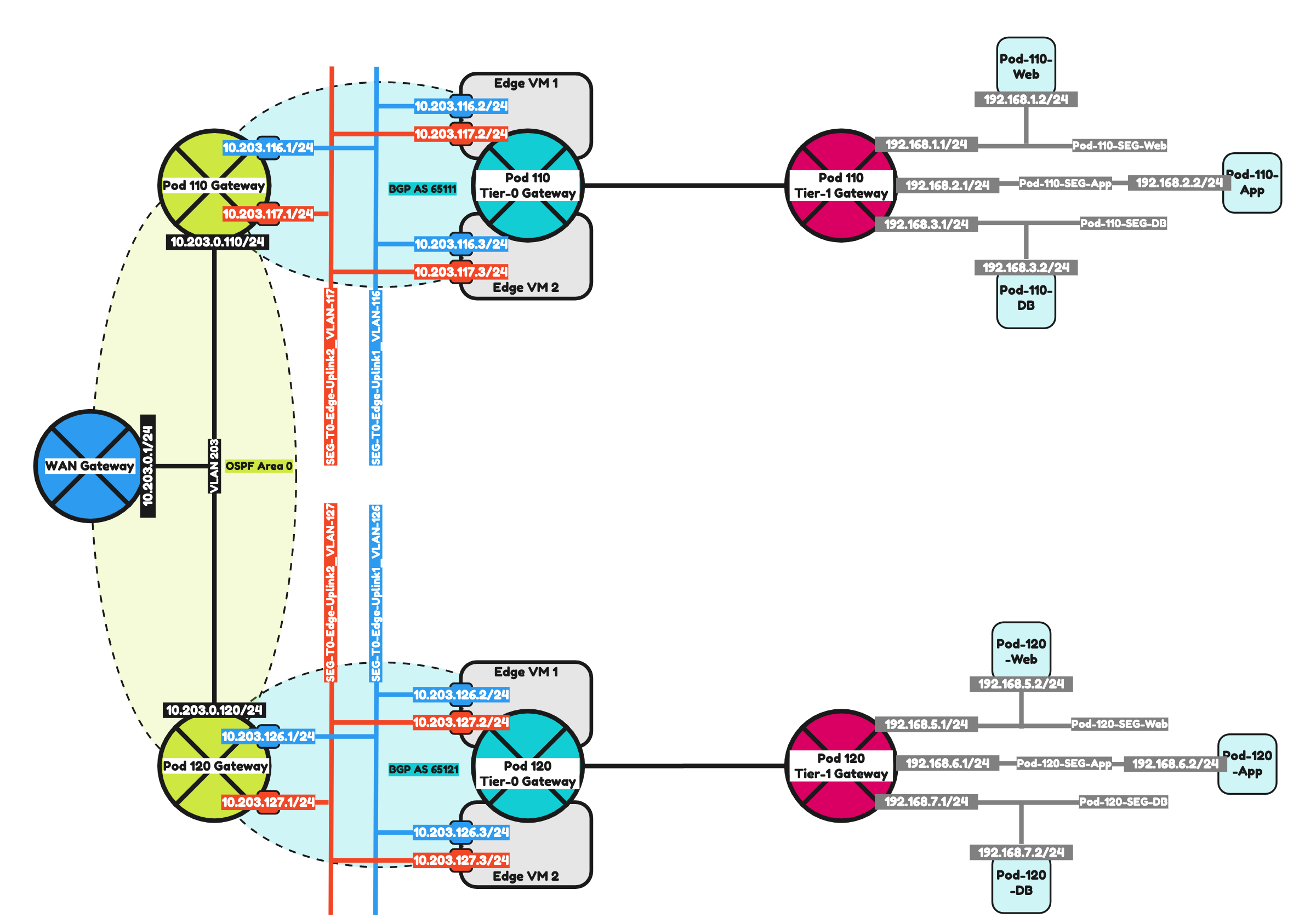
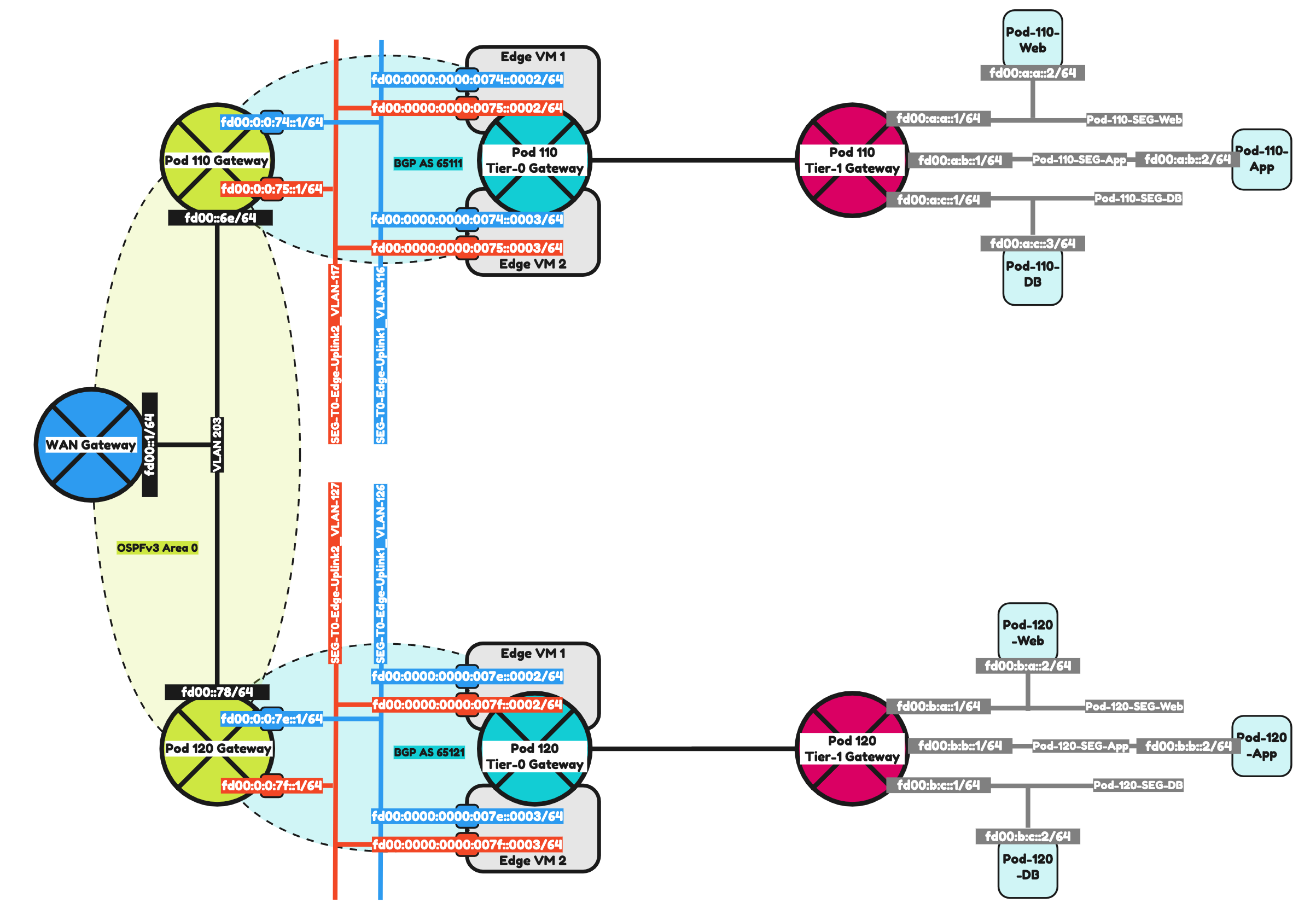
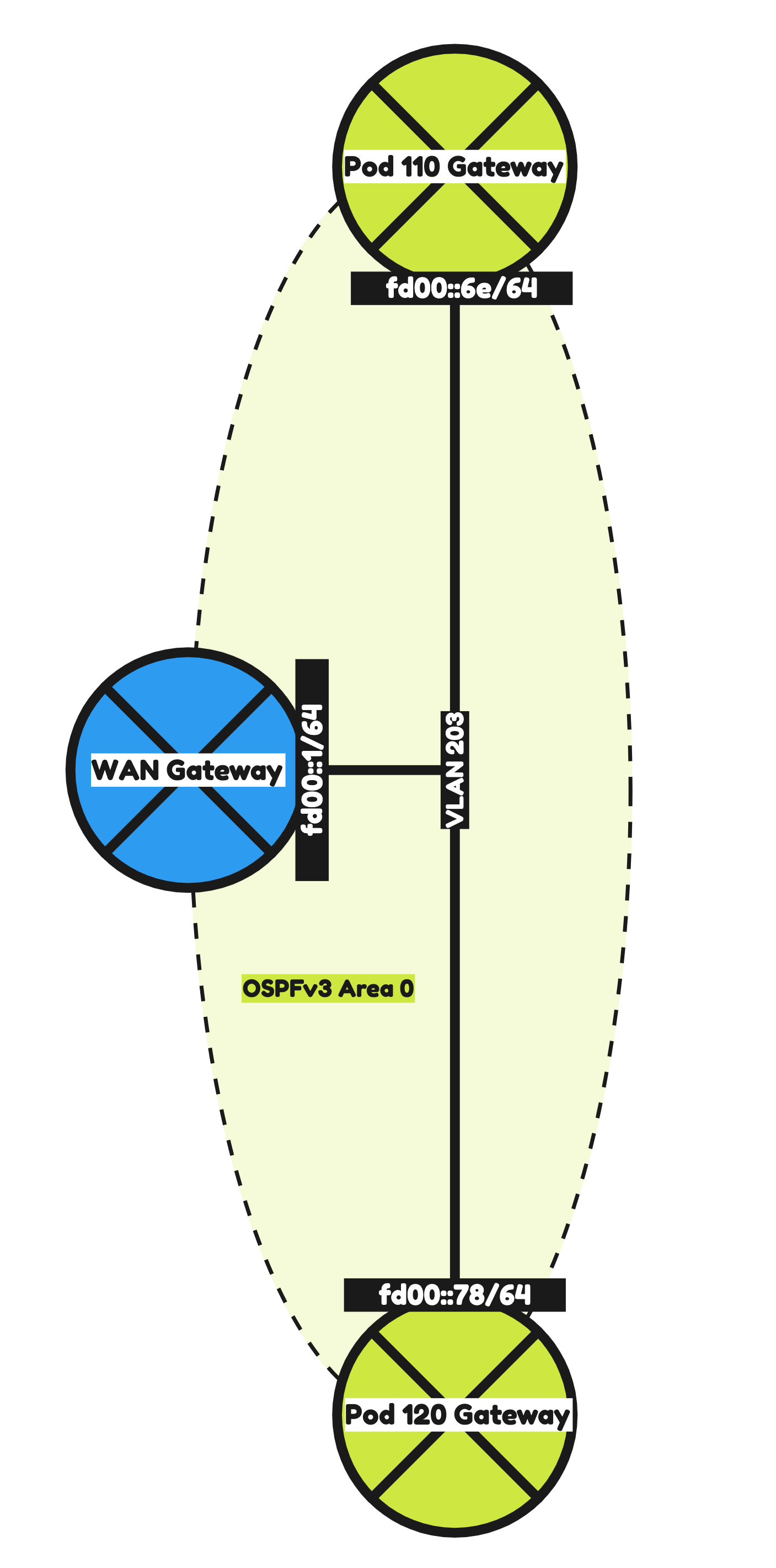
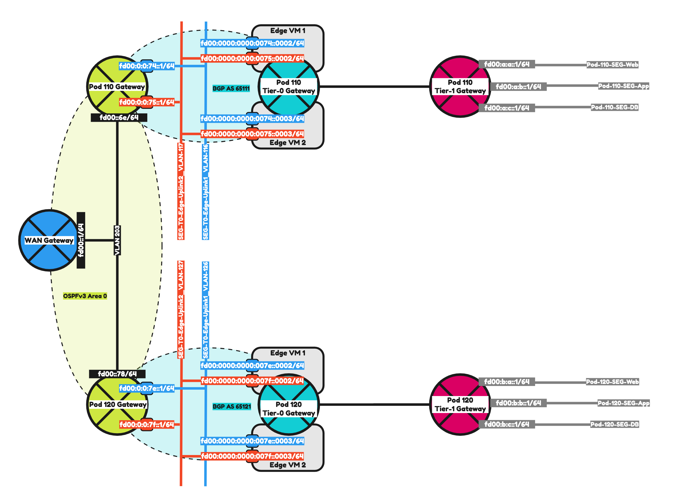
To make it a bit easier to understand I have included two network diagrams below. One with the IPv4 address details and one with the IPv6 address details. I will be using the IPv6 address details moving forward.
The Steps
- STEP 1: Configure IPv6 Routing using OSPFv3 on the WAN Gateway
- STEP 2: Configure IPv6 Routing using OSPFv3 between the WAN Gateway and the Pod Gateway
- STEP 3: Prepare Pod Gateways for IPv6 BGP
- STEP 4: Add IPv6 BGP Uplink Segments in NSX
- STEP 5: Create a Tier-0 Gateway
- STEP 6: Configure IPv6 BGP Routing between Tier-0 Gateway and the Pod Gateway
- STEP 7: Create a Tier-1 Gateway
- STEP 8: Add IPv6 Web, App and DB Segments in NSX
- STEP 9: Configure Route Advertise connected Tier-1 Gateway segment networks to BGP
- STEP 10: Configure route redistribution between BGP and OSPFv3
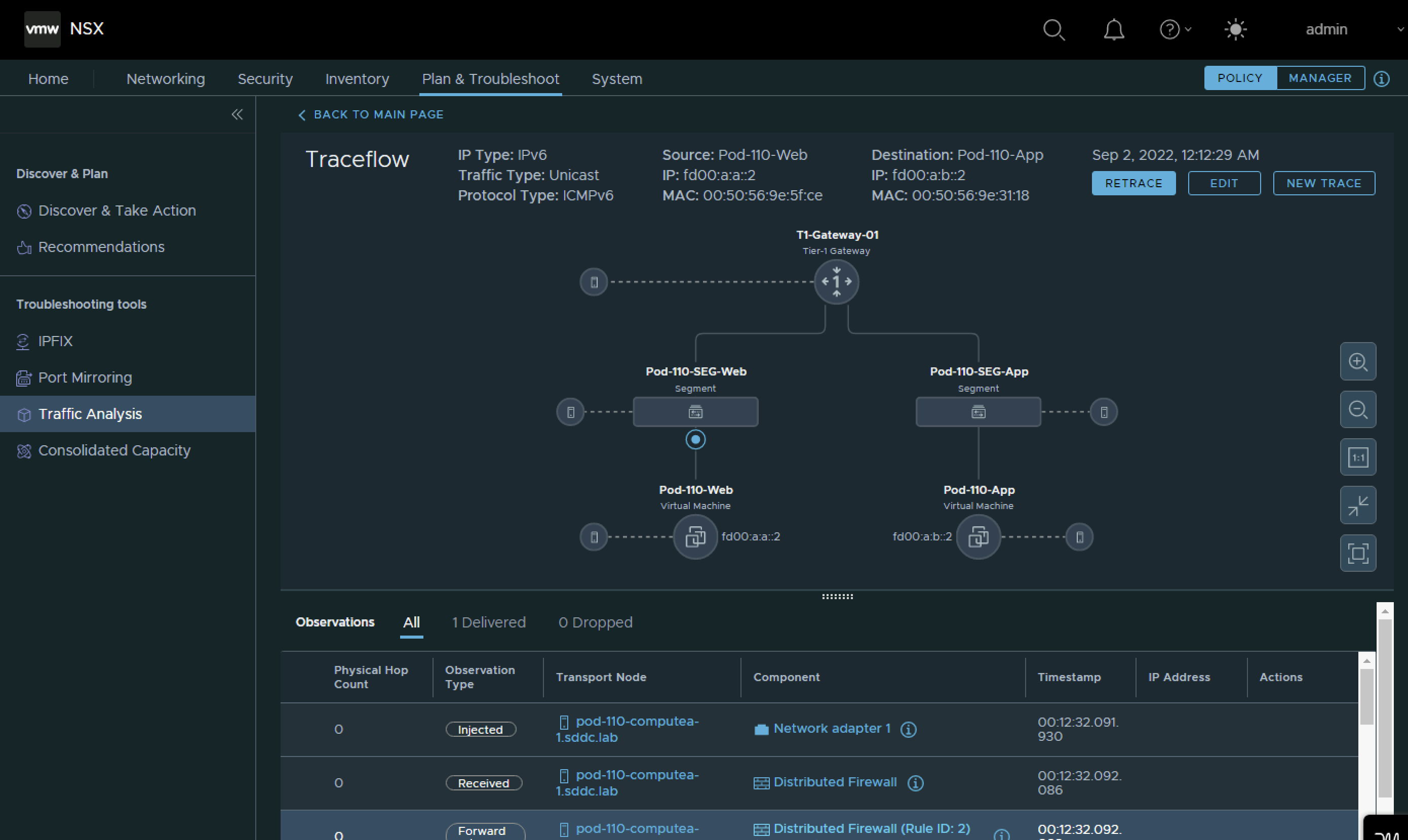
- STEP 11: Create Test Virtual Machines and perform ping connectivity tests
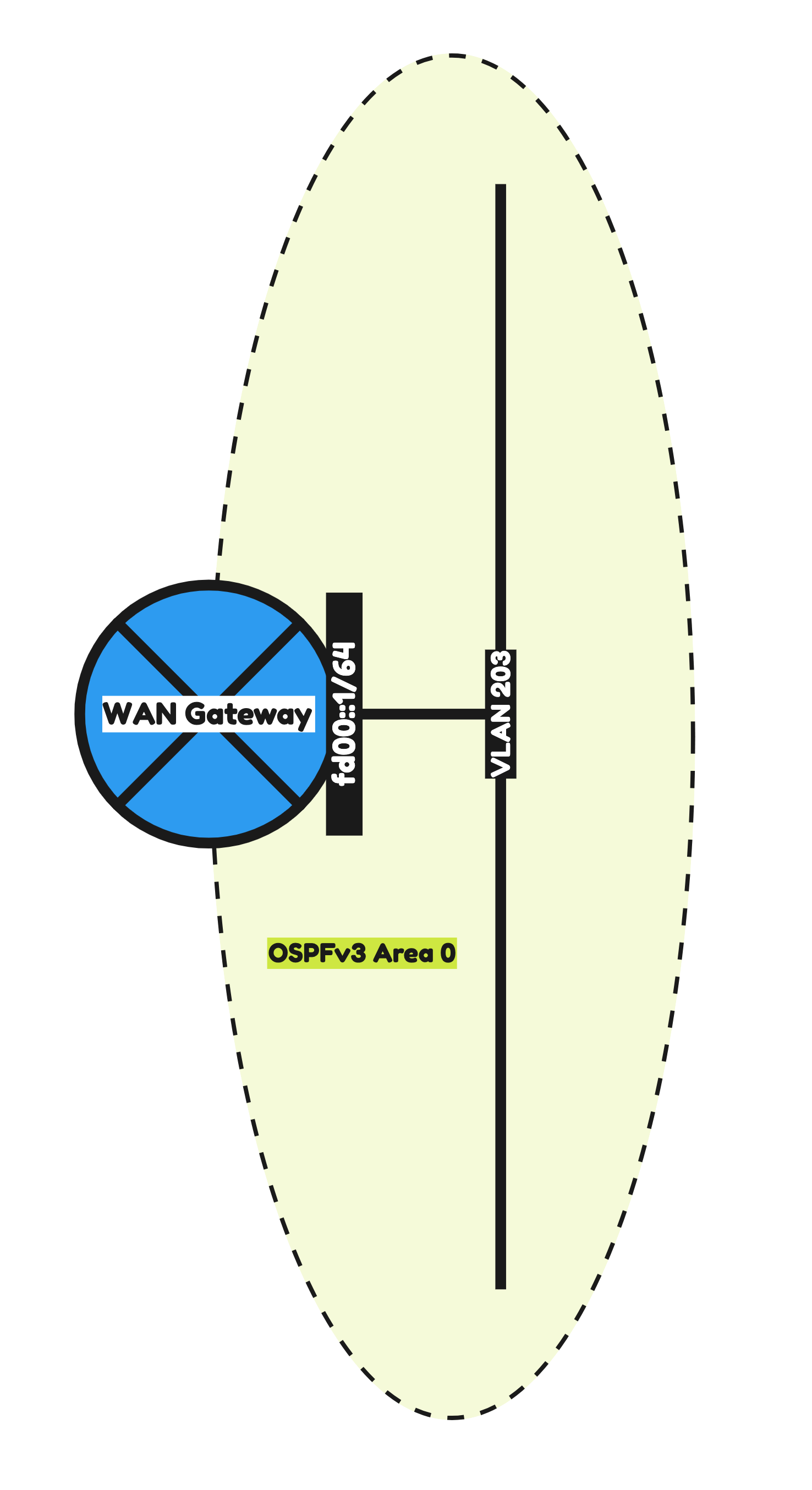
STEP 1» Configure IPv6 Routing using OSPFv3 on the WAN Gateway
The first step in this lab is to make sure OSPFv3 is configured in the WAN Gateway so that it can exchange IPv6 networks with the Pod-110 and Pod-120 Routers.
The configuration parameters that I will used are listed in the table below.
| Hardware | Ubiquiti Networks Edge Router 4 |
|---|---|
| Hostname | WAN-Gateway |
| Domain Name | sddc.lab |
| DNS Server | 10.203.0.5 |
| VLAN 203 IP Address | 10.203.0.1/24 |
| VLAN 203 IPv6 Address | fd00::1/64 |
| OSPF Area | 0 |
| OSPF dead timer | 40 |
| OSPF hello timer | 10 |
| OSPFv3 Area | 0.0.0.0 |
The commands that I am using to configure the WAN Gateway can be found below.
configure
#
set system domain-name sddc.lab
set system host-name WAN-Gateway
set system name-server 10.203.0.5
#
set service ssh port 22
set service ssh protocol-version v2
#
set interfaces ethernet eth1 description 'eth1 - LAN'
set interfaces ethernet eth1 duplex auto
set interfaces ethernet eth1 mtu 9000
set interfaces ethernet eth1 speed auto
#
set interfaces ethernet eth1 vif 203 description 'Router Uplink'
set interfaces ethernet eth1 vif 203 address 10.203.0.1/24
set interfaces ethernet eth1 vif 203 address 'fd00::1/64'
set interfaces ethernet eth1 vif 203 ip ospf dead-interval 40
set interfaces ethernet eth1 vif 203 ip ospf hello-interval 10
set interfaces ethernet eth1 vif 203 ip ospf priority 1
set interfaces ethernet eth1 vif 203 ip ospf retransmit-interval 5
set interfaces ethernet eth1 vif 203 ip ospf transmit-delay 1
set interfaces ethernet eth1 vif 203 mtu 1500
#
set interfaces ethernet eth1 vif 203 ipv6 dup-addr-detect-transmits 1
set interfaces ethernet eth1 vif 203 ipv6 router-advert cur-hop-limit 64
set interfaces ethernet eth1 vif 203 ipv6 router-advert link-mtu 0
set interfaces ethernet eth1 vif 203 ipv6 router-advert managed-flag false
set interfaces ethernet eth1 vif 203 ipv6 router-advert max-interval 600
set interfaces ethernet eth1 vif 203 ipv6 router-advert other-config-flag false
set interfaces ethernet eth1 vif 203 ipv6 router-advert prefix 'fd00::/64' autonomous-flag true
set interfaces ethernet eth1 vif 203 ipv6 router-advert prefix 'fd00::/64' on-link-flag true
set interfaces ethernet eth1 vif 203 ipv6 router-advert prefix 'fd00::/64' valid-lifetime 2592000
set interfaces ethernet eth1 vif 203 ipv6 router-advert reachable-time 0
set interfaces ethernet eth1 vif 203 ipv6 router-advert retrans-timer 0
set interfaces ethernet eth1 vif 203 ipv6 router-advert send-advert true
#
set protocols ospf area 0 area-type normal
set protocols ospf area 0 network 10.203.0.0/24
set protocols ospf parameters abr-type cisco
set protocols ospf parameters router-id 10.203.0.1
set protocols ospf redistribute connected metric-type 2
#
set protocols ospfv3 area 0.0.0.0 area-type normal
set protocols ospfv3 area 0.0.0.0 interface eth1.203
set protocols ospfv3 area 0.0.0.0 range 'fd00::/64'
set protocols ospfv3 parameters abr-type cisco
set protocols ospfv3 parameters router-id 10.203.0.1
set protocols ospfv3 redistribute connected
#
commit
save
OSPF Verification
After the configuration of the WAN Gateway I did a quick verification to see if I could see any OSPFv3 neighbors.
admin@WAN-Gateway:~$ show ip ospf neighbor
admin@WAN-Gateway:~$
Because my Pod Routers are not configured yet with OSPFv3 I am not able to see the neighbors yet. I will do this configuration in the next step.
STEP 2» Configure IPv6 Routing using OSPFv3 between the WAN Gateway and the Pod Gateways
Now that the WAN Gateway is fully configured with OSPFv3 I am going to configure the Pod Routers with OSPFv3 so that the WAN gateway and the Pod Routers can form a neighbor relationship to exchange IPv6 routes.
Pod 110
The configuration parameters that I will use for Pod-110 are listed in the table below.
| Software | VyOS |
|---|---|
| Hostname | Pod-110-Router |
| Domain Name | sddc.lab |
| DNS/NTP Server (IPv4) | 10.203.0.5 |
| DNS/NTP Server (IPv6) | fd00:0000:0000:0000::0005 |
| VLAN 203 IPv4 Address | 10.203.0.110/24 |
| VLAN 203 IPv6 Address | fd00:0000:0000:0000::006e/64 |
| OSPF Area | 0 |
| OSPF dead timer | 40 |
| OSPF hello timer | 10 |
| OSPFv3 Area | 0.0.0.0 |
I also decided to configure some additional interfaces so that these networks can be redistributed into OSPF.
The configuration parameters for these interfaces ale listed in the table below.
| VLAN | IPv4 address | IPv6 address | |
|---|---|---|---|
| Management VLAN Pod 110 | 110 | 10.203.110.1/24 | fd00:0000:0000:006e::0001/64 |
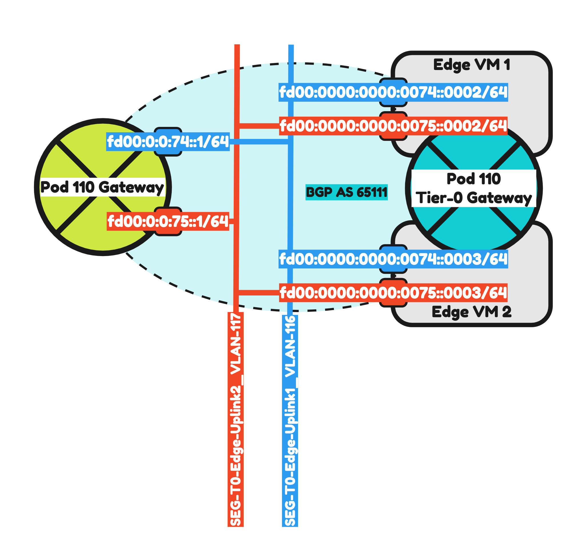
| BGP Uplink VLAN #1 Pod 110 | 116 | 10.203.116.1/24 | fd00:0000:0000:0074::0001/64 |
| BGP Uplink VLAN #2 Pod 110 | 117 | 10.203.117.1/24 | fd00:0000:0000:0075::0001/64 |
The commands that I am using to configure the Pod-110 Router can be found below.
configure
#
set system domain-name sddc.lab
set system host-name 'Pod-110-Router'
set system name-server '10.203.0.5'
set system name-server 'fd00:0000:0000:0000::0005'
#
set service ssh port 22
set service ssh protocol-version v2
#
set interfaces ethernet eth0 address '10.203.0.110/24'
set interfaces ethernet eth0 address 'fd00:0000:0000:0000::006e/64'
set interfaces ethernet eth0 description 'Router Uplink'
set interfaces ethernet eth0 mtu '1500'
#
set interfaces ethernet eth1 mtu '9000'
set interfaces ethernet eth1 vif 110 address '10.203.110.1/24'
set interfaces ethernet eth1 vif 110 address 'fd00:0000:0000:006e::0001/64'
set interfaces ethernet eth1 vif 110 description 'Management'
set interfaces ethernet eth1 vif 110 mtu '1500'
#
set interfaces ethernet eth1 vif 116 address '10.203.116.1/24'
set interfaces ethernet eth1 vif 116 address 'fd00:0000:0000:0074::0001/64'
set interfaces ethernet eth1 vif 116 description 'NSX Edge Uplink #1'
set interfaces ethernet eth1 vif 116 mtu '1500'
set interfaces ethernet eth1 vif 117 address '10.203.117.1/24'
set interfaces ethernet eth1 vif 117 address 'fd00:0000:0000:0075::0001/64'
set interfaces ethernet eth1 vif 117 description 'NSX Edge Uplink #2'
set interfaces ethernet eth1 vif 117 mtu '1500'
#
set protocols ospf area 0 network '10.203.0.0/24'
set protocols ospf area 110 area-type normal
set protocols ospf area 110 network '10.203.116.0/24'
set protocols ospf area 110 network '10.203.117.0/24'
set protocols ospf log-adjacency-changes
set protocols ospf parameters router-id '10.203.0.110'
set protocols ospf redistribute connected metric-type '2'
set protocols ospfv3 interface eth0 area '0.0.0.0'
set protocols ospfv3 parameters router-id '10.203.0.110'
set protocols ospfv3 redistribute connected
#
set protocols static route 0.0.0.0/0 next-hop 10.203.0.1 distance '250'
#
set service router-advert interface eth0 prefix fd00::/64
set service router-advert interface eth1.110 prefix fd00:0:0:6e::/64
set service router-advert interface eth1.116 prefix fd00:0:0:74::/64
set service router-advert interface eth1.117 prefix fd00:0:0:75::/64
#
set system ntp listen-address '10.203.110.1'
set system ntp server 10.203.0.5
set system ntp server fd00:0000:0000:0000::0005
#
commit
save
Pod 120
The configuration parameters that I will use for Pod-110 are listed in the table below.
| Software | VyOS |
|---|---|
| Hostname | Pod-120-Router |
| Domain Name | sddc.lab |
| DNS/NTP Server (IPv4) | 10.203.0.5 |
| DNS/NTP Server (IPv6) | fd00:0000:0000:0000::0005 |
| VLAN 203 IP Address | 10.203.0.120/24 |
| VLAN 203 IPv6 Address | fd00:0000:0000:0000::0078/64 |
| OSPF Area | 0 |
| OSPF dead timer | 40 |
| OSPF hello timer | 10 |
| OSPFv3 Area | 0.0.0.0 |
I also decided to configure some additional interfaces so that these networks can be redistributed into OSPF.
The configuration parameters for these interfaces ale listed in the table below.
| VLAN | IPv4 address | IPv6 address | |
|---|---|---|---|
| Management VLAN Pod 120 | 120 | 10.203.120.1/24 | fd00:0000:0000:0078::0001/64 |
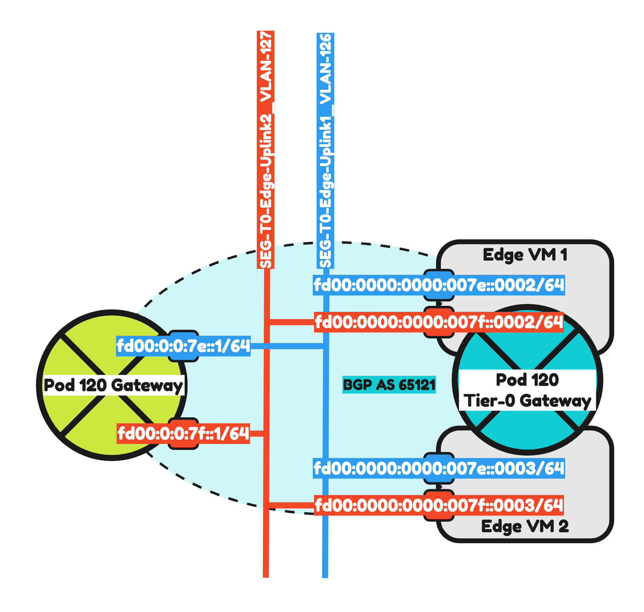
| BGP Uplink VLAN #1 Pod 120 | 126 | 10.203.126.1/24 | fd00:0000:0000:007e::0001/64 |
| BGP Uplink VLAN #2 Pod 120 | 127 | 10.203.127.1/24 | fd00:0000:0000:007f::0001/64 |
The commands that I am using to configure the Pod-110 Router can be found below.
configure
#
set system domain-name sddc.lab
set system host-name 'Pod-120-Router'
set system name-server '10.203.0.5'
set system name-server 'fd00:0000:0000:0000::0005'
#
set service ssh port 22
set service ssh protocol-version v2
#
set interfaces ethernet eth0 address '10.203.0.120/24'
set interfaces ethernet eth0 address 'fd00:0000:0000:0000::0078/64'
set interfaces ethernet eth0 description 'Router Uplink'
set interfaces ethernet eth0 mtu '1500'
#
set interfaces ethernet eth1 mtu '9000'
set interfaces ethernet eth1 vif 120 address '10.203.120.1/24'
set interfaces ethernet eth1 vif 120 address 'fd00:0000:0000:0078::0001/64'
set interfaces ethernet eth1 vif 120 description 'Management'
set interfaces ethernet eth1 vif 120 mtu '1500'
#
set interfaces ethernet eth1 vif 126 address '10.203.126.1/24'
set interfaces ethernet eth1 vif 126 address 'fd00:0000:0000:007e::0001/64'
set interfaces ethernet eth1 vif 126 description 'NSX Edge Uplink #1'
set interfaces ethernet eth1 vif 126 mtu '1500'
#
set interfaces ethernet eth1 vif 127 address '10.203.127.1/24'
set interfaces ethernet eth1 vif 127 address 'fd00:0000:0000:007f::0001/64'
set interfaces ethernet eth1 vif 127 description 'NSX Edge Uplink #2'
set interfaces ethernet eth1 vif 127 mtu '1500'
#
set protocols ospf area 0 network '10.203.0.0/24'
set protocols ospf area 120 area-type normal
set protocols ospf area 120 network '10.203.126.0/24'
set protocols ospf area 120 network '10.203.127.0/24'
set protocols ospf log-adjacency-changes
set protocols ospf parameters router-id '10.203.0.120'
set protocols ospf redistribute connected metric-type '2'
set protocols ospfv3 interface eth0 area '0.0.0.0'
set protocols ospfv3 parameters router-id '10.203.0.120'
set protocols ospfv3 redistribute connected
#
set protocols static route 0.0.0.0/0 next-hop 10.203.0.1 distance '250'
#
set service router-advert interface eth0 prefix fd00::/64
set service router-advert interface eth1.120 prefix fd00:0:0:78::/64
set service router-advert interface eth1.126 prefix fd00:0:0:7e::/64
set service router-advert interface eth1.127 prefix fd00:0:0:7f::/64
#
set system ntp listen-address '10.203.120.1'
set system ntp server 10.203.0.5
set system ntp server fd00:0000:0000:0000::0005
#
commit
save
OSPF Verification
Now that OSPFv3 is configured between the WAN Gateway and the Pod Routers I can now verify if there is a neighbor adjacency formed.
On the WAN Gateway I see two neighbors that are the Pod Routers.
admin@WAN-Gateway:~$ show ipv6 ospfv3 neighbor
OSPFv3 Process (*null*)
Neighbor ID     Pri   State           Dead Time   Interface  Instance ID
10.203.0.110      1   Full/DR         00:00:31    eth1.203   0
10.203.0.120      1   Full/Backup     00:00:35    eth1.203   0
ubnt@ubnt:~$
On the Pod-110 Router I also have two neighbors.
vyos@Pod-110-Router:~$ show ipv6 ospfv3 neighbor
Neighbor ID     Pri    DeadTime    State/IfState         Duration I/F[State]
10.203.0.1        1    00:00:38     Full/DROther       5d11:01:06 eth0[DR]
10.203.0.120      1    00:00:32     Full/BDR           5d17:25:40 eth0[DR]
vyos@Pod-110-Router:~$
On the Pod-120 Router I also have two neighbors.
vyos@Pod-120-Router:~$ show ipv6 ospfv3 neighbor
Neighbor ID     Pri    DeadTime    State/IfState         Duration I/F[State]
10.203.0.1        1    00:00:30     Full/DROther       5d11:02:16 eth0[BDR]
10.203.0.110      1    00:00:32     Full/DR            5d17:26:56 eth0[BDR]
vyos@Pod-120-Router:~$
STEP 3» Prepare Pod Gateways for IPv6 BGP
Now that OSPFv3 os working I am now going to prepare IPv6 BGP on the Pod Routers so that it will be able to peer with the Pod Tier-0 Gateways.
Pod 110
I have already configured the BGP uplink VLANs and interfaces in the previous step.
So now it is time to configured IPv6 BGP on Pod-110 using the configuration parameters in the table below
| Neigbor | Local AS | Remote AS | Peer IPv4 | Peer IPv6 |
|---|---|---|---|---|
| WAN Gateway | 65110 | 65000 | 10.203.0.1 | fd00:0000:0000:0000::0001 |
| Pod-110-T0-EdgeVM-01-1 | 65110 | 65111 | 10.203.116.2 | fd00:0000:0000:0074::0002 |
| Pod-110-T0-EdgeVM-02-1 | 65110 | 65111 | 10.203.116.3 | fd00:0000:0000:0074::0003 |
| Pod-110-T0-EdgeVM-01-2 | 65110 | 65111 | 10.203.117.2 | fd00:0000:0000:0075::0002 |
| Pod-110-T0-EdgeVM-02-2 | 65110 | 65111 | 10.203.117.3 | fd00:0000:0000:0075::0003 |
The commands that I am using to configure the Pod-110 Router can be found below.
set protocols bgp local-as '65110'
set protocols bgp neighbor 10.203.0.1 address-family ipv4-unicast
set protocols bgp neighbor 10.203.0.1 description 'Lab-Router'
set protocols bgp neighbor 10.203.0.1 remote-as '65000'
set protocols bgp neighbor 10.203.116.2 address-family ipv4-unicast default-originate
set protocols bgp neighbor 10.203.116.2 description 'Pod-110-T0-EdgeVM-01-1'
set protocols bgp neighbor 10.203.116.2 remote-as '65111'
set protocols bgp neighbor 10.203.116.3 address-family ipv4-unicast default-originate
set protocols bgp neighbor 10.203.116.3 description 'Pod-110-T0-EdgeVM-02-1'
set protocols bgp neighbor 10.203.116.3 remote-as '65111'
set protocols bgp neighbor 10.203.117.2 address-family ipv4-unicast default-originate
set protocols bgp neighbor 10.203.117.2 description 'Pod-110-T0-EdgeVM-01-2'
set protocols bgp neighbor 10.203.117.2 remote-as '65111'
set protocols bgp neighbor 10.203.117.3 address-family ipv4-unicast default-originate
set protocols bgp neighbor 10.203.117.3 description 'Pod-110-T0-EdgeVM-02-2'
set protocols bgp neighbor 10.203.117.3 remote-as '65111'
set protocols bgp neighbor fd00:0000:0000:0000::0001 address-family ipv6-unicast
set protocols bgp neighbor fd00:0000:0000:0000::0001 description 'Lab-Router'
set protocols bgp neighbor fd00:0000:0000:0000::0001 remote-as '65000'
set protocols bgp neighbor fd00:0000:0000:0074::0002 address-family ipv6-unicast default-originate
set protocols bgp neighbor fd00:0000:0000:0074::0002 description 'Pod-110-T0-EdgeVM-01-1'
set protocols bgp neighbor fd00:0000:0000:0074::0002 remote-as '65111'
set protocols bgp neighbor fd00:0000:0000:0074::0003 address-family ipv6-unicast default-originate
set protocols bgp neighbor fd00:0000:0000:0074::0003 description 'Pod-110-T0-EdgeVM-02-1'
set protocols bgp neighbor fd00:0000:0000:0074::0003 remote-as '65111'
set protocols bgp neighbor fd00:0000:0000:0075::0002 address-family ipv6-unicast default-originate
set protocols bgp neighbor fd00:0000:0000:0075::0002 description 'Pod-110-T0-EdgeVM-01-2'
set protocols bgp neighbor fd00:0000:0000:0075::0002 remote-as '65111'
set protocols bgp neighbor fd00:0000:0000:0075::0003 address-family ipv6-unicast default-originate
set protocols bgp neighbor fd00:0000:0000:0075::0003 description 'Pod-110-T0-EdgeVM-02-2'
set protocols bgp neighbor fd00:0000:0000:0075::0003 remote-as '65111'
set protocols bgp parameters router-id '10.203.110.1'
#
To make the SDDC Network configuration complete I have also added the VLANs and interfaces based on the table below.
| VLAN | IPv4 Address | IPv6 Address | |
|---|---|---|---|
| vMotion | 111 | 10.203.111.1/24 | fd00:0000:0000:006f::0001/64 |
| vSAN | 112 | 10.203.112.1/24 | fd00:0000:0000:0070::0001/64 |
| IP Storage | 113 | 10.203.113.1/24 | fd00:0000:0000:0071::0001/64 |
| Overlay Transport | 114 | 10.203.114.1/24 | fd00:0000:0000:0072::0001/64 |
| Service VM Management | 115 | 10.203.115.1/24 | fd00:0000:0000:0073::0001/64 |
| RTEP Transport | 118 | 10.203.118.1/24 | fd00:0000:0000:0076::0001/64 |
The commands that I am using to configure the Pod-110 Router can be found below.
set interfaces ethernet eth1 vif 111 address '10.203.111.1/24'
set interfaces ethernet eth1 vif 111 address 'fd00:0000:0000:006f::0001/64'
set interfaces ethernet eth1 vif 111 description 'vMotion'
set interfaces ethernet eth1 vif 111 mtu '9000'
set interfaces ethernet eth1 vif 112 address '10.203.112.1/24'
set interfaces ethernet eth1 vif 112 address 'fd00:0000:0000:0070::0001/64'
set interfaces ethernet eth1 vif 112 description 'vSAN'
set interfaces ethernet eth1 vif 112 mtu '9000'
set interfaces ethernet eth1 vif 113 address '10.203.113.1/24'
set interfaces ethernet eth1 vif 113 address 'fd00:0000:0000:0071::0001/64'
set interfaces ethernet eth1 vif 113 description 'IP Storage'
set interfaces ethernet eth1 vif 113 mtu '9000'
set interfaces ethernet eth1 vif 114 address '10.203.114.1/24'
set interfaces ethernet eth1 vif 114 address 'fd00:0000:0000:0072::0001/64'
set interfaces ethernet eth1 vif 114 description 'Overlay Transport'
set interfaces ethernet eth1 vif 114 mtu '9000'
set interfaces ethernet eth1 vif 115 address '10.203.115.1/24'
set interfaces ethernet eth1 vif 115 address 'fd00:0000:0000:0073::0001/64'
set interfaces ethernet eth1 vif 115 description 'Service VM Management'
set interfaces ethernet eth1 vif 115 mtu '1500'
set interfaces ethernet eth1 vif 118 address '10.203.118.1/24'
set interfaces ethernet eth1 vif 118 address 'fd00:0000:0000:0076::0001/64'
set interfaces ethernet eth1 vif 118 description 'RTEP Transport'
set interfaces ethernet eth1 vif 118 mtu '1500'
set interfaces loopback lo
#
set service router-advert interface eth1.111 prefix fd00:0:0:6f::/64
set service router-advert interface eth1.112 prefix fd00:0:0:70::/64
set service router-advert interface eth1.113 prefix fd00:0:0:71::/64
set service router-advert interface eth1.114 prefix fd00:0:0:72::/64
set service router-advert interface eth1.115 prefix fd00:0:0:73::/64
set service router-advert interface eth1.118 prefix fd00:0:0:76::/64
#
Because the Pod-110 Tier-0 Gateway is not configured yet, I do not see any BGP neighbors (output not included). This will be configured in Step 4.
Pod 120
I have already configured the BGP uplink VLANs and interfaces in the previous step.
So now it is time to configured IPv6 BGP on Pod-120 using the configuration parameters in the table below
| Neigbor | Local AS | Remote AS | Peer IPv4 | Peer IPv6 |
|---|---|---|---|---|
| WAN Gateway | 65120 | 65000 | 10.203.0.1 | fd00:0000:0000:0000::0001 |
| Pod-110-T0-EdgeVM-01-1 | 65120 | 65121 | 10.203.126.2 | fd00:0000:0000:007e::0002 |
| Pod-110-T0-EdgeVM-02-1 | 65120 | 65121 | 10.203.126.3 | fd00:0000:0000:007e::0003 |
| Pod-110-T0-EdgeVM-01-2 | 65120 | 65121 | 10.203.127.2 | fd00:0000:0000:007f::0002 |
| Pod-110-T0-EdgeVM-02-2 | 65120 | 65121 | 10.203.127.3 | fd00:0000:0000:007f::0003 |
The commands that I am using to configure the Pod-110 Router can be found below.
set protocols bgp local-as '65120'
set protocols bgp neighbor 10.203.0.1 address-family ipv4-unicast
set protocols bgp neighbor 10.203.0.1 description 'Lab-Router'
set protocols bgp neighbor 10.203.0.1 remote-as '65000'
set protocols bgp neighbor 10.203.126.2 address-family ipv4-unicast default-originate
set protocols bgp neighbor 10.203.126.2 description 'Pod-120-T0-EdgeVM-01-1'
set protocols bgp neighbor 10.203.126.2 remote-as '65121'
set protocols bgp neighbor 10.203.126.3 address-family ipv4-unicast default-originate
set protocols bgp neighbor 10.203.126.3 description 'Pod-120-T0-EdgeVM-02-1'
set protocols bgp neighbor 10.203.126.3 remote-as '65121'
set protocols bgp neighbor 10.203.127.2 address-family ipv4-unicast default-originate
set protocols bgp neighbor 10.203.127.2 description 'Pod-120-T0-EdgeVM-01-2'
set protocols bgp neighbor 10.203.127.2 remote-as '65121'
set protocols bgp neighbor 10.203.127.3 address-family ipv4-unicast default-originate
set protocols bgp neighbor 10.203.127.3 description 'Pod-120-T0-EdgeVM-02-2'
set protocols bgp neighbor 10.203.127.3 remote-as '65121'
set protocols bgp neighbor fd00:0000:0000:0000::0001 address-family ipv6-unicast
set protocols bgp neighbor fd00:0000:0000:0000::0001 description 'Lab-Router'
set protocols bgp neighbor fd00:0000:0000:0000::0001 remote-as '65000'
set protocols bgp neighbor fd00:0000:0000:007e::0002 address-family ipv6-unicast default-originate
set protocols bgp neighbor fd00:0000:0000:007e::0002 description 'Pod-120-T0-EdgeVM-01-1'
set protocols bgp neighbor fd00:0000:0000:007e::0002 remote-as '65121'
set protocols bgp neighbor fd00:0000:0000:007e::0003 address-family ipv6-unicast default-originate
set protocols bgp neighbor fd00:0000:0000:007e::0003 description 'Pod-120-T0-EdgeVM-02-1'
set protocols bgp neighbor fd00:0000:0000:007e::0003 remote-as '65121'
set protocols bgp neighbor fd00:0000:0000:007f::0002 address-family ipv6-unicast default-originate
set protocols bgp neighbor fd00:0000:0000:007f::0002 description 'Pod-120-T0-EdgeVM-01-2'
set protocols bgp neighbor fd00:0000:0000:007f::0002 remote-as '65121'
set protocols bgp neighbor fd00:0000:0000:007f::0003 address-family ipv6-unicast default-originate
set protocols bgp neighbor fd00:0000:0000:007f::0003 description 'Pod-120-T0-EdgeVM-02-2'
set protocols bgp neighbor fd00:0000:0000:007f::0003 remote-as '65121'
set protocols bgp parameters router-id '10.203.120.1'
#
To make the SDDC Network configuration complete I have also added the VLANs and interfaces based on the table below.
| VLAN | IPv4 Address | IPv6 Address | |
|---|---|---|---|
| vMotion | 121 | 10.203.121.1/24 | fd00:0000:0000:0079::0001/64 |
| vSAN | 122 | 10.203.122.1/24 | fd00:0000:0000:007a::0001/64 |
| IP Storage | 123 | 10.203.123.1/24 | fd00:0000:0000:007b::0001/64 |
| Overlay Transport | 124 | 10.203.124.1/24 | fd00:0000:0000:007c::0001/64 |
| Service VM Management | 125 | 10.203.125.1/24 | fd00:0000:0000:007d::0001/64 |
| RTEP Transport | 128 | 10.203.128.1/24 | fd00:0000:0000:0080::0001/64 |
The commands that I am using to configure the Pod-110 Router can be found below.
set interfaces ethernet eth1 vif 121 address '10.203.121.1/24'
set interfaces ethernet eth1 vif 121 address 'fd00:0000:0000:0079::0001/64'
set interfaces ethernet eth1 vif 121 description 'vMotion'
set interfaces ethernet eth1 vif 121 mtu '9000'
set interfaces ethernet eth1 vif 122 address '10.203.122.1/24'
set interfaces ethernet eth1 vif 122 address 'fd00:0000:0000:007a::0001/64'
set interfaces ethernet eth1 vif 122 description 'vSAN'
set interfaces ethernet eth1 vif 122 mtu '9000'
set interfaces ethernet eth1 vif 123 address '10.203.123.1/24'
set interfaces ethernet eth1 vif 123 address 'fd00:0000:0000:007b::0001/64'
set interfaces ethernet eth1 vif 123 description 'IP Storage'
set interfaces ethernet eth1 vif 123 mtu '9000'
set interfaces ethernet eth1 vif 124 address '10.203.124.1/24'
set interfaces ethernet eth1 vif 124 address 'fd00:0000:0000:007c::0001/64'
set interfaces ethernet eth1 vif 124 description 'Overlay Transport'
set interfaces ethernet eth1 vif 124 mtu '9000'
set interfaces ethernet eth1 vif 125 address '10.203.125.1/24'
set interfaces ethernet eth1 vif 125 address 'fd00:0000:0000:007d::0001/64'
set interfaces ethernet eth1 vif 125 description 'Service VM Management'
set interfaces ethernet eth1 vif 125 mtu '1500'
set interfaces ethernet eth1 vif 128 address '10.203.128.1/24'
set interfaces ethernet eth1 vif 128 address 'fd00:0000:0000:0080::0001/64'
set interfaces ethernet eth1 vif 128 description 'RTEP Transport'
set interfaces ethernet eth1 vif 128 mtu '1500'
set interfaces loopback lo
#
set service router-advert interface eth1.121 prefix fd00:0:0:79::/64
set service router-advert interface eth1.122 prefix fd00:0:0:7a::/64
set service router-advert interface eth1.123 prefix fd00:0:0:7b::/64
set service router-advert interface eth1.124 prefix fd00:0:0:7c::/64
set service router-advert interface eth1.125 prefix fd00:0:0:7d::/64
set service router-advert interface eth1.128 prefix fd00:0:0:80::/64
#
Because the Pod-120 Tier-0 Gateway is not configured yet, I do not see any BGP neighbors (output not included). This will be configured in Step 4.
STEP 4» Add IPv6 BGP Uplink Segments in NSX
The Tier-0 Gateway is using NSX Segments as the main way of communicating with the Physical network. These segments are created inside NSX.
Pod 110
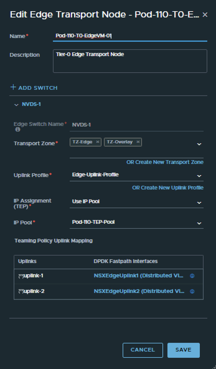
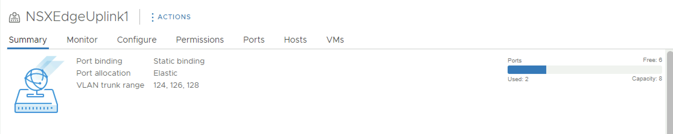
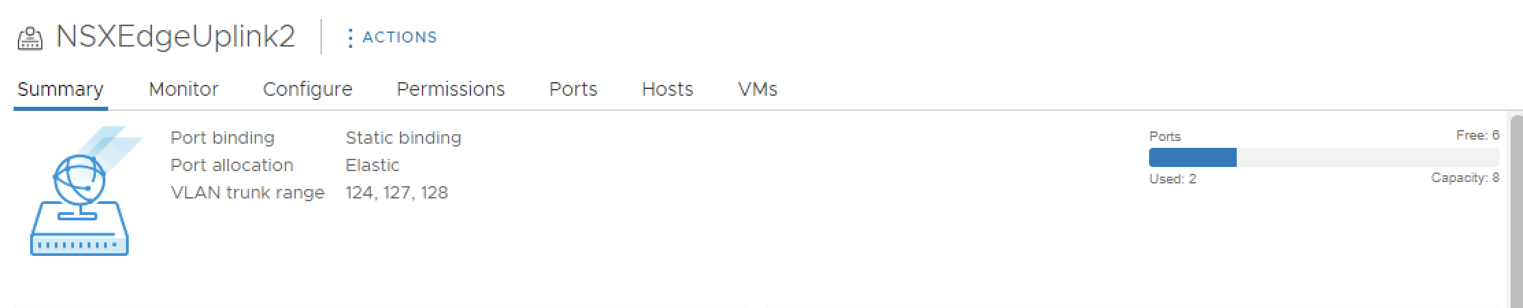
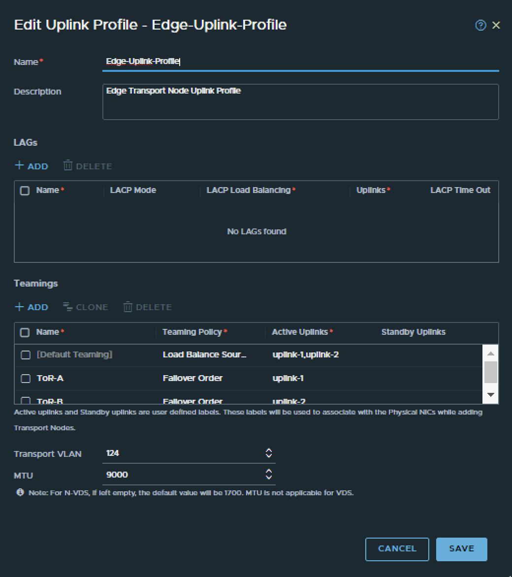
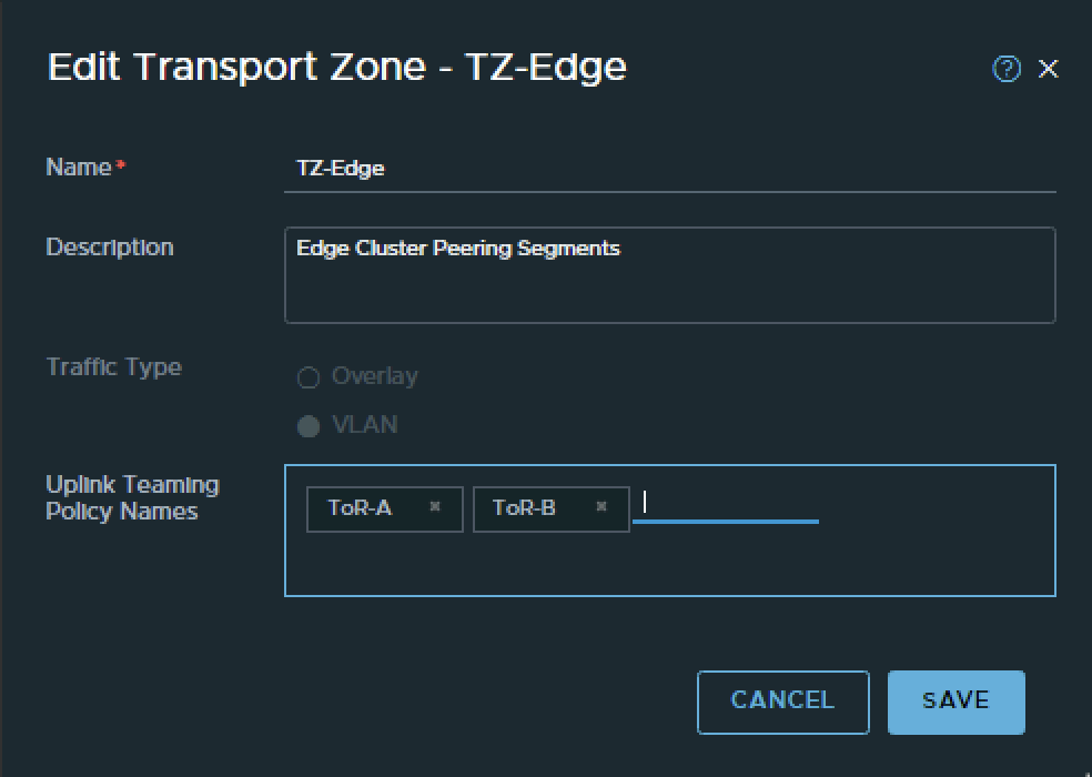
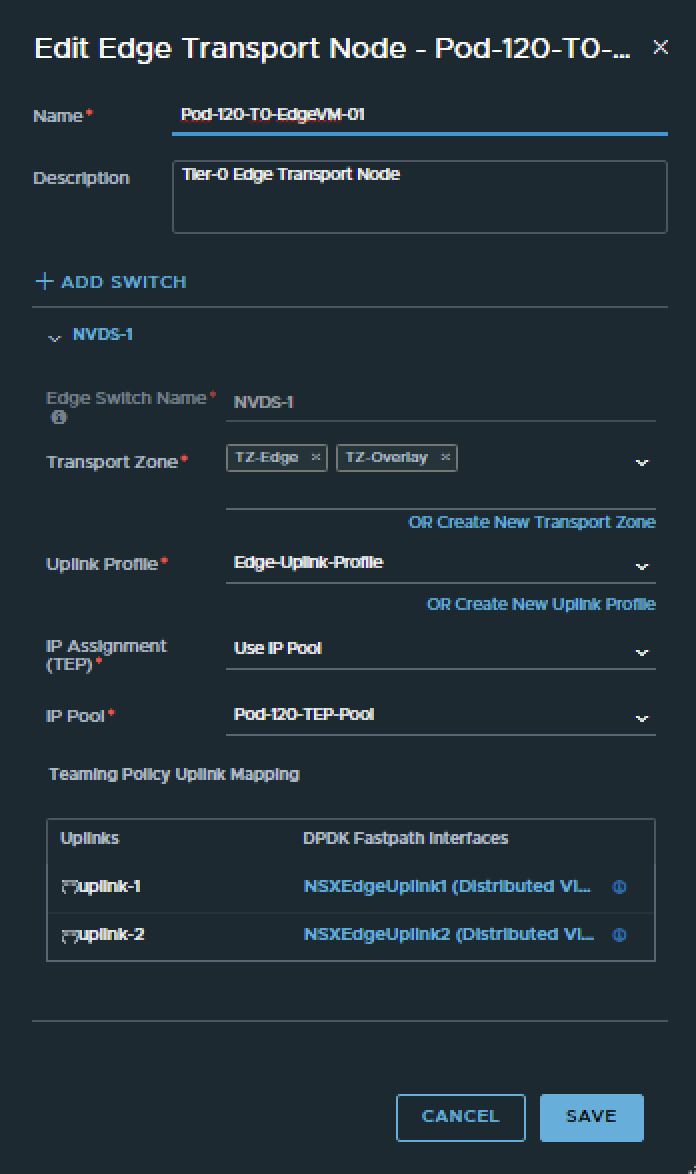
Pod-110 is using Virtual Edges. These Edges are responsible for hosting the Tier-0 Gateway. These Edges are using VDS Port Groups, NSX Uplink Profiles. Transport Zones with Uplink Teaming Policy Names just to make sure the Tier-0 Gateway is able to create its uplink interfaces for BGP peering over VLAN 116 and 117.
For reference I have included some of the Edge prerequisites below.
- VDS Port Groups
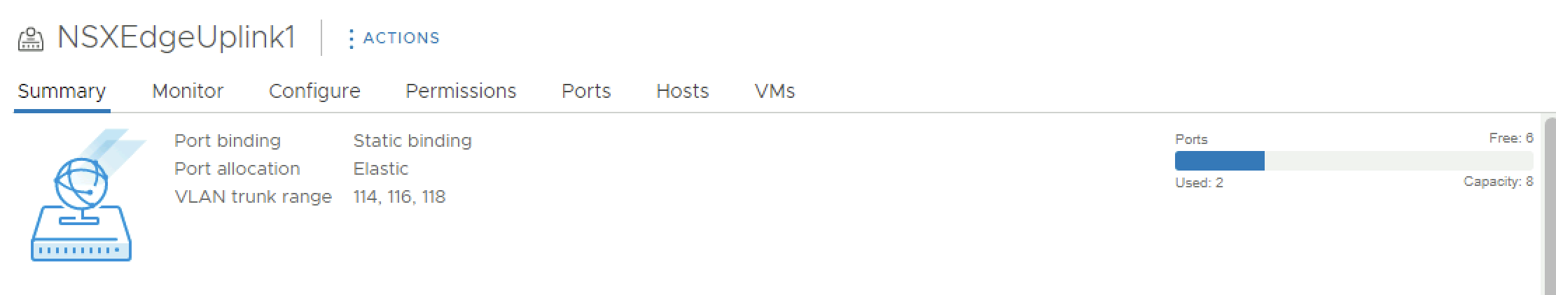
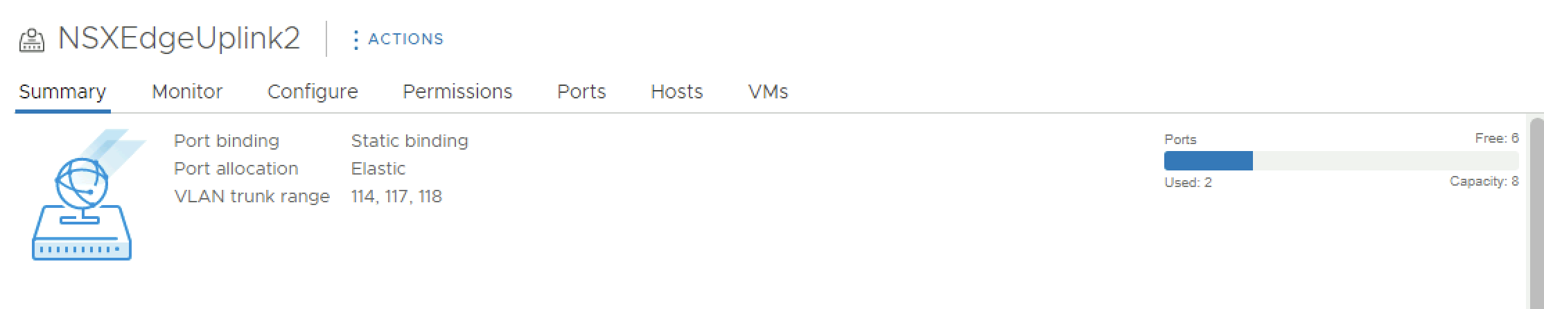
- NSX Edge Uplink Profiles
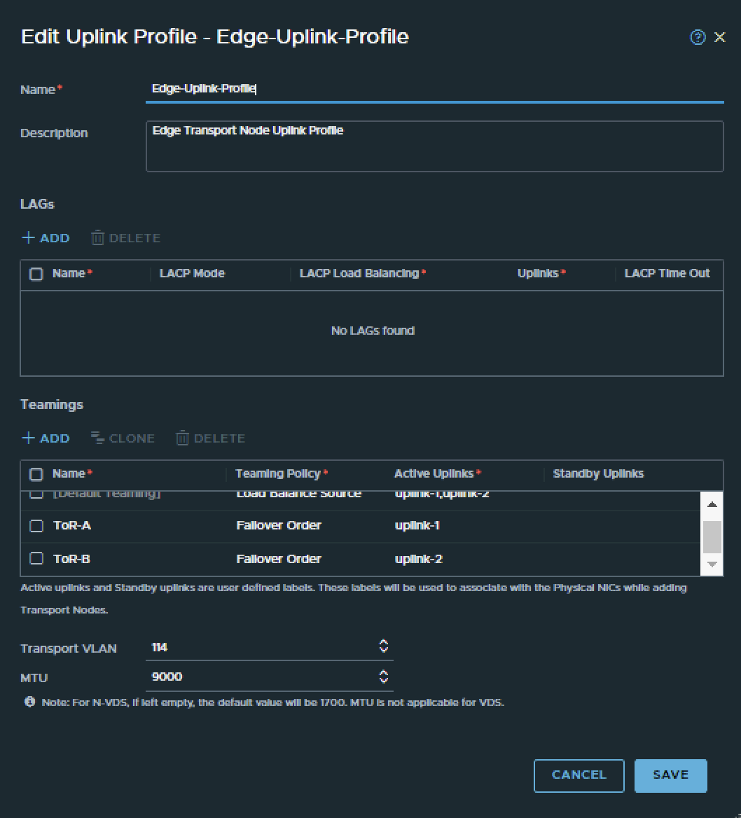
- NSX Edge Transport Zone

- NSX Edge configuration
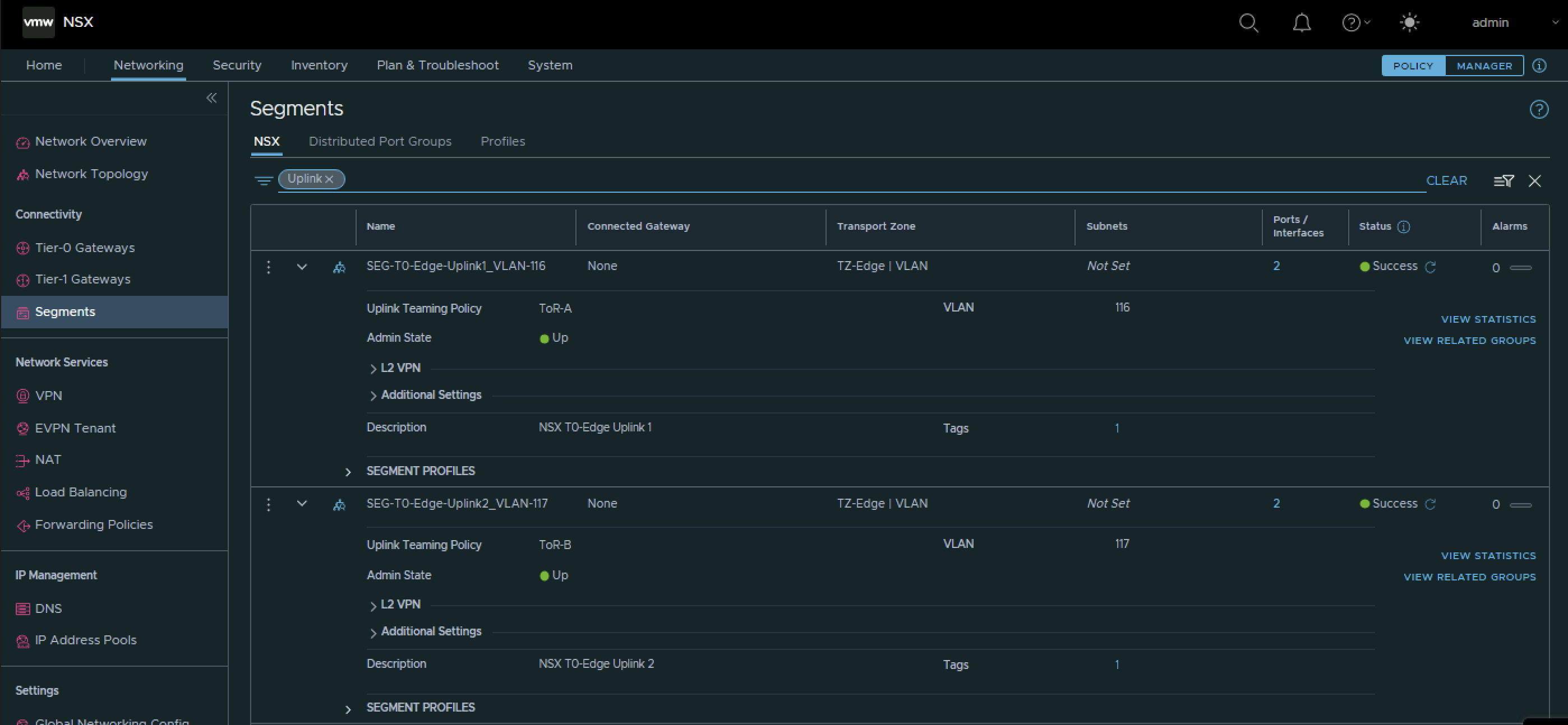
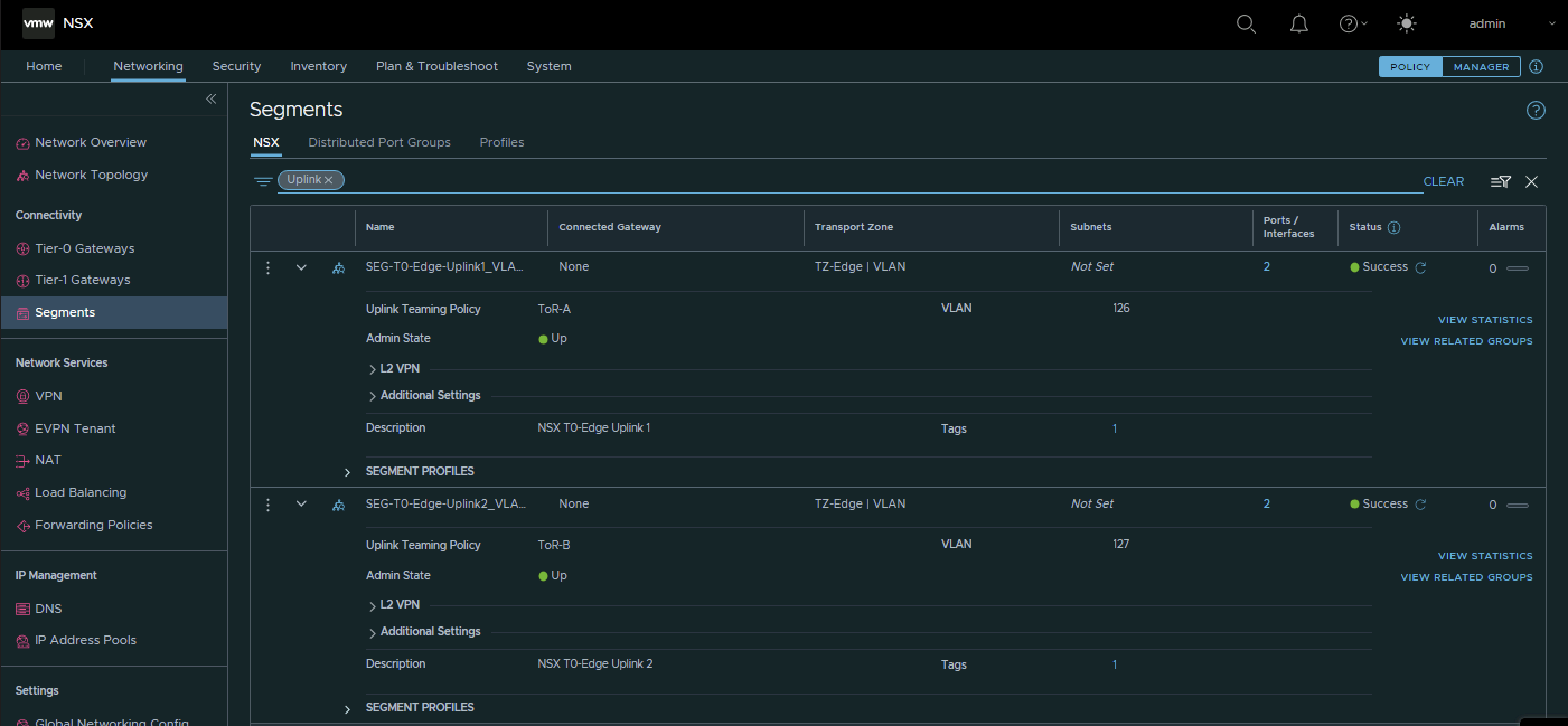
To configure the BGP peers towards the Pod-110 Router I have use the configuration parameters in the table below.
| Segment Name | Transport Zone | Uplink Teaming Policy | VLAN | IPv6 Network | IPv4 network |
|---|---|---|---|---|---|
| SEG-T0-Edge-Uplink1_VLAN-116 | VLAN | Tor-A | 116 | fd00:0:0:74::/64 | 10.203.116.0/24 |
| SEG-T0-Edge-Uplink2_VLAN-117 | VLAN | Tor-B | 117 | fd00:0:0:75::/64 | 10.203.117.0/24 |
This is the output of both segments after I have created them.
Pod 120
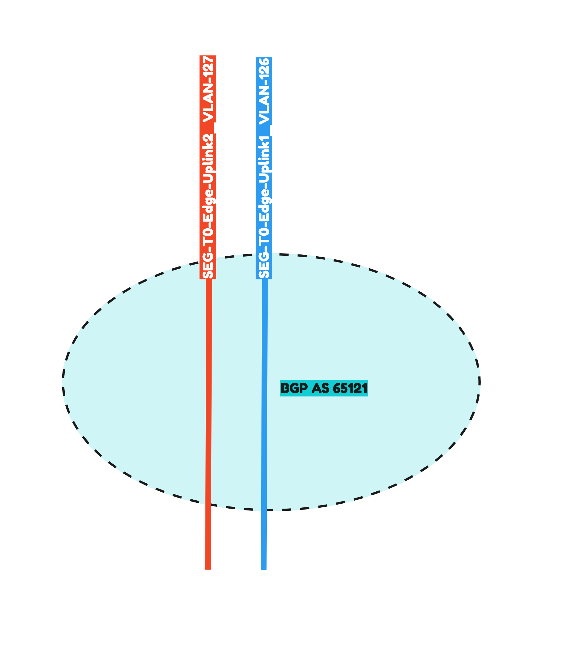
Pod-120 is using Virtual Edges. These Edges are responsible for hosting the Tier-0 Gateway. These Edges are using VDS Port Groups, NSX Uplink Profiles. Transport Zones with Uplink Teaming Policy Names just to make sure the Tier-0 Gateway is able to create its uplink interfaces for BGP peering over VLAN 126 and 127.
- VDS Port Groups
- NSX Edge Uplink Profiles
- NSX Edge Transport Zone
- NSX Edge configuration
To configure the BGP peers towards the Pod-120 Router I have use the configuration parameters in the table below.
| Segment Name | Transport Zone | Uplink Teaming Policy | VLAN | IPv6 Network | IPv4 network |
|---|---|---|---|---|---|
| SEG-T0-Edge-Uplink1_VLAN-126 | VLAN | Tor-A | 126 | fd00:0:0:7e::/64 | 10.203.126.0/24 |
| SEG-T0-Edge-Uplink2_VLAN-127 | VLAN | Tor-B | 127 | fd00:0:0:7f::/64 | 10.203.127.0/24 |
This is the output of both segments after I have created them.
STEP 5» Create a Tier–0 Gateway
Now it is time to create the Tier-0 Gateways and configure the Uplink Interfaces for the BGP and uplink network traffic.
Pod 110
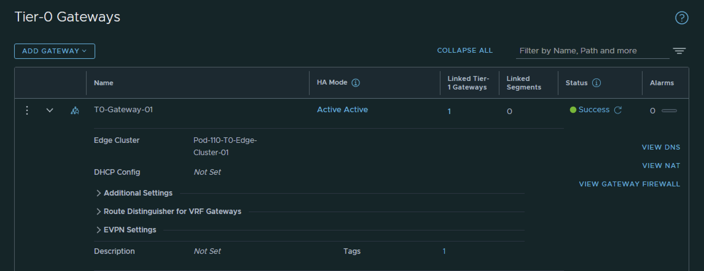
I have created the Tier-0 Gateway using the configuration parameters in the table below.
| Name | Edge Cluster |
|---|---|
| T0-Gateway-01 | T0-Pod-110-T0-Edge-Cluster-01 |
This is the output of the Tier-0 Gateway after I have created it.
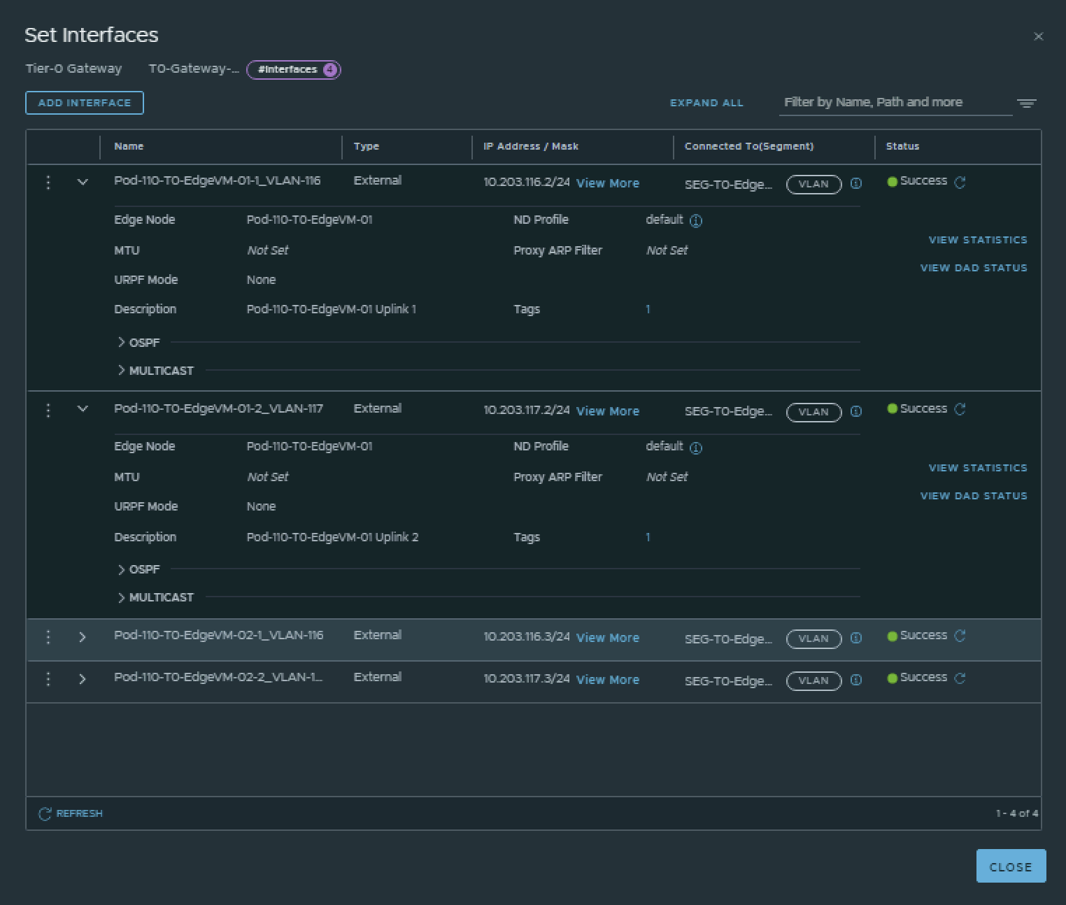
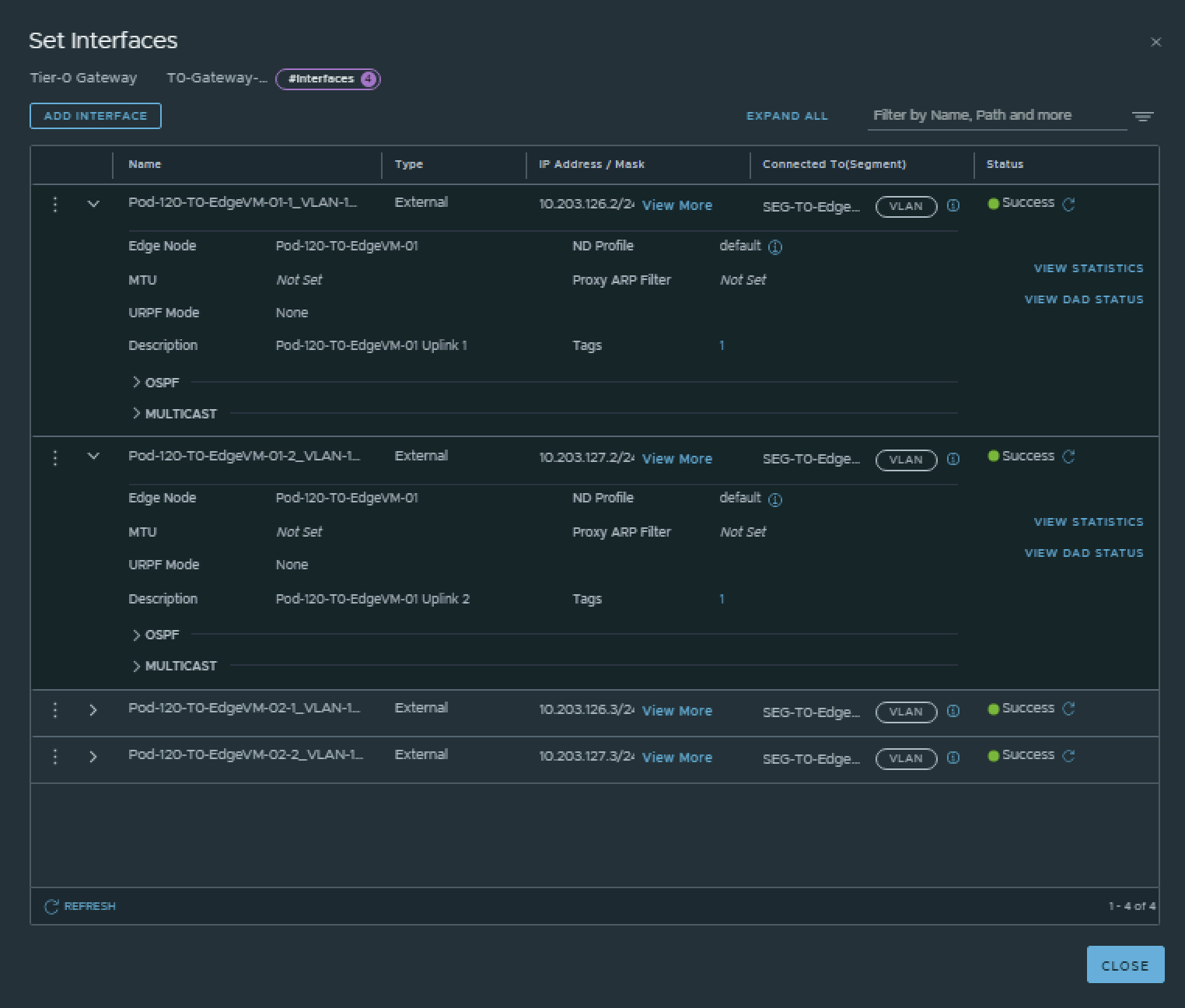
I have created the Tier-0 Gateway uplink interfaces using the configuration parameters in the table below.
| Interface Name | Edge Node | Segment | IPv4 Address | IPv6 Address |
|---|---|---|---|---|
| Pod-110-T0-EdgeVM-01-1_VLAN-116 | Pod-110-T0-EdgeVM-01 | SEG-T0-Edge-Uplink1_VLAN-116 | 10.203.116.2/24 | fd00:0000:0000:0074::0002/64 |
| Pod-110-T0-EdgeVM-01-2_VLAN-117 | Pod-110-T0-EdgeVM-01 | SEG-T0-Edge-Uplink2_VLAN-117 | 10.203.117.2/24 | fd00:0000:0000:0075::0002/64 |
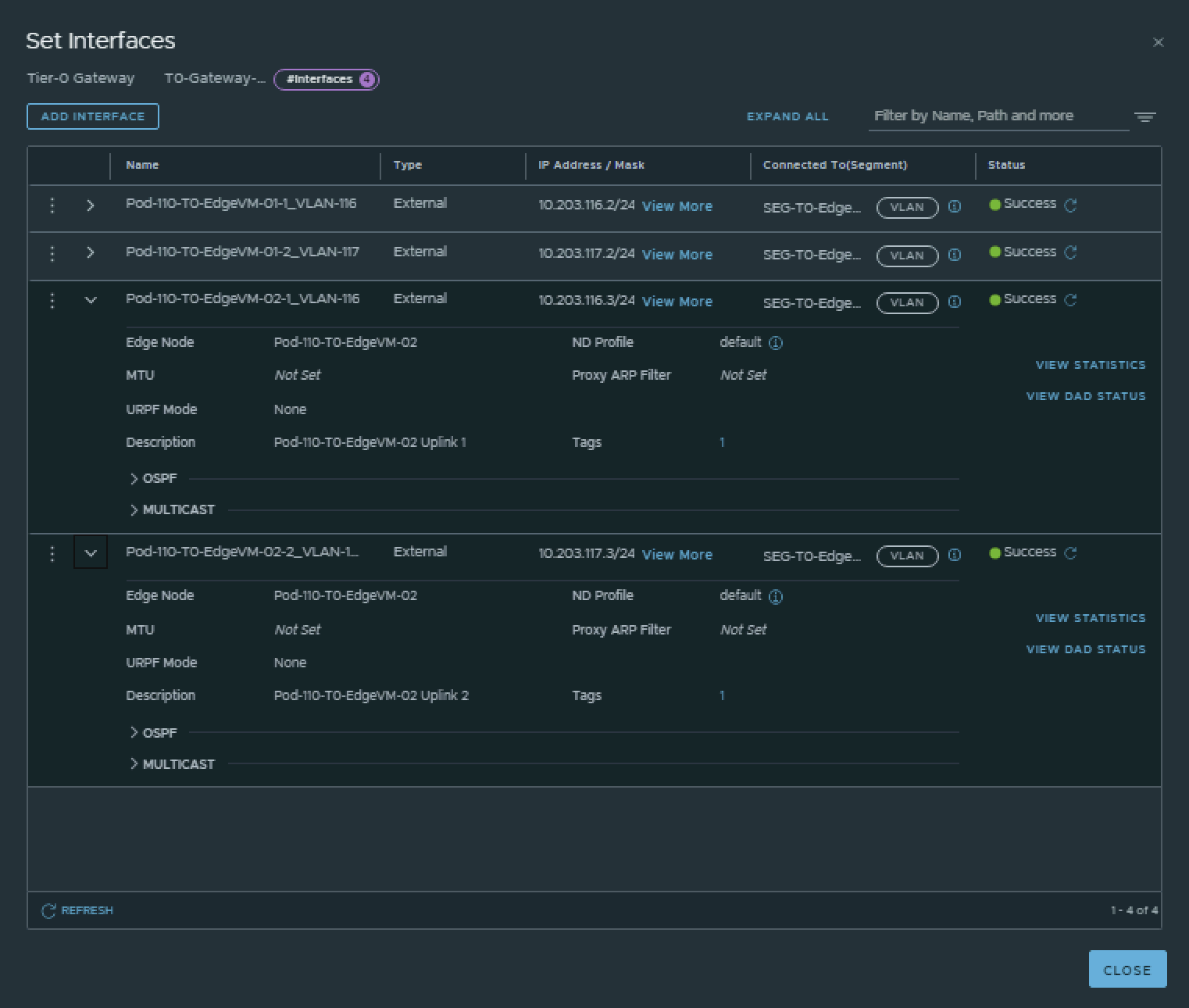
| Pod-110-T0-EdgeVM-02-1_VLAN-116 | Pod-110-T0-EdgeVM-02 | SEG-T0-Edge-Uplink1_VLAN-116 | 10.203.116.3/24 | fd00:0000:0000:0074::0003/64 |
| Pod-110-T0-EdgeVM-02-2_VLAN-117 | Pod-110-T0-EdgeVM-02 | SEG-T0-Edge-Uplink2_VLAN-117 | 10.203.117.3/24 | fd00:0000:0000:0075::0003/64 |
This is the output of the EdgeVM-01 interfaces after I have created them.
This is the output of the EdgeVM-02 interfaces after I have created them.
Pod 120
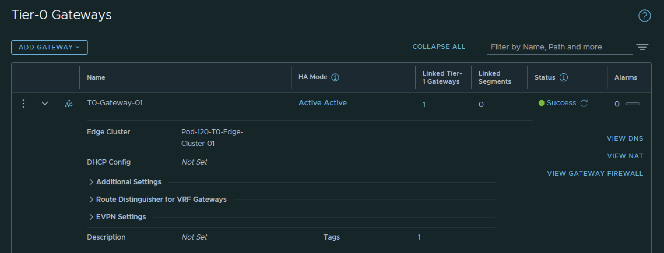
I have created the Tier-0 Gateway using the configuration parameters in the table below.
| Name | Edge Cluster |
|---|---|
| T0-Gateway-01 | T0-Pod-120-T0-Edge-Cluster-01 |
This is the output of the Tier-0 Gateway after I have created it.
I have created the Tier-0 Gateway uplink interfaces using the configuration parameters in the table below.
| Interface Name | Edge Node | Segment | IPv4 Address | IPv6 Address |
|---|---|---|---|---|
| Pod-120-T0-EdgeVM-01-1_VLAN-126 | Pod-120-T0-EdgeVM-01 | SEG-T0-Edge-Uplink1_VLAN-126 | 10.203.126.2/24 | fd00:0000:0000:007e::0002/64 |
| Pod-120-T0-EdgeVM-01-2_VLAN-127 | Pod-120-T0-EdgeVM-01 | SEG-T0-Edge-Uplink2_VLAN-127 | 10.203.127.2/24 | fd00:0000:0000:007f::0002/64 |
| Pod-120-T0-EdgeVM-02-1_VLAN-126 | Pod-120-T0-EdgeVM-02 | SEG-T0-Edge-Uplink1_VLAN-126 | 10.203.126.3/24 | fd00:0000:0000:007e::0003/64 |
| Pod-120-T0-EdgeVM-02-2_VLAN-127 | Pod-120-T0-EdgeVM-02 | SEG-T0-Edge-Uplink2_VLAN-127 | 10.203.127.3/24 | fd00:0000:0000:007f::0003/64 |
This is the output of the EdgeVM-01 interfaces after I have created them.
This is the output of the EdgeVM-02 interfaces after I have created them.

STEP 6» Configure IPv6 BGP Routing between Tier–0 Gateway and the Pod Gateway
Now that the Tier-0 Gateway is in place and the uplink interfaces are configured I am going to configure BGP on the Tier-0 Gateway. BGP is already configured on the POD-Router in one of the previous steps.
Pod 110
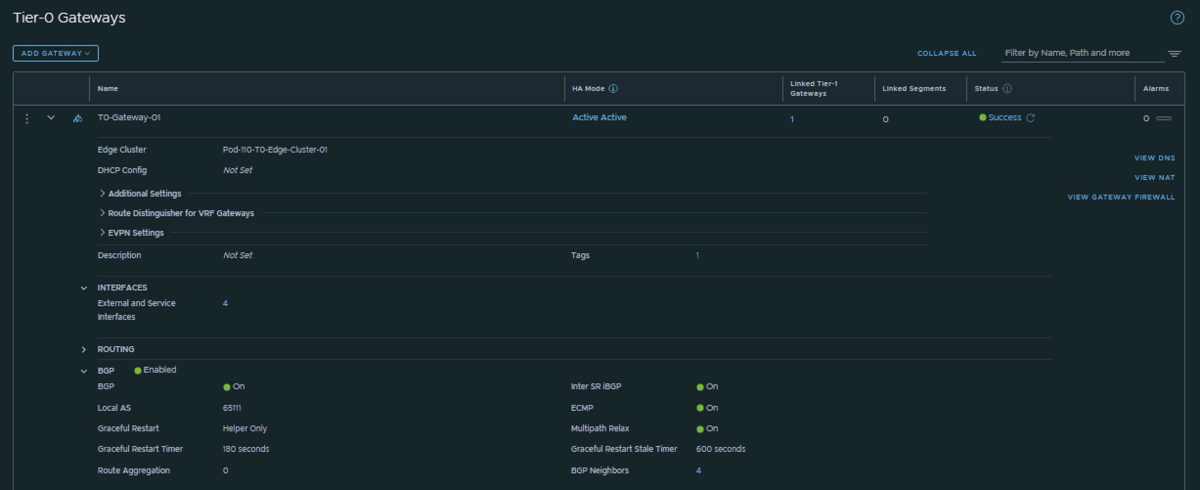
I have configured BGP using the configuration parameters in the table below.
| T0-Gateway-01 | |
|---|---|
| BGP | enabled |
| Local AS | 65111 |
| Inter SR iBGP | on |
| ECMP | on |
| Multipath Relax | on |
This is the output of the Tier-0 Gateway’s BGP configuration.
Now that BGP is enabled I will configure the actual neighbors towards the Pod-110 Router.
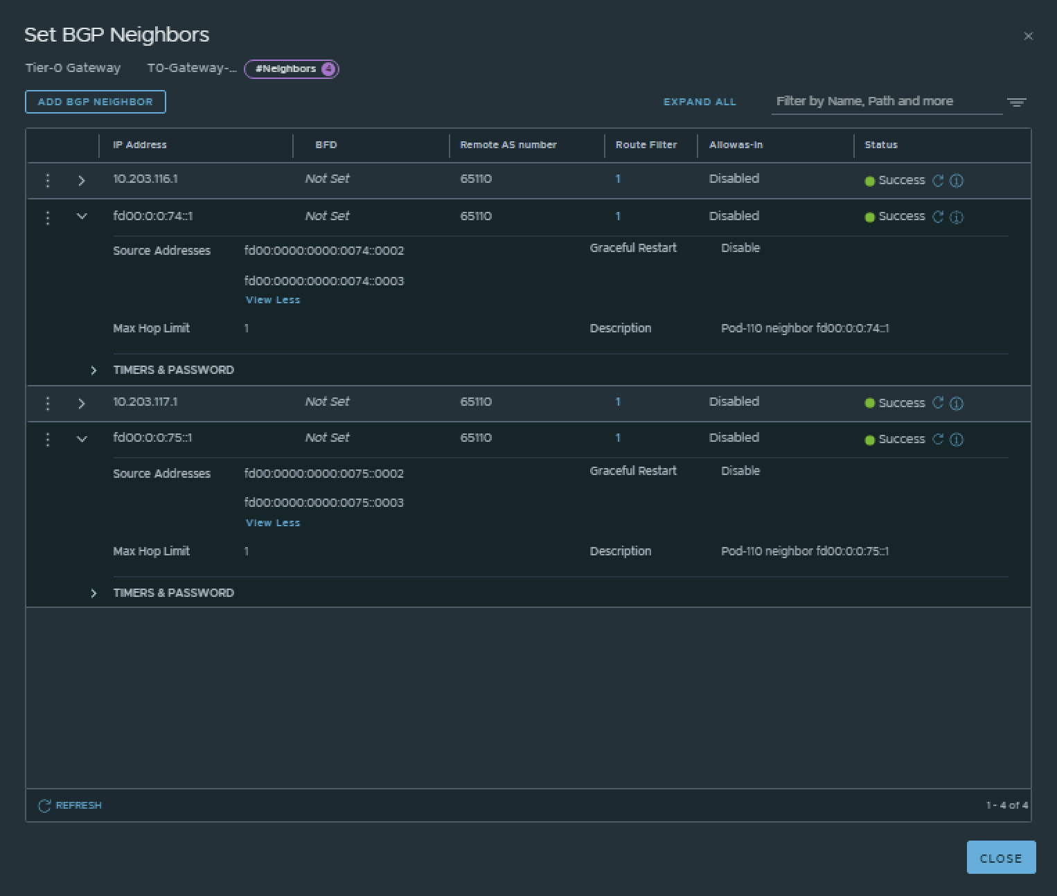
I have configured the BGP neighbors using the configuration parameters in the table below.
| Neigbor | Local AS | Remote AS | Peer IPv4 | Source IPv4 | Peer IPv6 | Source IPv6 |
|---|---|---|---|---|---|---|
| Pod-110-Router | 65111 | 65110 | 10.203.116.1 | 10.203.116.2 10.203.116.3 |
fd00:0:0:74::1 | fd00:0000:0000:0074::0002 fd00:0000:0000:0074::0003 |
| Pod-110-Router | 65111 | 65110 | 10.203.117.1 | 10.203.117.2 10.203.117.3 |
fd00:0:0:75::1 | fd00:0000:0000:0075::0002 fd00:0000:0000:0075::0003 |
This is the output of the Tier-0 Gateway’s BGP neighbor configuration for IPv4.

This is the output of the Tier-0 Gateway’s BGP neighbor configuration for IPv6.
💡
The BGP neighbors on the Tier-0 Gateways can be verified on both Edge-VMs by logging into the Tier-0 SR VRF (not the DR).
vyos@Pod-110-Router:~$ show ip bgp neighbors
BGP neighbor is 10.203.0.1, remote AS 65000, local AS 65110, external link
 Description: Lab-Router
  BGP version 4, remote router ID 0.0.0.0, local router ID 10.203.110.1
  BGP state = Active
  Last read 6d04h11m, Last write never
  Hold time is 180, keepalive interval is 60 seconds
  Graceful restart information:
    Local GR Mode: Helper*
    Remote GR Mode: NotApplicable
    R bit: False
    Timers:
      Configured Restart Time(sec): 120
      Received Restart Time(sec): 0
  Message statistics:
    Inq depth is 0
    Outq depth is 0
                         Sent       Rcvd
    Opens:                  0          0
    Notifications:          0          0
    Updates:                0          0
    Keepalives:             0          0
    Route Refresh:          0          0
    Capability:             0          0
    Total:                  0          0
  Minimum time between advertisement runs is 0 seconds

 For address family: IPv4 Unicast
  Not part of any update group
  Community attribute sent to this neighbor(all)
  0 accepted prefixes

  Connections established 0; dropped 0
  Last reset 6d04h11m,  Waiting for peer OPEN
BGP Connect Retry Timer in Seconds: 120
Next connect timer due in 28 seconds
Read thread: off  Write thread: off  FD used: -1

BGP neighbor is 10.203.116.2, remote AS 65111, local AS 65110, external link
 Description: Pod-110-T0-EdgeVM-01-1
Hostname: Pod-110-T0-EdgeVM-01
  BGP version 4, remote router ID 0.0.0.0, local router ID 10.203.110.1
  BGP state = Active
  Last read 3d10h34m, Last write 3d07h08m
  Hold time is 180, keepalive interval is 60 seconds
  Graceful restart information:
    Local GR Mode: Helper*
    Remote GR Mode: NotApplicable
    R bit: False
    Timers:
      Configured Restart Time(sec): 120
      Received Restart Time(sec): 0
  Message statistics:
    Inq depth is 0
    Outq depth is 0
                         Sent       Rcvd
    Opens:                 66          1
    Notifications:        132          0
    Updates:                6          6
    Keepalives:          3830       3827
    Route Refresh:          0          0
    Capability:             0          0
    Total:               4034       3834
  Minimum time between advertisement runs is 0 seconds

 For address family: IPv4 Unicast
  Not part of any update group
  Community attribute sent to this neighbor(all)
  Default information originate, default not sent
  0 accepted prefixes

  Connections established 1; dropped 1
  Last reset 3d10h31m,   Notification sent (Hold Timer Expired)
BGP Connect Retry Timer in Seconds: 120
Next connect timer due in 89 seconds
Read thread: off  Write thread: off  FD used: -1

BGP neighbor is 10.203.116.3, remote AS 65111, local AS 65110, external link
 Description: Pod-110-T0-EdgeVM-02-1
Hostname: Pod-110-T0-EdgeVM-02
  BGP version 4, remote router ID 0.0.0.0, local router ID 10.203.110.1
  BGP state = Active
  Last read 20:36:28, Last write 20:36:29
  Hold time is 180, keepalive interval is 60 seconds
  Graceful restart information:
    Local GR Mode: Helper*
    Remote GR Mode: NotApplicable
    R bit: False
    Timers:
      Configured Restart Time(sec): 120
      Received Restart Time(sec): 0
  Message statistics:
    Inq depth is 0
    Outq depth is 0
                         Sent       Rcvd
    Opens:                 77          9
    Notifications:        152          2
    Updates:               15         16
    Keepalives:          4444       4418
    Route Refresh:          0          0
    Capability:             0          0
    Total:               4688       4445
  Minimum time between advertisement runs is 0 seconds

 For address family: IPv4 Unicast
  Not part of any update group
  Community attribute sent to this neighbor(all)
  Default information originate, default not sent
  0 accepted prefixes

  Connections established 9; dropped 9
  Last reset 20:36:14,   Notification received (Cease/Peer Unconfigured)
BGP Connect Retry Timer in Seconds: 120
Next connect timer due in 32 seconds
Read thread: off  Write thread: off  FD used: -1

BGP neighbor is 10.203.117.2, remote AS 65111, local AS 65110, external link
 Description: Pod-110-T0-EdgeVM-01-2
Hostname: Pod-110-T0-EdgeVM-01
  BGP version 4, remote router ID 0.0.0.0, local router ID 10.203.110.1
  BGP state = Active
  Last read 3d10h34m, Last write 3d07h08m
  Hold time is 180, keepalive interval is 60 seconds
  Graceful restart information:
    Local GR Mode: Helper*
    Remote GR Mode: NotApplicable
    R bit: False
    Timers:
      Configured Restart Time(sec): 120
      Received Restart Time(sec): 0
  Message statistics:
    Inq depth is 0
    Outq depth is 0
                         Sent       Rcvd
    Opens:                 65          1
    Notifications:        130          0
    Updates:                6          6
    Keepalives:          3830       3827
    Route Refresh:          0          0
    Capability:             0          0
    Total:               4031       3834
  Minimum time between advertisement runs is 0 seconds

 For address family: IPv4 Unicast
  Not part of any update group
  Community attribute sent to this neighbor(all)
  Default information originate, default not sent
  0 accepted prefixes

  Connections established 1; dropped 1
  Last reset 3d10h31m,   Notification sent (Hold Timer Expired)
BGP Connect Retry Timer in Seconds: 120
Next connect timer due in 79 seconds
Read thread: off  Write thread: off  FD used: -1

BGP neighbor is 10.203.117.3, remote AS 65111, local AS 65110, external link
 Description: Pod-110-T0-EdgeVM-02-2
Hostname: Pod-110-T0-EdgeVM-02
  BGP version 4, remote router ID 0.0.0.0, local router ID 10.203.110.1
  BGP state = Active
  Last read 20:36:23, Last write 20:36:25
  Hold time is 180, keepalive interval is 60 seconds
  Graceful restart information:
    Local GR Mode: Helper*
    Remote GR Mode: NotApplicable
    R bit: False
    Timers:
      Configured Restart Time(sec): 120
      Received Restart Time(sec): 0
  Message statistics:
    Inq depth is 0
    Outq depth is 0
                         Sent       Rcvd
    Opens:                 80         10
    Notifications:        156          2
    Updates:               16         17
    Keepalives:          4442       4414
    Route Refresh:          0          0
    Capability:             0          0
    Total:               4694       4443
  Minimum time between advertisement runs is 0 seconds

 For address family: IPv4 Unicast
  Not part of any update group
  Community attribute sent to this neighbor(all)
  Default information originate, default not sent
  0 accepted prefixes

  Connections established 10; dropped 10
  Last reset 20:36:14,   Notification received (Cease/Peer Unconfigured)
BGP Connect Retry Timer in Seconds: 120
Next connect timer due in 80 seconds
Read thread: off  Write thread: off  FD used: -1

BGP neighbor is fd00::1, remote AS 65000, local AS 65110, external link
 Description: Lab-Router
  BGP version 4, remote router ID 0.0.0.0, local router ID 10.203.110.1
  BGP state = Active
  Last read 6d04h11m, Last write never
  Hold time is 180, keepalive interval is 60 seconds
  Graceful restart information:
    Local GR Mode: Helper*
    Remote GR Mode: NotApplicable
    R bit: False
    Timers:
      Configured Restart Time(sec): 120
      Received Restart Time(sec): 0
  Message statistics:
    Inq depth is 0
    Outq depth is 0
                         Sent       Rcvd
    Opens:                  0          0
    Notifications:          0          0
    Updates:                0          0
    Keepalives:             0          0
    Route Refresh:          0          0
    Capability:             0          0
    Total:                  0          0
  Minimum time between advertisement runs is 0 seconds

 For address family: IPv6 Unicast
  Not part of any update group
  Community attribute sent to this neighbor(all)
  0 accepted prefixes

  Connections established 0; dropped 0
  Last reset 6d04h11m,  Waiting for peer OPEN
BGP Connect Retry Timer in Seconds: 120
Next connect timer due in 29 seconds
Read thread: off  Write thread: off  FD used: -1

BGP neighbor is fd00:0:0:74::2, remote AS 65111, local AS 65110, external link
 Description: Pod-110-T0-EdgeVM-01-1
Hostname: Pod-110-T0-EdgeVM-01
  BGP version 4, remote router ID 0.0.0.0, local router ID 10.203.110.1
  BGP state = Active
  Last read 3d10h34m, Last write 3d07h08m
  Hold time is 180, keepalive interval is 60 seconds
  Graceful restart information:
    Local GR Mode: Helper*
    Remote GR Mode: NotApplicable
    R bit: False
    Timers:
      Configured Restart Time(sec): 120
      Received Restart Time(sec): 0
  Message statistics:
    Inq depth is 0
    Outq depth is 0
                         Sent       Rcvd
    Opens:                 65          1
    Notifications:        130          0
    Updates:                7          6
    Keepalives:          3830       3827
    Route Refresh:          0          0
    Capability:             0          0
    Total:               4032       3834
  Minimum time between advertisement runs is 0 seconds

 For address family: IPv6 Unicast
  Not part of any update group
  Community attribute sent to this neighbor(all)
  Default information originate, default not sent
  0 accepted prefixes

  Connections established 1; dropped 1
  Last reset 3d10h31m,   Notification sent (Hold Timer Expired)
BGP Connect Retry Timer in Seconds: 120
Next connect timer due in 85 seconds
Read thread: off  Write thread: off  FD used: -1

BGP neighbor is fd00:0:0:74::3, remote AS 65111, local AS 65110, external link
 Description: Pod-110-T0-EdgeVM-02-1
Hostname: Pod-110-T0-EdgeVM-02
  BGP version 4, remote router ID 0.0.0.0, local router ID 10.203.110.1
  BGP state = Active
  Last read 20:36:25, Last write 20:36:25
  Hold time is 180, keepalive interval is 60 seconds
  Graceful restart information:
    Local GR Mode: Helper*
    Remote GR Mode: NotApplicable
    R bit: False
    Timers:
      Configured Restart Time(sec): 120
      Received Restart Time(sec): 0
  Message statistics:
    Inq depth is 0
    Outq depth is 0
                         Sent       Rcvd
    Opens:                 78          9
    Notifications:        154          2
    Updates:               16         15
    Keepalives:          4444       4418
    Route Refresh:          0          0
    Capability:             0          0
    Total:               4692       4444
  Minimum time between advertisement runs is 0 seconds

 For address family: IPv6 Unicast
  Not part of any update group
  Community attribute sent to this neighbor(all)
  Default information originate, default not sent
  0 accepted prefixes

  Connections established 9; dropped 9
  Last reset 20:36:13,   Notification received (Cease/Peer Unconfigured)
BGP Connect Retry Timer in Seconds: 120
Next connect timer due in 64 seconds
Read thread: off  Write thread: off  FD used: -1

BGP neighbor is fd00:0:0:75::2, remote AS 65111, local AS 65110, external link
 Description: Pod-110-T0-EdgeVM-01-2
Hostname: Pod-110-T0-EdgeVM-01
  BGP version 4, remote router ID 0.0.0.0, local router ID 10.203.110.1
  BGP state = Active
  Last read 3d10h34m, Last write 3d07h08m
  Hold time is 180, keepalive interval is 60 seconds
  Graceful restart information:
    Local GR Mode: Helper*
    Remote GR Mode: NotApplicable
    R bit: False
    Timers:
      Configured Restart Time(sec): 120
      Received Restart Time(sec): 0
  Message statistics:
    Inq depth is 0
    Outq depth is 0
                         Sent       Rcvd
    Opens:                 66          1
    Notifications:        132          0
    Updates:                6          6
    Keepalives:          3830       3827
    Route Refresh:          0          0
    Capability:             0          0
    Total:               4034       3834
  Minimum time between advertisement runs is 0 seconds

 For address family: IPv6 Unicast
  Not part of any update group
  Community attribute sent to this neighbor(all)
  Default information originate, default not sent
  0 accepted prefixes

  Connections established 1; dropped 1
  Last reset 3d10h31m,   Notification sent (Hold Timer Expired)
BGP Connect Retry Timer in Seconds: 120
Next connect timer due in 46 seconds
Read thread: off  Write thread: off  FD used: -1

BGP neighbor is fd00:0:0:75::3, remote AS 65111, local AS 65110, external link
 Description: Pod-110-T0-EdgeVM-02-2
Hostname: Pod-110-T0-EdgeVM-02
  BGP version 4, remote router ID 0.0.0.0, local router ID 10.203.110.1
  BGP state = Active
  Last read 20:36:23, Last write 20:36:23
  Hold time is 180, keepalive interval is 60 seconds
  Graceful restart information:
    Local GR Mode: Helper*
    Remote GR Mode: NotApplicable
    R bit: False
    Timers:
      Configured Restart Time(sec): 120
      Received Restart Time(sec): 0
  Message statistics:
    Inq depth is 0
    Outq depth is 0
                         Sent       Rcvd
    Opens:                 79         11
    Notifications:        156          2
    Updates:               19         16
    Keepalives:          4444       4414
    Route Refresh:          0          0
    Capability:             0          0
    Total:               4698       4443
  Minimum time between advertisement runs is 0 seconds

 For address family: IPv6 Unicast
  Not part of any update group
  Community attribute sent to this neighbor(all)
  Default information originate, default not sent
  0 accepted prefixes

  Connections established 11; dropped 11
  Last reset 20:36:13,   Notification received (Cease/Peer Unconfigured)
BGP Connect Retry Timer in Seconds: 120
Next connect timer due in 39 seconds
Read thread: off  Write thread: off  FD used: -1

vyos@Pod-110-Router:~$Pod-110-T0-EdgeVM-01> get logical-router
Wed Sep 07 2022 UTC 10:39:35.805
Logical Router
UUID VRF LR-ID Name Type Ports Neighbors736a80e3-23f6-5a2d-81d6-bbefb2786666 0 0 TUNNEL 4 16/5000
322f1657-3057-44cc-8b32-a947837afbf6 1 2 SR-T0-Gateway-01 SERVICE_ROUTER_TIER0 7 6/20000
85cbb437-7eab-41ca-99d8-f06655c1c339 3 1 DR-T0-Gateway-01 DISTRIBUTED_ROUTER_TIER0 5 2/20000
23184393-a35e-46df-989c-6af86651f127 4 3 DR-T1-Gateway-01 DISTRIBUTED_ROUTER_TIER1 7 2/20000
Pod-110-T0-EdgeVM-01> vrf 1
Pod-110-T0-EdgeVM-01(tier0_sr[1])> get bgp neighbor summary
BFD States: NC - Not configured, DC - Disconnected
AD - Admin down, DW - Down, IN - Init, UP - Up
BGP summary information for VRF default for address-family: ipv4Unicast
Router ID: 10.203.116.2 Local AS: 65111
Neighbor AS State Up/DownTime BFD InMsgs OutMsgs InPfx OutPfx
10.203.116.1 65110 Estab 03:42:03 NC 228 228 1 5
10.203.117.1 65110 Estab 03:42:03 NC 228 228 1 6
BFD States: NC - Not configured, DC - Disconnected
AD - Admin down, DW - Down, IN - Init, UP - Up
BGP summary information for VRF default for address-family: ipv6Unicast
Router ID: 10.203.116.2 Local AS: 65111
Neighbor AS State Up/DownTime BFD InMsgs OutMsgs InPfx OutPfx
fd00:0:0:74::1 65110 Estab 03:42:03 NC 228 228 1 5
fd00:0:0:75::1 65110 Estab 03:42:03 NC 228 228 1 6
Wed Sep 07 2022 UTC 10:40:00.202
Pod-110-T0-EdgeVM-01(tier0_sr[1])>Pod-110-T0-EdgeVM-02> get logical-router
Wed Sep 07 2022 UTC 10:40:33.273
Logical Router
UUID VRF LR-ID Name Type Ports Neighbors736a80e3-23f6-5a2d-81d6-bbefb2786666 0 0 TUNNEL 4 16/5000
85cbb437-7eab-41ca-99d8-f06655c1c339 1 1 DR-T0-Gateway-01 DISTRIBUTED_ROUTER_TIER0 5 2/20000
120dbcf7-2d18-4bb6-94a3-b4797adb5b1b 2 8 SR-T0-Gateway-01 SERVICE_ROUTER_TIER0 7 6/20000
23184393-a35e-46df-989c-6af86651f127 4 3 DR-T1-Gateway-01 DISTRIBUTED_ROUTER_TIER1 7 2/20000
Pod-110-T0-EdgeVM-02> vrf 2
Pod-110-T0-EdgeVM-02(tier0_sr[2])> get bgp neighbor summary
BFD States: NC - Not configured, DC - Disconnected
AD - Admin down, DW - Down, IN - Init, UP - Up
BGP summary information for VRF default for address-family: ipv4Unicast
Router ID: 10.203.117.3 Local AS: 65111
Neighbor AS State Up/DownTime BFD InMsgs OutMsgs InPfx OutPfx
10.203.116.1 65110 Estab 03:42:46 NC 228 228 1 5
10.203.117.1 65110 Estab 03:42:46 NC 228 228 1 6
BFD States: NC - Not configured, DC - Disconnected
AD - Admin down, DW - Down, IN - Init, UP - Up
BGP summary information for VRF default for address-family: ipv6Unicast
Router ID: 10.203.117.3 Local AS: 65111
Neighbor AS State Up/DownTime BFD InMsgs OutMsgs InPfx OutPfx
fd00:0:0:74::1 65110 Estab 03:42:46 NC 228 228 1 5
fd00:0:0:75::1 65110 Estab 03:42:46 NC 228 228 1 6
Wed Sep 07 2022 UTC 10:40:49.136
Pod-110-T0-EdgeVM-02(tier0_sr[2])>
Pod 120
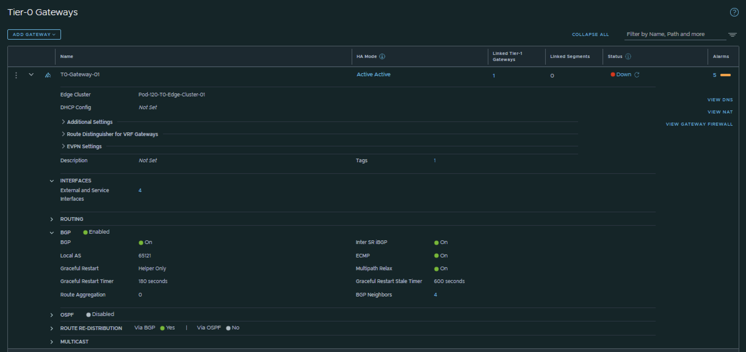
I have configured BGP using the configuration parameters in the table below.
| T0-Gateway-01 | |
|---|---|
| BGP | enabled |
| Local AS | 65121 |
| Inter SR iBGP | on |
| ECMP | on |
| Multipath Relax | on |
This is the output of the Tier-0 Gateway’s BGP configuration.
Now that BGP is enabled I will configure the actual neighbors towards the Pod-120 Router.
I have configured the BGP neighbors using the configuration parameters in the table below.
| Neigbor | Local AS | Remote AS | Peer IPv4 | Source IPv4 | Peer IPv6 | Source IPv6 |
|---|---|---|---|---|---|---|
| Pod-120-Router | 65121 | 65120 | 10.203.126.1 | 10.203.126.2 10.203.126.3 |
fd00:0:0:7e::1 | fd00:0000:0000:007e::0002 fd00:0000:0000:007e::0003 |
| Pod-120-Router | 65121 | 65120 | 10.203.127.1 | 10.203.127.2 10.203.127.3 |
fd00:0:0:7f::1 | fd00:0000:0000:007f::0002 fd00:0000:0000:007f::0003 |
This is the output of the Tier-0 Gateway’s BGP neighbor configuration for IPv4.
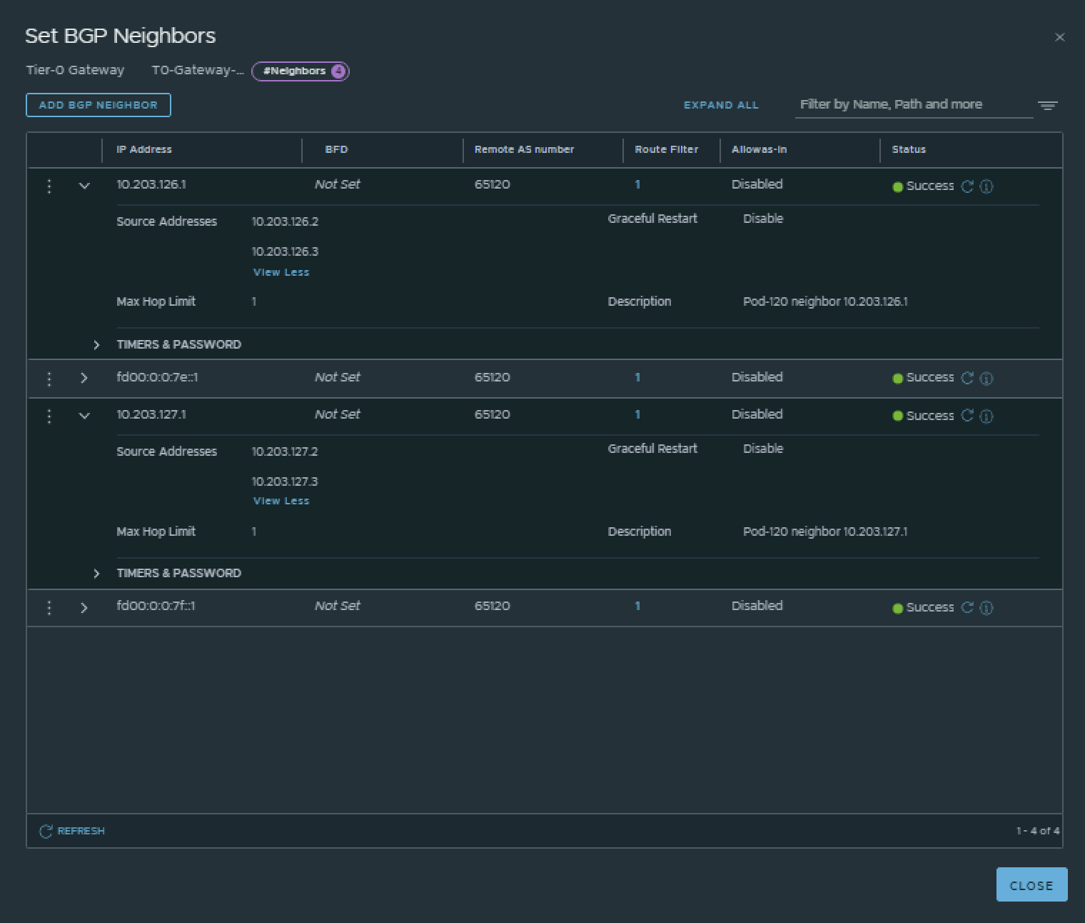
This is the output of the Tier-0 Gateway’s BGP neighbor configuration for IPv6.
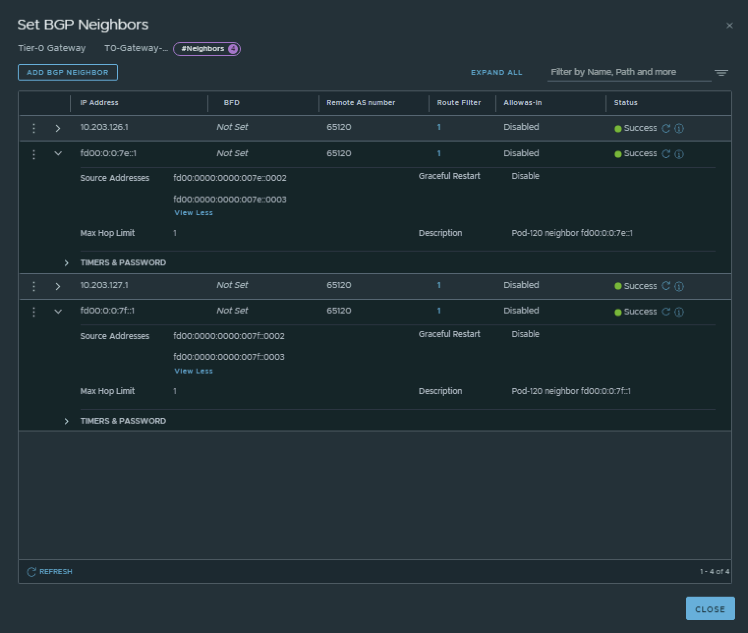
💡
The BGP neighbors on the Tier-0 Gateways can be verified on both Edge-VMs by logging into the Tier-0 SR VRF (not the DR).
vyos@Pod-120-Router:~$ show ip bgp neighbors
BGP neighbor is 10.203.0.1, remote AS 65000, local AS 65120, external link
 Description: Lab-Router
  BGP version 4, remote router ID 0.0.0.0, local router ID 10.203.120.1
  BGP state = Active
  Last read 5d18h40m, Last write never
  Hold time is 180, keepalive interval is 60 seconds
  Graceful restart information:
    Local GR Mode: Helper*
    Remote GR Mode: NotApplicable
    R bit: False
    Timers:
      Configured Restart Time(sec): 120
      Received Restart Time(sec): 0
  Message statistics:
    Inq depth is 0
    Outq depth is 0
                         Sent       Rcvd
    Opens:                  0          0
    Notifications:          0          0
    Updates:                0          0
    Keepalives:             0          0
    Route Refresh:          0          0
    Capability:             0          0
    Total:                  0          0
  Minimum time between advertisement runs is 0 seconds

 For address family: IPv4 Unicast
  Not part of any update group
  Community attribute sent to this neighbor(all)
  0 accepted prefixes

  Connections established 0; dropped 0
  Last reset 5d18h40m,  Waiting for peer OPEN
BGP Connect Retry Timer in Seconds: 120
Next connect timer due in 95 seconds
Read thread: off  Write thread: off  FD used: -1

BGP neighbor is 10.203.126.2, remote AS 65121, local AS 65120, external link
 Description: Pod-120-T0-EdgeVM-01-1
Hostname: Pod-120-T0-EdgeVM-01
  BGP version 4, remote router ID 10.203.126.2, local router ID 10.203.120.1
  BGP state = Established, up for 5d16h35m
  Last read 00:00:39, Last write 00:00:40
  Hold time is 180, keepalive interval is 60 seconds
  Neighbor capabilities:
    4 Byte AS: advertised and received
    Extended Message: advertised
    AddPath:
      IPv4 Unicast: RX advertised and received
    Route refresh: advertised and received(old & new)
    Enhanced Route Refresh: advertised
    Address Family IPv4 Unicast: advertised and received
    Hostname Capability: advertised (name: Pod-120-Router,domain name: n/a) received (name: Pod-120-T0-EdgeVM-01,domain name: n/a)
    Graceful Restart Capability: advertised
  Graceful restart information:
    Local GR Mode: Helper*
    Remote GR Mode: Disable
    R bit: False
    Timers:
      Configured Restart Time(sec): 120
      Received Restart Time(sec): 0
  Message statistics:
    Inq depth is 0
    Outq depth is 0
                         Sent       Rcvd
    Opens:                  1          1
    Notifications:          0          0
    Updates:                3          4
    Keepalives:          8196       8196
    Route Refresh:          0          0
    Capability:             0          0
    Total:               8200       8201
  Minimum time between advertisement runs is 0 seconds

 For address family: IPv4 Unicast
  Update group 3, subgroup 3
  Packet Queue length 0
  Community attribute sent to this neighbor(all)
  Default information originate, default sent
  5 accepted prefixes

  Connections established 1; dropped 0
  Last reset 5d18h40m,  No AFI/SAFI activated for peer
Local host: 10.203.126.1, Local port: 179
Foreign host: 10.203.126.2, Foreign port: 39979
Nexthop: 10.203.126.1
Nexthop global: fd00:0:0:7e::1
Nexthop local: fe80::20c:29ff:fee3:7980
BGP connection: shared network
BGP Connect Retry Timer in Seconds: 120
Estimated round trip time: 5 ms
Read thread: on  Write thread: on  FD used: 34

BGP neighbor is 10.203.126.3, remote AS 65121, local AS 65120, external link
 Description: Pod-120-T0-EdgeVM-02-1
Hostname: Pod-120-T0-EdgeVM-02
  BGP version 4, remote router ID 10.203.127.3, local router ID 10.203.120.1
  BGP state = Established, up for 5d16h35m
  Last read 00:00:53, Last write 00:00:54
  Hold time is 180, keepalive interval is 60 seconds
  Neighbor capabilities:
    4 Byte AS: advertised and received
    Extended Message: advertised
    AddPath:
      IPv4 Unicast: RX advertised and received
    Route refresh: advertised and received(old & new)
    Enhanced Route Refresh: advertised
    Address Family IPv4 Unicast: advertised and received
    Hostname Capability: advertised (name: Pod-120-Router,domain name: n/a) received (name: Pod-120-T0-EdgeVM-02,domain name: n/a)
    Graceful Restart Capability: advertised
  Graceful restart information:
    Local GR Mode: Helper*
    Remote GR Mode: Disable
    R bit: False
    Timers:
      Configured Restart Time(sec): 120
      Received Restart Time(sec): 0
  Message statistics:
    Inq depth is 0
    Outq depth is 0
                         Sent       Rcvd
    Opens:                 61          2
    Notifications:          0          2
    Updates:                3          4
    Keepalives:          8197       8197
    Route Refresh:          0          0
    Capability:             0          0
    Total:               8261       8205
  Minimum time between advertisement runs is 0 seconds

 For address family: IPv4 Unicast
  Update group 3, subgroup 3
  Packet Queue length 0
  Community attribute sent to this neighbor(all)
  Default information originate, default sent
  5 accepted prefixes

  Connections established 2; dropped 1
  Last reset 5d18h35m,  No AFI/SAFI activated for peer
Local host: 10.203.126.1, Local port: 179
Foreign host: 10.203.126.3, Foreign port: 46401
Nexthop: 10.203.126.1
Nexthop global: fd00:0:0:7e::1
Nexthop local: fe80::20c:29ff:fee3:7980
BGP connection: shared network
BGP Connect Retry Timer in Seconds: 120
Estimated round trip time: 4 ms
Read thread: on  Write thread: on  FD used: 28

BGP neighbor is 10.203.127.2, remote AS 65121, local AS 65120, external link
 Description: Pod-120-T0-EdgeVM-01-2
Hostname: Pod-120-T0-EdgeVM-01
  BGP version 4, remote router ID 10.203.126.2, local router ID 10.203.120.1
  BGP state = Established, up for 5d16h35m
  Last read 00:00:39, Last write 00:00:40
  Hold time is 180, keepalive interval is 60 seconds
  Neighbor capabilities:
    4 Byte AS: advertised and received
    Extended Message: advertised
    AddPath:
      IPv4 Unicast: RX advertised and received
    Route refresh: advertised and received(old & new)
    Enhanced Route Refresh: advertised
    Address Family IPv4 Unicast: advertised and received
    Hostname Capability: advertised (name: Pod-120-Router,domain name: n/a) received (name: Pod-120-T0-EdgeVM-01,domain name: n/a)
    Graceful Restart Capability: advertised
  Graceful restart information:
    Local GR Mode: Helper*
    Remote GR Mode: Disable
    R bit: False
    Timers:
      Configured Restart Time(sec): 120
      Received Restart Time(sec): 0
  Message statistics:
    Inq depth is 0
    Outq depth is 0
                         Sent       Rcvd
    Opens:                  1          1
    Notifications:          0          0
    Updates:                3          4
    Keepalives:          8196       8196
    Route Refresh:          0          0
    Capability:             0          0
    Total:               8200       8201
  Minimum time between advertisement runs is 0 seconds

 For address family: IPv4 Unicast
  Update group 3, subgroup 3
  Packet Queue length 0
  Community attribute sent to this neighbor(all)
  Default information originate, default sent
  5 accepted prefixes

  Connections established 1; dropped 0
  Last reset 5d18h40m,  No AFI/SAFI activated for peer
Local host: 10.203.127.1, Local port: 179
Foreign host: 10.203.127.2, Foreign port: 39009
Nexthop: 10.203.127.1
Nexthop global: fd00:0:0:7f::1
Nexthop local: fe80::20c:29ff:fee3:7980
BGP connection: shared network
BGP Connect Retry Timer in Seconds: 120
Estimated round trip time: 5 ms
Read thread: on  Write thread: on  FD used: 35

BGP neighbor is 10.203.127.3, remote AS 65121, local AS 65120, external link
 Description: Pod-120-T0-EdgeVM-02-2
Hostname: Pod-120-T0-EdgeVM-02
  BGP version 4, remote router ID 10.203.127.3, local router ID 10.203.120.1
  BGP state = Established, up for 5d16h35m
  Last read 00:00:53, Last write 00:00:54
  Hold time is 180, keepalive interval is 60 seconds
  Neighbor capabilities:
    4 Byte AS: advertised and received
    Extended Message: advertised
    AddPath:
      IPv4 Unicast: RX advertised and received
    Route refresh: advertised and received(old & new)
    Enhanced Route Refresh: advertised
    Address Family IPv4 Unicast: advertised and received
    Hostname Capability: advertised (name: Pod-120-Router,domain name: n/a) received (name: Pod-120-T0-EdgeVM-02,domain name: n/a)
    Graceful Restart Capability: advertised
  Graceful restart information:
    Local GR Mode: Helper*
    Remote GR Mode: Disable
    R bit: False
    Timers:
      Configured Restart Time(sec): 120
      Received Restart Time(sec): 0
  Message statistics:
    Inq depth is 0
    Outq depth is 0
                         Sent       Rcvd
    Opens:                 61          2
    Notifications:          0          2
    Updates:                3          4
    Keepalives:          8197       8197
    Route Refresh:          0          0
    Capability:             0          0
    Total:               8261       8205
  Minimum time between advertisement runs is 0 seconds

 For address family: IPv4 Unicast
  Update group 3, subgroup 3
  Packet Queue length 0
  Community attribute sent to this neighbor(all)
  Default information originate, default sent
  5 accepted prefixes

  Connections established 2; dropped 1
  Last reset 5d18h35m,  No AFI/SAFI activated for peer
Local host: 10.203.127.1, Local port: 179
Foreign host: 10.203.127.3, Foreign port: 33637
Nexthop: 10.203.127.1
Nexthop global: fd00:0:0:7f::1
Nexthop local: fe80::20c:29ff:fee3:7980
BGP connection: shared network
BGP Connect Retry Timer in Seconds: 120
Estimated round trip time: 4 ms
Read thread: on  Write thread: on  FD used: 31

BGP neighbor is fd00::1, remote AS 65000, local AS 65120, external link
 Description: Lab-Router
  BGP version 4, remote router ID 0.0.0.0, local router ID 10.203.120.1
  BGP state = Active
  Last read 5d18h40m, Last write never
  Hold time is 180, keepalive interval is 60 seconds
  Graceful restart information:
    Local GR Mode: Helper*
    Remote GR Mode: NotApplicable
    R bit: False
    Timers:
      Configured Restart Time(sec): 120
      Received Restart Time(sec): 0
  Message statistics:
    Inq depth is 0
    Outq depth is 0
                         Sent       Rcvd
    Opens:                  0          0
    Notifications:          0          0
    Updates:                0          0
    Keepalives:             0          0
    Route Refresh:          0          0
    Capability:             0          0
    Total:                  0          0
  Minimum time between advertisement runs is 0 seconds

 For address family: IPv6 Unicast
  Not part of any update group
  Community attribute sent to this neighbor(all)
  0 accepted prefixes

  Connections established 0; dropped 0
  Last reset 5d18h40m,  Waiting for peer OPEN
BGP Connect Retry Timer in Seconds: 120
Next connect timer due in 111 seconds
Read thread: off  Write thread: off  FD used: -1

BGP neighbor is fd00:0:0:7e::2, remote AS 65121, local AS 65120, external link
 Description: Pod-120-T0-EdgeVM-01-1
Hostname: Pod-120-T0-EdgeVM-01
  BGP version 4, remote router ID 10.203.126.2, local router ID 10.203.120.1
  BGP state = Established, up for 5d16h35m
  Last read 00:00:39, Last write 00:00:40
  Hold time is 180, keepalive interval is 60 seconds
  Neighbor capabilities:
    4 Byte AS: advertised and received
    Extended Message: advertised
    AddPath:
      IPv6 Unicast: RX advertised and received
    Route refresh: advertised and received(old & new)
    Enhanced Route Refresh: advertised
    Address Family IPv6 Unicast: advertised and received
    Hostname Capability: advertised (name: Pod-120-Router,domain name: n/a) received (name: Pod-120-T0-EdgeVM-01,domain name: n/a)
    Graceful Restart Capability: advertised
  Graceful restart information:
    Local GR Mode: Helper*
    Remote GR Mode: Disable
    R bit: False
    Timers:
      Configured Restart Time(sec): 120
      Received Restart Time(sec): 0
  Message statistics:
    Inq depth is 0
    Outq depth is 0
                         Sent       Rcvd
    Opens:                  1          1
    Notifications:          0          0
    Updates:                3          4
    Keepalives:          8196       8196
    Route Refresh:          0          0
    Capability:             0          0
    Total:               8200       8201
  Minimum time between advertisement runs is 0 seconds

 For address family: IPv6 Unicast
  Update group 4, subgroup 4
  Packet Queue length 0
  Community attribute sent to this neighbor(all)
  Default information originate, default sent
  5 accepted prefixes

  Connections established 1; dropped 0
  Last reset 5d18h40m,  No AFI/SAFI activated for peer
Local host: fd00:0:0:7e::1, Local port: 179
Foreign host: fd00:0:0:7e::2, Foreign port: 33751
Nexthop: 10.203.126.1
Nexthop global: fd00:0:0:7e::1
Nexthop local: fe80::20c:29ff:fee3:7980
BGP connection: shared network
BGP Connect Retry Timer in Seconds: 120
Estimated round trip time: 4 ms
Read thread: on  Write thread: on  FD used: 36

BGP neighbor is fd00:0:0:7e::3, remote AS 65121, local AS 65120, external link
 Description: Pod-120-T0-EdgeVM-02-1
Hostname: Pod-120-T0-EdgeVM-02
  BGP version 4, remote router ID 10.203.127.3, local router ID 10.203.120.1
  BGP state = Established, up for 5d16h35m
  Last read 00:00:53, Last write 00:00:53
  Hold time is 180, keepalive interval is 60 seconds
  Neighbor capabilities:
    4 Byte AS: advertised and received
    Extended Message: advertised
    AddPath:
      IPv6 Unicast: RX advertised and received
    Route refresh: advertised and received(old & new)
    Enhanced Route Refresh: advertised
    Address Family IPv6 Unicast: advertised and received
    Hostname Capability: advertised (name: Pod-120-Router,domain name: n/a) received (name: Pod-120-T0-EdgeVM-02,domain name: n/a)
    Graceful Restart Capability: advertised
  Graceful restart information:
    Local GR Mode: Helper*
    Remote GR Mode: Disable
    R bit: False
    Timers:
      Configured Restart Time(sec): 120
      Received Restart Time(sec): 0
  Message statistics:
    Inq depth is 0
    Outq depth is 0
                         Sent       Rcvd
    Opens:                 61          2
    Notifications:          0          2
    Updates:                3          4
    Keepalives:          8197       8197
    Route Refresh:          0          0
    Capability:             0          0
    Total:               8261       8205
  Minimum time between advertisement runs is 0 seconds

 For address family: IPv6 Unicast
  Update group 4, subgroup 4
  Packet Queue length 0
  Community attribute sent to this neighbor(all)
  Default information originate, default sent
  5 accepted prefixes

  Connections established 2; dropped 1
  Last reset 5d18h35m,  No AFI/SAFI activated for peer
Local host: fd00:0:0:7e::1, Local port: 179
Foreign host: fd00:0:0:7e::3, Foreign port: 38153
Nexthop: 10.203.126.1
Nexthop global: fd00:0:0:7e::1
Nexthop local: fe80::20c:29ff:fee3:7980
BGP connection: shared network
BGP Connect Retry Timer in Seconds: 120
Estimated round trip time: 4 ms
Read thread: on  Write thread: on  FD used: 32

BGP neighbor is fd00:0:0:7f::2, remote AS 65121, local AS 65120, external link
 Description: Pod-120-T0-EdgeVM-01-2
Hostname: Pod-120-T0-EdgeVM-01
  BGP version 4, remote router ID 10.203.126.2, local router ID 10.203.120.1
  BGP state = Established, up for 5d16h35m
  Last read 00:00:39, Last write 00:00:40
  Hold time is 180, keepalive interval is 60 seconds
  Neighbor capabilities:
    4 Byte AS: advertised and received
    Extended Message: advertised
    AddPath:
      IPv6 Unicast: RX advertised and received
    Route refresh: advertised and received(old & new)
    Enhanced Route Refresh: advertised
    Address Family IPv6 Unicast: advertised and received
    Hostname Capability: advertised (name: Pod-120-Router,domain name: n/a) received (name: Pod-120-T0-EdgeVM-01,domain name: n/a)
    Graceful Restart Capability: advertised
  Graceful restart information:
    Local GR Mode: Helper*
    Remote GR Mode: Disable
    R bit: False
    Timers:
      Configured Restart Time(sec): 120
      Received Restart Time(sec): 0
  Message statistics:
    Inq depth is 0
    Outq depth is 0
                         Sent       Rcvd
    Opens:                  1          1
    Notifications:          0          0
    Updates:                3          4
    Keepalives:          8196       8196
    Route Refresh:          0          0
    Capability:             0          0
    Total:               8200       8201
  Minimum time between advertisement runs is 0 seconds

 For address family: IPv6 Unicast
  Update group 4, subgroup 4
  Packet Queue length 0
  Community attribute sent to this neighbor(all)
  Default information originate, default sent
  5 accepted prefixes

  Connections established 1; dropped 0
  Last reset 5d18h40m,  No AFI/SAFI activated for peer
Local host: fd00:0:0:7f::1, Local port: 179
Foreign host: fd00:0:0:7f::2, Foreign port: 40945
Nexthop: 10.203.127.1
Nexthop global: fd00:0:0:7f::1
Nexthop local: fe80::20c:29ff:fee3:7980
BGP connection: shared network
BGP Connect Retry Timer in Seconds: 120
Estimated round trip time: 5 ms
Read thread: on  Write thread: on  FD used: 37

BGP neighbor is fd00:0:0:7f::3, remote AS 65121, local AS 65120, external link
 Description: Pod-120-T0-EdgeVM-02-2
Hostname: Pod-120-T0-EdgeVM-02
  BGP version 4, remote router ID 10.203.127.3, local router ID 10.203.120.1
  BGP state = Established, up for 5d16h35m
  Last read 00:00:52, Last write 00:00:53
  Hold time is 180, keepalive interval is 60 seconds
  Neighbor capabilities:
    4 Byte AS: advertised and received
    Extended Message: advertised
    AddPath:
      IPv6 Unicast: RX advertised and received
    Route refresh: advertised and received(old & new)
    Enhanced Route Refresh: advertised
    Address Family IPv6 Unicast: advertised and received
    Hostname Capability: advertised (name: Pod-120-Router,domain name: n/a) received (name: Pod-120-T0-EdgeVM-02,domain name: n/a)
    Graceful Restart Capability: advertised
  Graceful restart information:
    Local GR Mode: Helper*
    Remote GR Mode: Disable
    R bit: False
    Timers:
      Configured Restart Time(sec): 120
      Received Restart Time(sec): 0
  Message statistics:
    Inq depth is 0
    Outq depth is 0
                         Sent       Rcvd
    Opens:                 62          2
    Notifications:          0          2
    Updates:                3          4
    Keepalives:          8197       8197
    Route Refresh:          0          0
    Capability:             0          0
    Total:               8262       8205
  Minimum time between advertisement runs is 0 seconds

 For address family: IPv6 Unicast
  Update group 4, subgroup 4
  Packet Queue length 0
  Community attribute sent to this neighbor(all)
  Default information originate, default sent
  5 accepted prefixes

  Connections established 2; dropped 1
  Last reset 5d18h35m,  No AFI/SAFI activated for peer
Local host: fd00:0:0:7f::1, Local port: 179
Foreign host: fd00:0:0:7f::3, Foreign port: 42663
Nexthop: 10.203.127.1
Nexthop global: fd00:0:0:7f::1
Nexthop local: fe80::20c:29ff:fee3:7980
BGP connection: shared network
BGP Connect Retry Timer in Seconds: 120
Estimated round trip time: 4 ms
Read thread: on  Write thread: on  FD used: 33

vyos@Pod-120-Router:~$Pod-120-T0-EdgeVM-01> get logical-routers
Tue Sep 06 2022 UTC 13:43:16.392
Logical Router
UUID VRF LR-ID Name Type Ports Neighbors736a80e3-23f6-5a2d-81d6-bbefb2786666 0 0 TUNNEL 4 16/5000
e011df91-bfbc-46d4-8f8a-adbcc2b241d6 1 1 DR-T0-Gateway-01 DISTRIBUTED_ROUTER_TIER0 5 2/20000
06668568-786e-4b5c-8f99-0ff0799c7c9f 2 14 DR-T1-Gateway-01 DISTRIBUTED_ROUTER_TIER1 7 2/20000
157da70b-9636-4163-b175-35e8f7535637 3 2 SR-T0-Gateway-01 SERVICE_ROUTER_TIER0 7 6/20000
Pod-120-T0-EdgeVM-01> vrf 3
Pod-120-T0-EdgeVM-01(tier0_sr[3])> get bgp neighbor summary
BFD States: NC - Not configured, DC - Disconnected
AD - Admin down, DW - Down, IN - Init, UP - Up
BGP summary information for VRF default for address-family: ipv4Unicast
Router ID: 10.203.126.2 Local AS: 65121
Neighbor AS State Up/DownTime BFD InMsgs OutMsgs InPfx OutPfx
10.203.126.1 65120 Estab 5d16h42m NC 8207 8208 1 5
10.203.127.1 65120 Estab 5d16h42m NC 8207 8208 1 6
BFD States: NC - Not configured, DC - Disconnected
AD - Admin down, DW - Down, IN - Init, UP - Up
BGP summary information for VRF default for address-family: ipv6Unicast
Router ID: 10.203.126.2 Local AS: 65121
Neighbor AS State Up/DownTime BFD InMsgs OutMsgs InPfx OutPfx
fd00:0:0:7e::1 65120 Estab 5d16h42m NC 8207 8208 1 5
fd00:0:0:7f::1 65120 Estab 5d16h42m NC 8207 8208 1 6
Tue Sep 06 2022 UTC 13:43:40.065
Pod-120-T0-EdgeVM-01(tier0_sr[3])>Pod-120-T0-EdgeVM-02> get logical-router
Tue Sep 06 2022 UTC 13:44:05.247
Logical Router
UUID VRF LR-ID Name Type Ports Neighbors736a80e3-23f6-5a2d-81d6-bbefb2786666 0 0 TUNNEL 4 16/5000
e011df91-bfbc-46d4-8f8a-adbcc2b241d6 1 1 DR-T0-Gateway-01 DISTRIBUTED_ROUTER_TIER0 5 2/20000
06668568-786e-4b5c-8f99-0ff0799c7c9f 2 14 DR-T1-Gateway-01 DISTRIBUTED_ROUTER_TIER1 7 2/20000
9ec0f75a-5f89-4551-9462-96de69c6a38f 3 7 SR-T0-Gateway-01 SERVICE_ROUTER_TIER0 7 6/20000
Pod-120-T0-EdgeVM-02> vrf 3
Pod-120-T0-EdgeVM-02(tier0_sr[3])> get bgp neighbor summary
BFD States: NC - Not configured, DC - Disconnected
AD - Admin down, DW - Down, IN - Init, UP - Up
BGP summary information for VRF default for address-family: ipv4Unicast
Router ID: 10.203.127.3 Local AS: 65121
Neighbor AS State Up/DownTime BFD InMsgs OutMsgs InPfx OutPfx
10.203.126.1 65120 Estab 5d16h43m NC 8210 8213 1 5
10.203.127.1 65120 Estab 5d16h43m NC 8210 8213 1 6
BFD States: NC - Not configured, DC - Disconnected
AD - Admin down, DW - Down, IN - Init, UP - Up
BGP summary information for VRF default for address-family: ipv6Unicast
Router ID: 10.203.127.3 Local AS: 65121
Neighbor AS State Up/DownTime BFD InMsgs OutMsgs InPfx OutPfx
fd00:0:0:7e::1 65120 Estab 5d16h43m NC 8210 8213 1 5
fd00:0:0:7f::1 65120 Estab 5d16h43m NC 8210 8213 1 6
Tue Sep 06 2022 UTC 13:44:26.834
Pod-120-T0-EdgeVM-02(tier0_sr[3])>
STEP 7» Create a Tier–1 Gateway
Now it is time to create the Tier-1 Gateways and link them to the Tier-0 Gateway.
Pod 110
I have created the Tier-1 Gateway using the configuration parameters in the table below.
| Name | Linked Tier-0 Gateway |
|---|---|
| T1-Gateway-01 | T0-Gateway-01 |
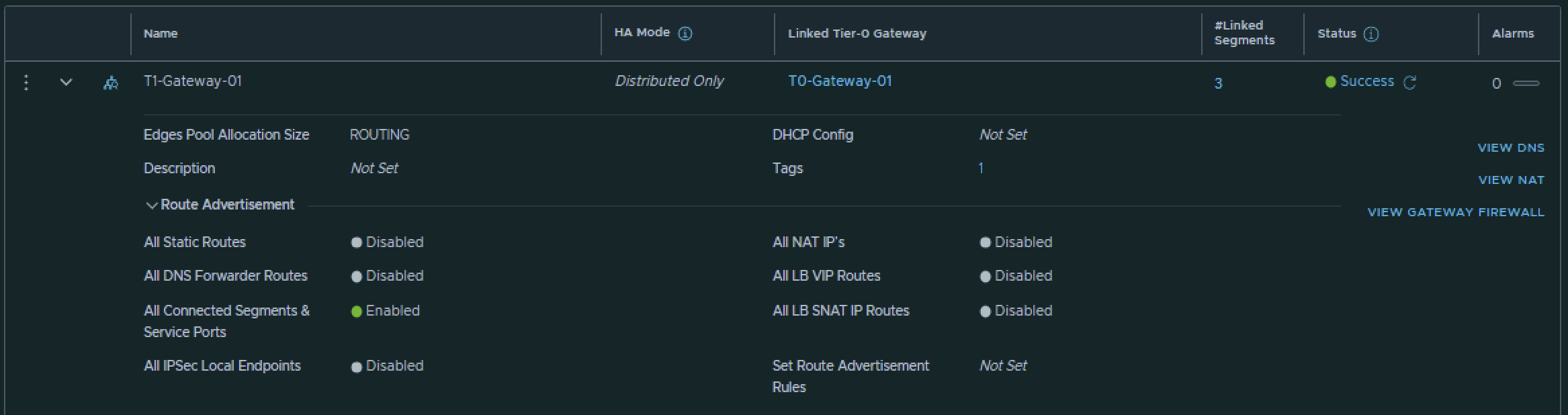
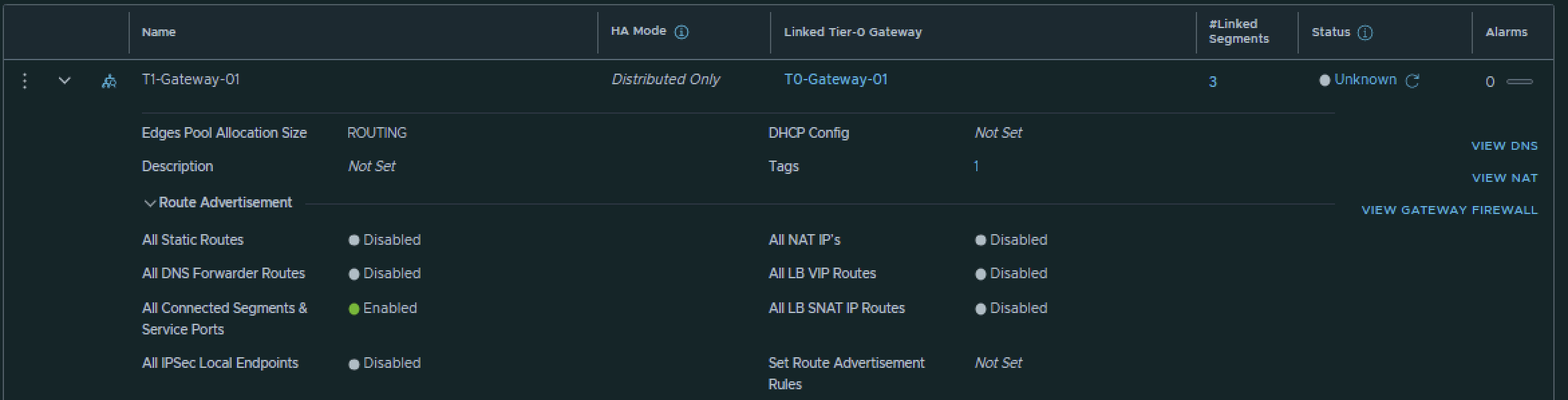
This is the output of the Tier-1 Gateway after I have created it.
Pod 120
I have created the Tier-1 Gateway using the configuration parameters in the table below.
| Name | Linked Tier-0 Gateway |
|---|---|
| T1-Gateway-01 | T0-Gateway-01 |
This is the output of the Tier-1 Gateway after I have created it.
STEP 8» Add IPv6 Web App and DB Segments in NSX
Now that I have created to Tier-1 Gateway and linked the Tier-1 Gateway to the Tier-0 Gateway I am going to create three segments that are going to be linked to the Tier-1 Gateway.
Pod 110
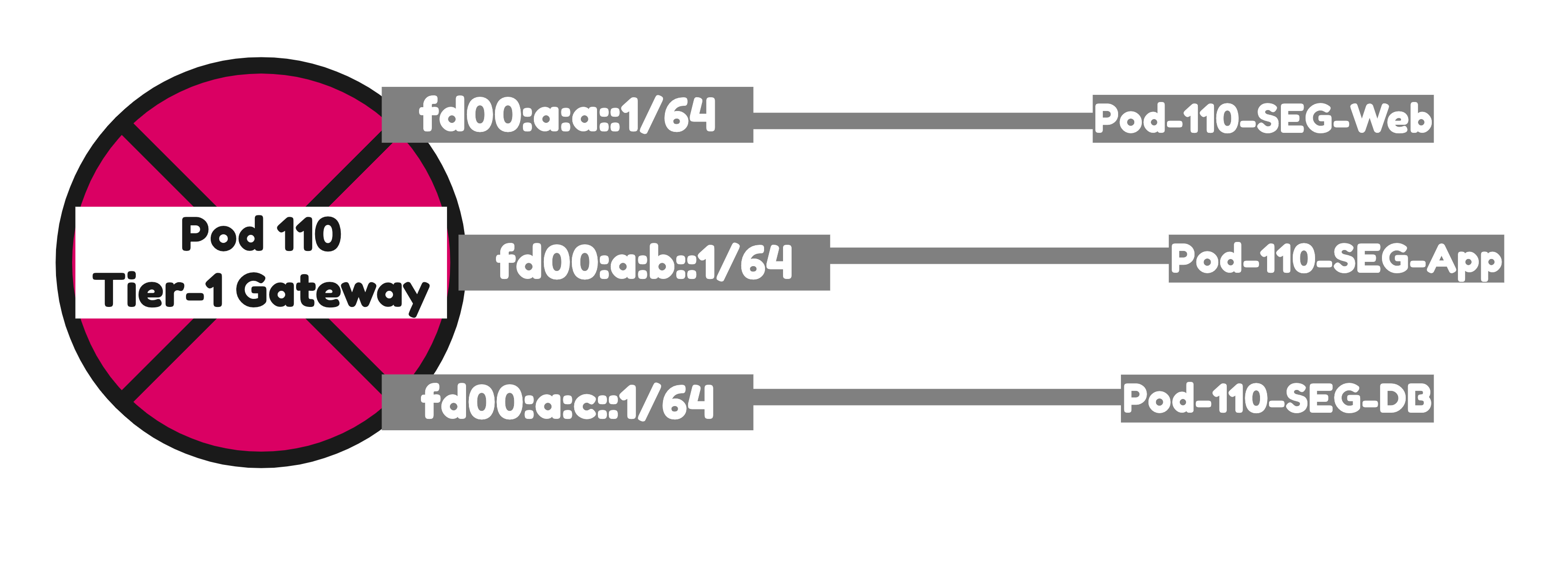
I have created the Segments using the configuration parameters in the table below.
| Segment Name | IPv6 Network | IPv6 T1 Interface address | IPv4 Network | IPv4 T1 Interface address | Transport Zone | Connected Gateway |
|---|---|---|---|---|---|---|
| Pod-110-Web | fd00:a:a::/64 | fd00:a:a::1 | 192.168.1.0/24 | 192.168.1.1 | Overlay | T1-Gateway-01 |
| Pod-110-App | fd00:a:b::/64 | fd00:a:b::1 | 192.168.2.0/24 | 192.168.2.1 | Overlay | T1-Gateway-01 |
| Pod-110-DB | fd00:a:c::/64 | fd00:a:c::1 | 192.168.3.0/24 | 192.168.3.1 | Overlay | T1-Gateway-01 |
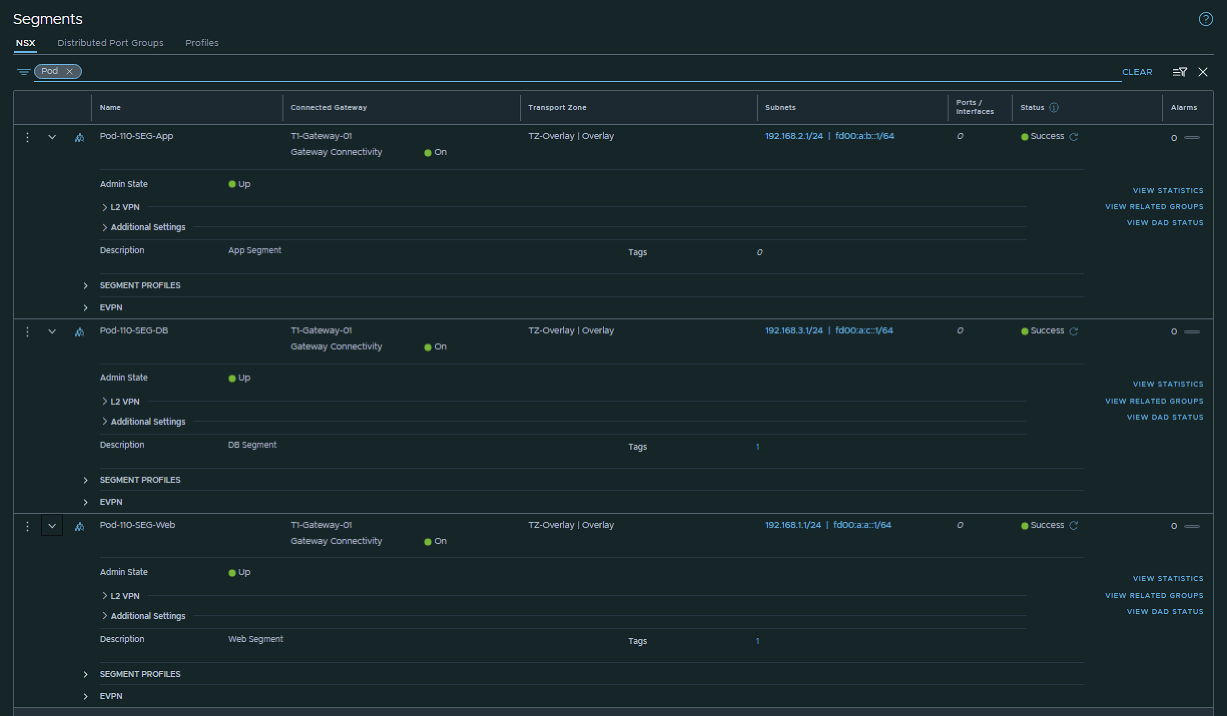
This is the output of all three segments after I have created them.
Pod 120
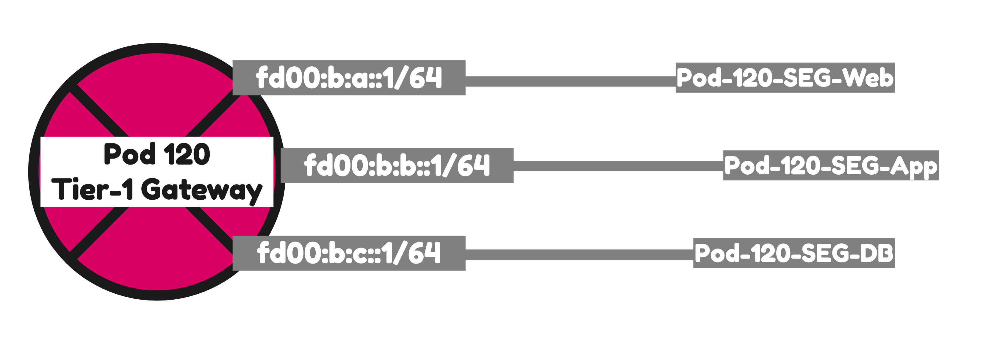
I have created the Segments using the configuration parameters in the table below.
| Segment Name | IPv6 Network | IPv6 T1 Interface address | IPv4 Network | IPv4 T1 Interface address | Transport Zone | Connected Gateway |
|---|---|---|---|---|---|---|
| Pod-120-Web | fd00:b:a::/64 | fd00:b:a::1 | 192.168.5.0/24 | 192.168.5.1 | Overlay | T1-Gateway-01 |
| Pod-120-App | fd00:b:b::/64 | fd00:b:b::1 | 192.168.6.0/24 | 192.168.6.1 | Overlay | T1-Gateway-01 |
| Pod-120-DB | fd00:b:c::/64 | fd00:b:c::1 | 192.168.7.0/24 | 192.168.7.1 | Overlay | T1-Gateway-01 |
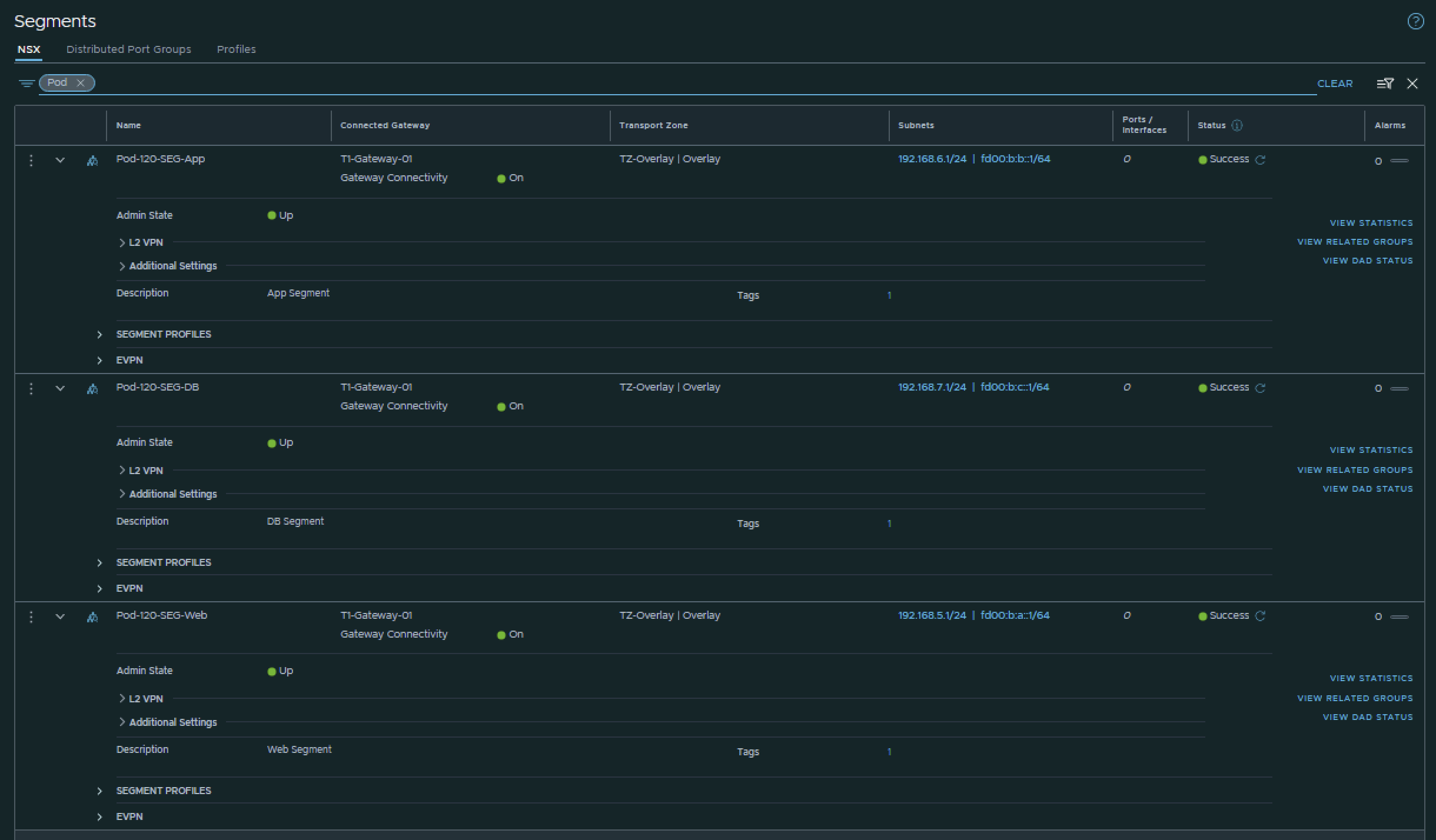
This is the output of all three segments after I have created them.
STEP 9» Configure Route Advertise connected Tier–1 Gateway segment networks to BGP
Now that the Segments are connected to the Tier-1 Gateways both in Pod 110 and Pod 120 these networks need to be advertised into the network so that the Virtual Machines of the Web, App and DB Segment in Pod 110 can reach the Virtual Machines of the Web, App and DB Segment in Pod 120.
Pod 110
T1–Gateway
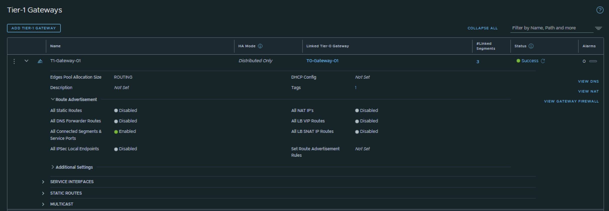
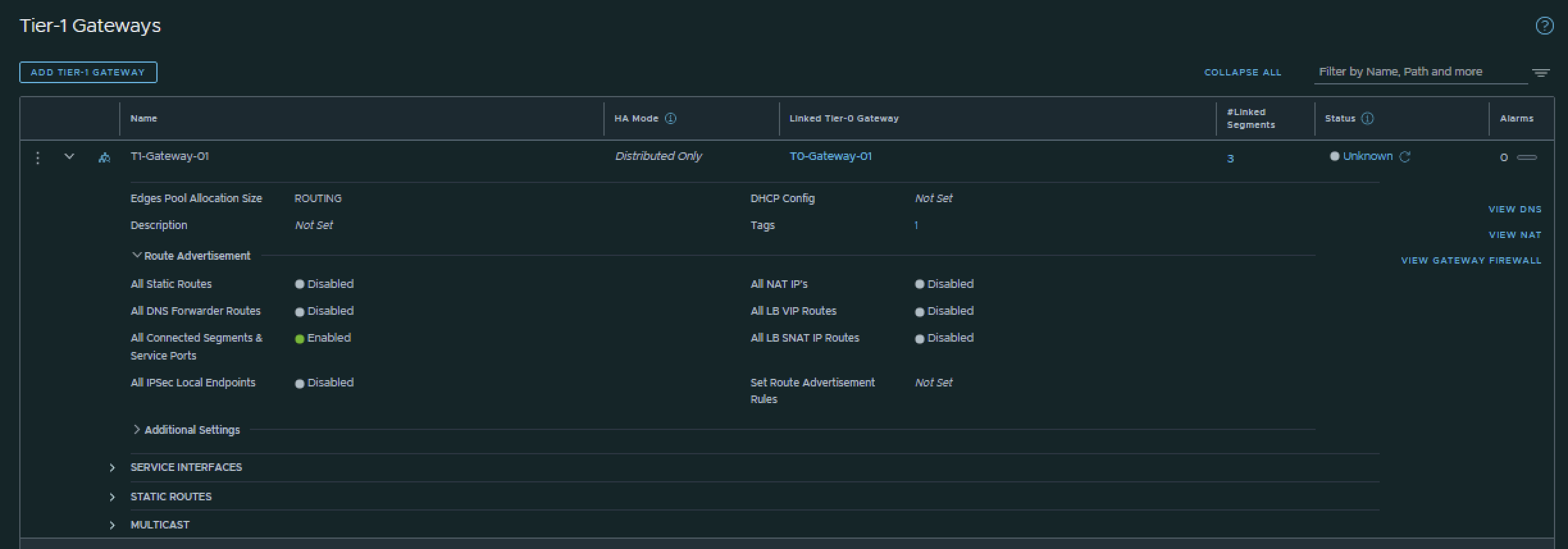
On the Tier-1 Gateway I have enabled Route Advertisement for “All connected Segments & Service Ports”.
T0–Gateway
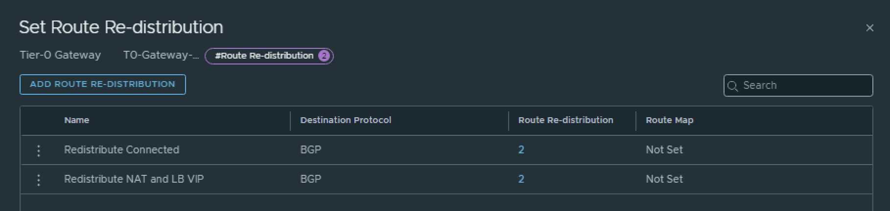
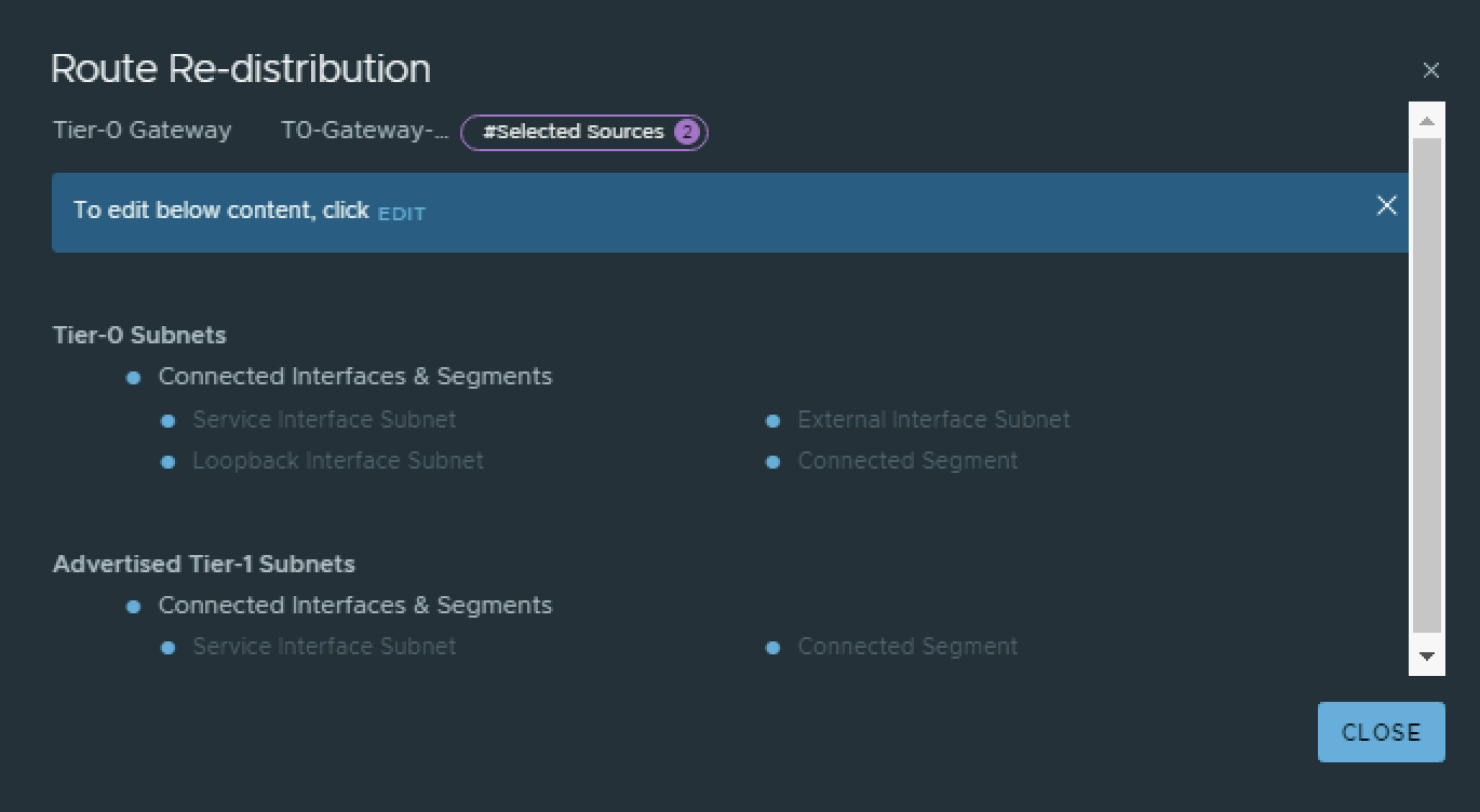
On the Tier-0 Gateway I have enables Route Redistribution so it will Advertise Tier-1 Subnets by enabling “Connected interfaces & Segments”.


Pod 120
T1–Gateway
On the Tier-1 Gateway I have enabled Route Advertisement for “All connected Segments & Service Ports”.
T0–Gateway
On the Tier-0 Gateway I have enables Route Redistribution so it will Advertise Tier-1 Subnets by enabling “Connected interfaces & Segments”.


STEP 10» Configure route redistribution between BGP and OSPFv3
In the previous step we have only enabled that the Web, App and Database are advertised into BGP. But between the Pods OSPFv3 is running.
Pod 110
To redistribute the Networks learned using BGP into OSPF and the other way around I have configured the following commands on the Pod 110 Router.
#
set protocols ospf redistribute bgp
set protocols ospfv3 redistribute bgp
#
Verify Routing
After the redistribution configuration was done I can now see the Pod 120 networks inside my Pod 110 Router and the Pod 110 Tier0 and Tier 1 Gateway.
An output of the routing tables can be found below:
vyos@Pod-110-Router:~$ show ipv6 route
Codes: K - kernel route, C - connected, S - static, R - RIPng,
       O - OSPFv3, I - IS-IS, B - BGP, N - NHRP, T - Table,
       v - VNC, V - VNC-Direct, A - Babel, F - PBR,
       f - OpenFabric,
       > - selected route, * - FIB route, q - queued, r - rejected, b - backup
       t - trapped, o - offload failure

O   fd00::/64 [110/1] is directly connected, eth0, weight 1, 02:06:00
C>* fd00::/64 is directly connected, eth0, 11:40:13
C>* fd00:0:0:6e::/64 is directly connected, eth1.110, 11:40:15
C>* fd00:0:0:6f::/64 is directly connected, eth1.111, 11:40:14
C>* fd00:0:0:70::/64 is directly connected, eth1.112, 11:40:14
C>* fd00:0:0:71::/64 is directly connected, eth1.113, 11:40:15
C>* fd00:0:0:72::/64 is directly connected, eth1.114, 11:40:15
C>* fd00:0:0:73::/64 is directly connected, eth1.115, 11:40:14
B   fd00:0:0:74::/64 [20/0] via fe80::250:56ff:fe9e:1748, eth1.117, weight 1, 09:49:24
                            via fe80::250:56ff:fe9e:60a9, eth1.117, weight 1, 09:49:24
                            via fe80::250:56ff:fe9e:72ee, eth1.116, weight 1, 09:49:24
                            via fe80::250:56ff:fe9e:d5d1, eth1.116, weight 1, 09:49:24
C>* fd00:0:0:74::/64 is directly connected, eth1.116, 11:40:14
B   fd00:0:0:75::/64 [20/0] via fe80::250:56ff:fe9e:1748, eth1.117, weight 1, 09:49:24
                            via fe80::250:56ff:fe9e:60a9, eth1.117, weight 1, 09:49:24
                            via fe80::250:56ff:fe9e:72ee, eth1.116, weight 1, 09:49:24
                            via fe80::250:56ff:fe9e:d5d1, eth1.116, weight 1, 09:49:24
C>* fd00:0:0:75::/64 is directly connected, eth1.117, 11:40:14
C>* fd00:0:0:76::/64 is directly connected, eth1.118, 11:40:13
C>* fd00:0:0:77::/64 is directly connected, eth1.119, 11:40:13
O>* fd00:0:0:78::/64 [110/20] via fe80::20c:29ff:fee3:7976, eth0, weight 1, 02:06:00
O>* fd00:0:0:79::/64 [110/20] via fe80::20c:29ff:fee3:7976, eth0, weight 1, 02:06:00
O>* fd00:0:0:7a::/64 [110/20] via fe80::20c:29ff:fee3:7976, eth0, weight 1, 02:06:00
O>* fd00:0:0:7b::/64 [110/20] via fe80::20c:29ff:fee3:7976, eth0, weight 1, 02:06:00
O>* fd00:0:0:7c::/64 [110/20] via fe80::20c:29ff:fee3:7976, eth0, weight 1, 02:06:00
O>* fd00:0:0:7d::/64 [110/20] via fe80::20c:29ff:fee3:7976, eth0, weight 1, 02:06:00
O>* fd00:0:0:7e::/64 [110/20] via fe80::20c:29ff:fee3:7976, eth0, weight 1, 02:06:00
O>* fd00:0:0:7f::/64 [110/20] via fe80::20c:29ff:fee3:7976, eth0, weight 1, 02:06:00
O>* fd00:0:0:80::/64 [110/20] via fe80::20c:29ff:fee3:7976, eth0, weight 1, 02:06:00
O>* fd00:0:0:81::/64 [110/20] via fe80::20c:29ff:fee3:7976, eth0, weight 1, 02:06:00
O>* fd00:0:0:ffff::/64 [110/20] via fe80::b6fb:e4ff:feca:eb06, eth0, weight 1, 02:06:00
B>* fd00:a:a::/64 [20/0] via fe80::250:56ff:fe9e:1748, eth1.117, weight 1, 09:49:20
  *                      via fe80::250:56ff:fe9e:60a9, eth1.117, weight 1, 09:49:20
  *                      via fe80::250:56ff:fe9e:72ee, eth1.116, weight 1, 09:49:20
  *                      via fe80::250:56ff:fe9e:d5d1, eth1.116, weight 1, 09:49:20
B>* fd00:a:b::/64 [20/0] via fe80::250:56ff:fe9e:1748, eth1.117, weight 1, 09:49:09
  *                      via fe80::250:56ff:fe9e:60a9, eth1.117, weight 1, 09:49:09
  *                      via fe80::250:56ff:fe9e:72ee, eth1.116, weight 1, 09:49:09
  *                      via fe80::250:56ff:fe9e:d5d1, eth1.116, weight 1, 09:49:09
B>* fd00:a:c::/64 [20/0] via fe80::250:56ff:fe9e:1748, eth1.117, weight 1, 09:49:09
  *                      via fe80::250:56ff:fe9e:60a9, eth1.117, weight 1, 09:49:09
  *                      via fe80::250:56ff:fe9e:72ee, eth1.116, weight 1, 09:49:09
  *                      via fe80::250:56ff:fe9e:d5d1, eth1.116, weight 1, 09:49:09
O>* fd00:b:a::/64 [110/20] via fe80::20c:29ff:fee3:7976, eth0, weight 1, 00:01:20
O>* fd00:b:b::/64 [110/20] via fe80::20c:29ff:fee3:7976, eth0, weight 1, 00:01:20
O>* fd00:b:c::/64 [110/20] via fe80::20c:29ff:fee3:7976, eth0, weight 1, 00:01:20
C * fe80::/64 is directly connected, eth1.119, 11:40:13
C * fe80::/64 is directly connected, eth1.117, 11:40:13
C * fe80::/64 is directly connected, eth1.118, 11:40:14
C * fe80::/64 is directly connected, eth1.116, 11:40:14
C * fe80::/64 is directly connected, eth1.115, 11:40:14
C * fe80::/64 is directly connected, eth1.113, 11:40:14
C * fe80::/64 is directly connected, eth1.114, 11:40:14
C * fe80::/64 is directly connected, eth1.110, 11:40:15
C * fe80::/64 is directly connected, eth1.111, 11:40:15
C * fe80::/64 is directly connected, eth1.112, 11:40:15
C * fe80::/64 is directly connected, eth0, 11:42:38
C * fe80::/64 is directly connected, eth1, 11:42:38
C>* fe80::/64 is directly connected, lo, 11:42:39
vyos@Pod-110-Router:~$vyos@Pod-110-Router:~$ show ip route
Codes: K - kernel route, C - connected, S - static, R - RIP,
O - OSPF, I - IS-IS, B - BGP, E - EIGRP, N - NHRP,
T - Table, v - VNC, V - VNC-Direct, A - Babel, F - PBR,
f - OpenFabric,
> - selected route, * - FIB route, q - queued, r - rejected, b - backup
t - trapped, o - offload failure
S>* 0.0.0.0/0 [250/0] via 10.203.0.1, eth0, weight 1, 11:43:14
O>* 10.8.0.0/24 [110/20] via 10.203.0.1, eth0, weight 1, 11:42:37
O>* 10.8.1.0/24 [110/20] via 10.203.0.1, eth0, weight 1, 11:42:37
O>* 10.8.2.0/24 [110/20] via 10.203.0.1, eth0, weight 1, 11:42:37
O>* 10.8.3.0/24 [110/20] via 10.203.0.1, eth0, weight 1, 11:42:37
O>* 10.11.11.0/24 [110/20] via 10.203.0.1, eth0, weight 1, 11:42:37
O>* 10.11.14.0/24 [110/20] via 10.203.0.1, eth0, weight 1, 11:42:37
O>* 10.11.17.0/24 [110/20] via 10.203.0.1, eth0, weight 1, 11:42:37
O>* 10.11.19.0/24 [110/20] via 10.203.0.1, eth0, weight 1, 11:42:37
O>* 10.11.20.0/24 [110/20] via 10.203.0.1, eth0, weight 1, 11:42:37
O>* 10.11.21.0/24 [110/20] via 10.203.0.1, eth0, weight 1, 11:42:37
O>* 10.11.22.0/24 [110/20] via 10.203.0.1, eth0, weight 1, 11:42:37
O>* 10.11.23.0/24 [110/20] via 10.203.0.1, eth0, weight 1, 11:42:37
O>* 10.11.24.0/24 [110/20] via 10.203.0.1, eth0, weight 1, 11:42:37
O>* 10.11.25.0/24 [110/20] via 10.203.0.1, eth0, weight 1, 11:42:37
O>* 10.11.31.0/24 [110/20] via 10.203.0.1, eth0, weight 1, 11:42:37
O>* 10.11.32.0/24 [110/20] via 10.203.0.1, eth0, weight 1, 11:42:37
O>* 10.11.111.0/24 [110/20] via 10.203.0.1, eth0, weight 1, 11:42:37
O 10.203.0.0/24 [110/1] is directly connected, eth0, weight 1, 11:43:19
C>* 10.203.0.0/24 is directly connected, eth0, 11:44:27
C>* 10.203.110.0/24 is directly connected, eth1.110, 11:43:28
C>* 10.203.111.0/24 is directly connected, eth1.111, 11:43:27
C>* 10.203.112.0/24 is directly connected, eth1.112, 11:43:27
C>* 10.203.113.0/24 is directly connected, eth1.113, 11:43:27
C>* 10.203.114.0/24 is directly connected, eth1.114, 11:43:27
C>* 10.203.115.0/24 is directly connected, eth1.115, 11:43:27
B 10.203.116.0/24 [20/0] via 10.203.116.2 inactive, weight 1, 09:52:35
via 10.203.116.3 inactive, weight 1, 09:52:35
via 10.203.117.2, eth1.117, weight 1, 09:52:35
via 10.203.117.3, eth1.117, weight 1, 09:52:35
O 10.203.116.0/24 [110/1] is directly connected, eth1.116, weight 1, 11:43:19
C>* 10.203.116.0/24 is directly connected, eth1.116, 11:43:27
B 10.203.117.0/24 [20/0] via 10.203.116.2, eth1.116, weight 1, 09:52:35
via 10.203.116.3, eth1.116, weight 1, 09:52:35
via 10.203.117.2 inactive, weight 1, 09:52:35
via 10.203.117.3 inactive, weight 1, 09:52:35
O 10.203.117.0/24 [110/1] is directly connected, eth1.117, weight 1, 11:43:19
C>* 10.203.117.0/24 is directly connected, eth1.117, 11:43:26
C>* 10.203.118.0/24 is directly connected, eth1.118, 11:43:26
C>* 10.203.119.0/24 is directly connected, eth1.119, 11:43:26
O>* 10.203.120.0/24 [110/20] via 10.203.0.120, eth0, weight 1, 02:08:52
O>* 10.203.121.0/24 [110/20] via 10.203.0.120, eth0, weight 1, 02:08:52
O>* 10.203.122.0/24 [110/20] via 10.203.0.120, eth0, weight 1, 02:08:52
O>* 10.203.123.0/24 [110/20] via 10.203.0.120, eth0, weight 1, 02:08:52
O>* 10.203.124.0/24 [110/20] via 10.203.0.120, eth0, weight 1, 02:08:52
O>* 10.203.125.0/24 [110/20] via 10.203.0.120, eth0, weight 1, 02:08:52
O>* 10.203.126.0/24 [110/2] via 10.203.0.120, eth0, weight 1, 02:08:53
O>* 10.203.127.0/24 [110/2] via 10.203.0.120, eth0, weight 1, 02:08:53
O>* 10.203.128.0/24 [110/20] via 10.203.0.120, eth0, weight 1, 02:08:52
O>* 10.203.129.0/24 [110/20] via 10.203.0.120, eth0, weight 1, 02:08:52
B>* 192.168.1.0/24 [20/0] via 10.203.116.2, eth1.116, weight 1, 09:52:31
* via 10.203.116.3, eth1.116, weight 1, 09:52:31
* via 10.203.117.2, eth1.117, weight 1, 09:52:31
* via 10.203.117.3, eth1.117, weight 1, 09:52:31
B>* 192.168.2.0/24 [20/0] via 10.203.116.2, eth1.116, weight 1, 09:52:20
* via 10.203.116.3, eth1.116, weight 1, 09:52:20
* via 10.203.117.2, eth1.117, weight 1, 09:52:20
* via 10.203.117.3, eth1.117, weight 1, 09:52:20
B>* 192.168.3.0/24 [20/0] via 10.203.116.2, eth1.116, weight 1, 09:52:20
* via 10.203.116.3, eth1.116, weight 1, 09:52:20
* via 10.203.117.2, eth1.117, weight 1, 09:52:20
* via 10.203.117.3, eth1.117, weight 1, 09:52:20
O>* 192.168.5.0/24 [110/20] via 10.203.0.120, eth0, weight 1, 00:04:31
O>* 192.168.6.0/24 [110/20] via 10.203.0.120, eth0, weight 1, 00:04:31
O>* 192.168.7.0/24 [110/20] via 10.203.0.120, eth0, weight 1, 00:04:31
O>* 192.168.111.0/24 [110/20] via 10.203.0.1, eth0, weight 1, 11:42:37
vyos@Pod-110-Router:~$Pod-110-T0-EdgeVM-01> get logical-router
Wed Aug 31 2022 UTC 21:21:04.286
Logical Router
UUID VRF LR-ID Name Type Ports Neighbors
736a80e3-23f6-5a2d-81d6-bbefb2786666 0 0 TUNNEL 4
4/5000
85cbb437-7eab-41ca-99d8-f06655c1c339 1 1 DR-T0-Gateway-01 DISTRIBUTED_ROUTER_TIER0 5
2/20000
322f1657-3057-44cc-8b32-a947837afbf6 2 2 SR-T0-Gateway-01 SERVICE_ROUTER_TIER0 7
6/20000
23184393-a35e-46df-989c-6af86651f127 4 3 DR-T1-Gateway-01 DISTRIBUTED_ROUTER_TIER1 7
2/20000
Pod-110-T0-EdgeVM-01> vrf 1
Pod-110-T0-EdgeVM-01(vrf[1])> get forwarding
Wed Aug 31 2022 UTC 21:21:31.148
Logical Router
UUID VRF LR-ID Name Type
85cbb437-7eab-41ca-99d8-f06655c1c339 1 1 DR-T0-Gateway-01 DISTRIBUTED_ROUTER_TIER0
IPv4 Forwarding Table
IP Prefix Gateway IP Type UUID Gateway MAC
0.0.0.0/0 10.203.117.1 route cbba506e-bd0c-4ce2-8804-c8bbe285bddb 00:0c:29:f4:7f:1d
10.203.116.1 5740e6e6-f6e7-4124-a71a-09b9137cff05 00:0c:29:f4:7f:1d
10.203.116.0/24 route 5740e6e6-f6e7-4124-a71a-09b9137cff05
10.203.116.2/32 route 5ba3c8c8-d2ef-5c83-a39e-1a431c1f0aac
10.203.116.3/32 169.254.0.131 route f4fab2ff-46bc-4329-a426-70ef4c30b4d1 02:50:56:56:52:02
10.203.117.0/24 route cbba506e-bd0c-4ce2-8804-c8bbe285bddb
10.203.117.2/32 route 5ba3c8c8-d2ef-5c83-a39e-1a431c1f0aac
10.203.117.3/32 169.254.0.131 route f4fab2ff-46bc-4329-a426-70ef4c30b4d1 02:50:56:56:52:02
100.64.0.0/32 route 5a021141-cb97-55d6-ac9e-8aec433dc117
100.64.0.0/31 route 38b49f07-a670-53a7-9532-ef2523ee94a6
127.0.0.1/32 route 89d6dd69-bcb1-4f6f-8bcf-870d38a0dd12
169.254.0.0/25 route 87b65dce-de55-439a-b215-4fa9ba7ea233
169.254.0.1/32 route 5a021141-cb97-55d6-ac9e-8aec433dc117
169.254.0.2/32 route 5ba3c8c8-d2ef-5c83-a39e-1a431c1f0aac
169.254.0.128/25 route f4fab2ff-46bc-4329-a426-70ef4c30b4d1
169.254.0.130/32 route 5ba3c8c8-d2ef-5c83-a39e-1a431c1f0aac
192.168.1.0/24 100.64.0.1 route 38b49f07-a670-53a7-9532-ef2523ee94a6
192.168.2.0/24 100.64.0.1 route 38b49f07-a670-53a7-9532-ef2523ee94a6
192.168.3.0/24 100.64.0.1 route 38b49f07-a670-53a7-9532-ef2523ee94a6
IPv6 Forwarding Table
IP Prefix Gateway IP Type UUID
Gateway MAC
::/0 fe80::20c:29ff:fef4:7f1d route 5740e6e6-f6e7-4124-a71a-09b9137cff05
::1/128 route 89d6dd69-bcb1-4f6f-8bcf-870d38a0dd12
fc3a:f453:da8:9c00::/64 route 38b49f07-a670-53a7-9532-ef2523ee94a6
fc3a:f453:da8:9c00::1/128 route 5a021141-cb97-55d6-ac9e-8aec433dc117
fd00:0:0:74::/64 route 5740e6e6-f6e7-4124-a71a-09b9137cff05
fd00::74:250:56ff:fe9e:d5d1/128 route 5ba3c8c8-d2ef-5c83-a39e-1a431c1f0aac
fd00:0:0:74::3/128 fe80::50:56ff:fe56:5202 route f4fab2ff-46bc-4329-a426-70ef4c30b4d1
fd00::74:250:56ff:fe9e:72ee/128 fe80::50:56ff:fe56:5202 route f4fab2ff-46bc-4329-a426-70ef4c30b4d1
fd00:0:0:74::2/128 route 5ba3c8c8-d2ef-5c83-a39e-1a431c1f0aac
fd00:0:0:75::/64 route cbba506e-bd0c-4ce2-8804-c8bbe285bddb
fd00::75:250:56ff:fe9e:60a9/128 route 5ba3c8c8-d2ef-5c83-a39e-1a431c1f0aac
fd00:0:0:75::3/128 fe80::50:56ff:fe56:5202 route f4fab2ff-46bc-4329-a426-70ef4c30b4d1
fd00::75:250:56ff:fe9e:1748/128 fe80::50:56ff:fe56:5202 route f4fab2ff-46bc-4329-a426-70ef4c30b4d1
fd00:0:0:75::2/128 route 5ba3c8c8-d2ef-5c83-a39e-1a431c1f0aac
fd00:a:a::/64 fc3a:f453:da8:9c00::2 route 38b49f07-a670-53a7-9532-ef2523ee94a6
fd00:a:b::/64 fc3a:f453:da8:9c00::2 route 38b49f07-a670-53a7-9532-ef2523ee94a6
fd00:a:c::/64 fc3a:f453:da8:9c00::2 route 38b49f07-a670-53a7-9532-ef2523ee94a6
Pod-110-T0-EdgeVM-01(vrf[1])>Pod-110-T0-EdgeVM-02> get logical-router
Wed Aug 31 2022 UTC 21:31:33.980
Logical Router
UUID VRF LR-ID Name Type Ports Neighbors
736a80e3-23f6-5a2d-81d6-bbefb2786666 0 0 TUNNEL 4
4/5000
120dbcf7-2d18-4bb6-94a3-b4797adb5b1b 1 8 SR-T0-Gateway-01 SERVICE_ROUTER_TIER0 7
6/20000
85cbb437-7eab-41ca-99d8-f06655c1c339 3 1 DR-T0-Gateway-01 DISTRIBUTED_ROUTER_TIER0 5
2/20000
23184393-a35e-46df-989c-6af86651f127 4 3 DR-T1-Gateway-01 DISTRIBUTED_ROUTER_TIER1 7
2/20000
Pod-110-T0-EdgeVM-02> vrf 3
Pod-110-T0-EdgeVM-02(vrf[3])> get forwarding
Wed Aug 31 2022 UTC 21:32:04.191
Logical Router
UUID VRF LR-ID Name Type
85cbb437-7eab-41ca-99d8-f06655c1c339 3 1 DR-T0-Gateway-01 DISTRIBUTED_ROUTER_TIER0
IPv4 Forwarding Table
IP Prefix Gateway IP Type UUID Gateway MAC
0.0.0.0/0 10.203.117.1 route 21944796-95ae-4037-8f53-c6c104a440e3 00:0c:29:f4:7f:1d
10.203.116.1 450698c4-ecb4-4f70-b4d4-7e447f8694e8 00:0c:29:f4:7f:1d
10.203.116.0/24 route 450698c4-ecb4-4f70-b4d4-7e447f8694e8
10.203.116.2/32 169.254.0.130 route 0eeffa82-94d2-479a-86f3-daddee65c7b0 02:50:56:56:52:01
10.203.116.3/32 route 47aa33ab-f598-58c3-9b4c-c0b5fbbea050
10.203.117.0/24 route 21944796-95ae-4037-8f53-c6c104a440e3
10.203.117.2/32 169.254.0.130 route 0eeffa82-94d2-479a-86f3-daddee65c7b0 02:50:56:56:52:01
10.203.117.3/32 route 47aa33ab-f598-58c3-9b4c-c0b5fbbea050
100.64.0.0/32 route 5a021141-cb97-55d6-ac9e-8aec433dc117
100.64.0.0/31 route 38b49f07-a670-53a7-9532-ef2523ee94a6
127.0.0.1/32 route 89d6dd69-bcb1-4f6f-8bcf-870d38a0dd12
169.254.0.0/25 route 267b98fb-5783-441b-b91f-03c288b2ffd8
169.254.0.1/32 route 5a021141-cb97-55d6-ac9e-8aec433dc117
169.254.0.3/32 route 47aa33ab-f598-58c3-9b4c-c0b5fbbea050
169.254.0.128/25 route 0eeffa82-94d2-479a-86f3-daddee65c7b0
169.254.0.131/32 route 47aa33ab-f598-58c3-9b4c-c0b5fbbea050
192.168.1.0/24 100.64.0.1 route 38b49f07-a670-53a7-9532-ef2523ee94a6
192.168.2.0/24 100.64.0.1 route 38b49f07-a670-53a7-9532-ef2523ee94a6
192.168.3.0/24 100.64.0.1 route 38b49f07-a670-53a7-9532-ef2523ee94a6
IPv6 Forwarding Table
IP Prefix Gateway IP Type UUID
Gateway MAC
::/0 fe80::20c:29ff:fef4:7f1d route 450698c4-ecb4-4f70-b4d4-7e447f8694e8
::1/128 route 89d6dd69-bcb1-4f6f-8bcf-870d38a0dd12
fc3a:f453:da8:9c00::/64 route 38b49f07-a670-53a7-9532-ef2523ee94a6
fc3a:f453:da8:9c00::1/128 route 5a021141-cb97-55d6-ac9e-8aec433dc117
fd00:0:0:74::/64 route 450698c4-ecb4-4f70-b4d4-7e447f8694e8
fd00::74:250:56ff:fe9e:72ee/128 route 47aa33ab-f598-58c3-9b4c-c0b5fbbea050
fd00:0:0:74::2/128 fe80::50:56ff:fe56:5201 route 0eeffa82-94d2-479a-86f3-daddee65c7b0
fd00::74:250:56ff:fe9e:d5d1/128 fe80::50:56ff:fe56:5201 route 0eeffa82-94d2-479a-86f3-daddee65c7b0
fd00:0:0:74::3/128 route 47aa33ab-f598-58c3-9b4c-c0b5fbbea050
fd00:0:0:75::/64 route 21944796-95ae-4037-8f53-c6c104a440e3
fd00:0:0:75::3/128 route 47aa33ab-f598-58c3-9b4c-c0b5fbbea050
fd00:0:0:75::2/128 fe80::50:56ff:fe56:5201 route 0eeffa82-94d2-479a-86f3-daddee65c7b0
fd00::75:250:56ff:fe9e:60a9/128 fe80::50:56ff:fe56:5201 route 0eeffa82-94d2-479a-86f3-daddee65c7b0
fd00::75:250:56ff:fe9e:1748/128 route 47aa33ab-f598-58c3-9b4c-c0b5fbbea050
fd00:a:a::/64 fc3a:f453:da8:9c00::2 route 38b49f07-a670-53a7-9532-ef2523ee94a6
fd00:a:b::/64 fc3a:f453:da8:9c00::2 route 38b49f07-a670-53a7-9532-ef2523ee94a6
fd00:a:c::/64 fc3a:f453:da8:9c00::2 route 38b49f07-a670-53a7-9532-ef2523ee94a6
Pod-110-T0-EdgeVM-02(vrf[3])>Pod-110-T0-EdgeVM-01> get logical-router
Wed Aug 31 2022 UTC 21:33:04.933
Logical Router
UUID VRF LR-ID Name Type Ports Neighbors
736a80e3-23f6-5a2d-81d6-bbefb2786666 0 0 TUNNEL 4
4/5000
85cbb437-7eab-41ca-99d8-f06655c1c339 1 1 DR-T0-Gateway-01 DISTRIBUTED_ROUTER_TIER0 5
2/20000
322f1657-3057-44cc-8b32-a947837afbf6 2 2 SR-T0-Gateway-01 SERVICE_ROUTER_TIER0 7
6/20000
23184393-a35e-46df-989c-6af86651f127 4 3 DR-T1-Gateway-01 DISTRIBUTED_ROUTER_TIER1 7
2/20000
Pod-110-T0-EdgeVM-01> vrf 4
Pod-110-T0-EdgeVM-01(vrf[4])> get forwarding
Wed Aug 31 2022 UTC 21:33:19.176
Logical Router
UUID VRF LR-ID Name Type
23184393-a35e-46df-989c-6af86651f127 4 3 DR-T1-Gateway-01 DISTRIBUTED_ROUTER_TIER1
IPv4 Forwarding Table
IP Prefix Gateway IP Type UUID Gateway MAC
0.0.0.0/0 100.64.0.0 route d02ec573-aa99-4777-983d-16de67c16cde
100.64.0.0/31 route d02ec573-aa99-4777-983d-16de67c16cde
100.64.0.1/32 route 49d24744-e3e9-5f35-9684-4f539a05ebcd
192.168.1.0/24 route 22774d84-817a-4628-be5c-c5bf8d8da884
192.168.1.1/32 route 49d24744-e3e9-5f35-9684-4f539a05ebcd
192.168.2.0/24 route 1535af50-fb99-48ce-b863-9c83c86241f8
192.168.2.1/32 route 49d24744-e3e9-5f35-9684-4f539a05ebcd
192.168.3.0/24 route f46e8977-82b6-4bd0-b9bd-a035ca05f0bd
192.168.3.1/32 route 49d24744-e3e9-5f35-9684-4f539a05ebcd
IPv6 Forwarding Table
IP Prefix Gateway IP Type UUID
Gateway MAC
::/0 fc3a:f453:da8:9c00::1 route d02ec573-aa99-4777-983d-16de67c16cde
fc3a:f453:da8:9c00::/64 route d02ec573-aa99-4777-983d-16de67c16cde
fc3a:f453:da8:9c00::2/128 route 49d24744-e3e9-5f35-9684-4f539a05ebcd
fd00:a:a::/64 route 22774d84-817a-4628-be5c-c5bf8d8da884
fd00:a:a::1/128 route 49d24744-e3e9-5f35-9684-4f539a05ebcd
fd00:a:a:0:50:56ff:fe56:4452/128 route 49d24744-e3e9-5f35-9684-4f539a05ebcd
fd00:a:b::/64 route 1535af50-fb99-48ce-b863-9c83c86241f8
fd00:a:b::1/128 route 49d24744-e3e9-5f35-9684-4f539a05ebcd
fd00:a:b:0:50:56ff:fe56:4452/128 route 49d24744-e3e9-5f35-9684-4f539a05ebcd
fd00:a:c::/64 route f46e8977-82b6-4bd0-b9bd-a035ca05f0bd
fd00:a:c::1/128 route 49d24744-e3e9-5f35-9684-4f539a05ebcd
fd00:a:c:0:50:56ff:fe56:4452/128 route 49d24744-e3e9-5f35-9684-4f539a05ebcd
Pod-110-T0-EdgeVM-01(vrf[4])>Pod-110-T0-EdgeVM-02> get logical-router
Wed Aug 31 2022 UTC 21:33:56.857
Logical Router
UUID VRF LR-ID Name Type Ports Neighbors
736a80e3-23f6-5a2d-81d6-bbefb2786666 0 0 TUNNEL 4
4/5000
120dbcf7-2d18-4bb6-94a3-b4797adb5b1b 1 8 SR-T0-Gateway-01 SERVICE_ROUTER_TIER0 7
6/20000
85cbb437-7eab-41ca-99d8-f06655c1c339 3 1 DR-T0-Gateway-01 DISTRIBUTED_ROUTER_TIER0 5
2/20000
23184393-a35e-46df-989c-6af86651f127 4 3 DR-T1-Gateway-01 DISTRIBUTED_ROUTER_TIER1 7
2/20000
Pod-110-T0-EdgeVM-02> vrf 4
Pod-110-T0-EdgeVM-02(vrf[4])> get forwarding
Wed Aug 31 2022 UTC 21:34:31.912
Logical Router
UUID VRF LR-ID Name Type
23184393-a35e-46df-989c-6af86651f127 4 3 DR-T1-Gateway-01 DISTRIBUTED_ROUTER_TIER1
IPv4 Forwarding Table
IP Prefix Gateway IP Type UUID Gateway MAC
0.0.0.0/0 100.64.0.0 route d02ec573-aa99-4777-983d-16de67c16cde
100.64.0.0/31 route d02ec573-aa99-4777-983d-16de67c16cde
100.64.0.1/32 route 49d24744-e3e9-5f35-9684-4f539a05ebcd
192.168.1.0/24 route 22774d84-817a-4628-be5c-c5bf8d8da884
192.168.1.1/32 route 49d24744-e3e9-5f35-9684-4f539a05ebcd
192.168.2.0/24 route 1535af50-fb99-48ce-b863-9c83c86241f8
192.168.2.1/32 route 49d24744-e3e9-5f35-9684-4f539a05ebcd
192.168.3.0/24 route f46e8977-82b6-4bd0-b9bd-a035ca05f0bd
192.168.3.1/32 route 49d24744-e3e9-5f35-9684-4f539a05ebcd
IPv6 Forwarding Table
IP Prefix Gateway IP Type UUID
Gateway MAC
::/0 fc3a:f453:da8:9c00::1 route d02ec573-aa99-4777-983d-16de67c16cde
fc3a:f453:da8:9c00::/64 route d02ec573-aa99-4777-983d-16de67c16cde
fc3a:f453:da8:9c00::2/128 route 49d24744-e3e9-5f35-9684-4f539a05ebcd
fd00:a:a::/64 route 22774d84-817a-4628-be5c-c5bf8d8da884
fd00:a:a::1/128 route 49d24744-e3e9-5f35-9684-4f539a05ebcd
fd00:a:a:0:50:56ff:fe56:4452/128 route 49d24744-e3e9-5f35-9684-4f539a05ebcd
fd00:a:b::/64 route 1535af50-fb99-48ce-b863-9c83c86241f8
fd00:a:b::1/128 route 49d24744-e3e9-5f35-9684-4f539a05ebcd
fd00:a:b:0:50:56ff:fe56:4452/128 route 49d24744-e3e9-5f35-9684-4f539a05ebcd
fd00:a:c::/64 route f46e8977-82b6-4bd0-b9bd-a035ca05f0bd
fd00:a:c::1/128 route 49d24744-e3e9-5f35-9684-4f539a05ebcd
fd00:a:c:0:50:56ff:fe56:4452/128 route 49d24744-e3e9-5f35-9684-4f539a05ebcd
Pod-110-T0-EdgeVM-02(vrf[4])>
Pod 120
To redistribute the Networks learned using BGP into OSPF and the other way around I have configured the following commands on the Pod 120 Router.
#
set protocols ospf redistribute bgp
set protocols ospfv3 redistribute bgp
#
Verify Routing
After the redistribution configuration was done I can now see the Pod 110 networks inside my Pod 120 Router and the Pod 120 Tier0 and Tier 1 Gateway.
An output of the routing tables can be found below:
vyos@Pod-120-Router:~$ show ipv6 route
Codes: K - kernel route, C - connected, S - static, R - RIPng,
       O - OSPFv3, I - IS-IS, B - BGP, N - NHRP, T - Table,
       v - VNC, V - VNC-Direct, A - Babel, F - PBR,
       f - OpenFabric,
       > - selected route, * - FIB route, q - queued, r - rejected, b - backup
       t - trapped, o - offload failure

O   fd00::/64 [110/1] is directly connected, eth0, weight 1, 02:06:35
C>* fd00::/64 is directly connected, eth0, 02:06:53
O>* fd00:0:0:6e::/64 [110/20] via fe80::20c:29ff:fef4:7f13, eth0, weight 1, 02:06:35
O>* fd00:0:0:6f::/64 [110/20] via fe80::20c:29ff:fef4:7f13, eth0, weight 1, 02:06:35
O>* fd00:0:0:70::/64 [110/20] via fe80::20c:29ff:fef4:7f13, eth0, weight 1, 02:06:35
O>* fd00:0:0:71::/64 [110/20] via fe80::20c:29ff:fef4:7f13, eth0, weight 1, 02:06:35
O>* fd00:0:0:72::/64 [110/20] via fe80::20c:29ff:fef4:7f13, eth0, weight 1, 02:06:35
O>* fd00:0:0:73::/64 [110/20] via fe80::20c:29ff:fef4:7f13, eth0, weight 1, 02:06:35
O>* fd00:0:0:74::/64 [110/20] via fe80::20c:29ff:fef4:7f13, eth0, weight 1, 02:06:35
O>* fd00:0:0:75::/64 [110/20] via fe80::20c:29ff:fef4:7f13, eth0, weight 1, 02:06:35
O>* fd00:0:0:76::/64 [110/20] via fe80::20c:29ff:fef4:7f13, eth0, weight 1, 02:06:35
O>* fd00:0:0:77::/64 [110/20] via fe80::20c:29ff:fef4:7f13, eth0, weight 1, 02:06:35
C>* fd00:0:0:78::/64 is directly connected, eth1.120, 02:06:56
C>* fd00:0:0:79::/64 is directly connected, eth1.121, 02:06:55
C>* fd00:0:0:7a::/64 is directly connected, eth1.122, 02:06:55
C>* fd00:0:0:7b::/64 is directly connected, eth1.123, 02:06:55
C>* fd00:0:0:7c::/64 is directly connected, eth1.124, 02:06:54
C>* fd00:0:0:7d::/64 is directly connected, eth1.125, 02:06:55
B   fd00:0:0:7e::/64 [20/0] via fe80::250:56ff:fe85:ca6, eth1.127, weight 1, 00:01:39
                            via fe80::250:56ff:fe85:46bb, eth1.126, weight 1, 00:01:39
                            via fe80::250:56ff:fe85:7400, eth1.126, weight 1, 00:01:39
                            via fe80::250:56ff:fe85:74ef, eth1.127, weight 1, 00:01:39
C>* fd00:0:0:7e::/64 is directly connected, eth1.126, 02:06:54
B   fd00:0:0:7f::/64 [20/0] via fe80::250:56ff:fe85:ca6, eth1.127, weight 1, 00:01:39
                            via fe80::250:56ff:fe85:46bb, eth1.126, weight 1, 00:01:39
                            via fe80::250:56ff:fe85:7400, eth1.126, weight 1, 00:01:39
                            via fe80::250:56ff:fe85:74ef, eth1.127, weight 1, 00:01:39
C>* fd00:0:0:7f::/64 is directly connected, eth1.127, 02:06:54
C>* fd00:0:0:80::/64 is directly connected, eth1.128, 02:06:54
C>* fd00:0:0:81::/64 is directly connected, eth1.129, 02:06:54
O>* fd00:0:0:ffff::/64 [110/20] via fe80::b6fb:e4ff:feca:eb06, eth0, weight 1, 02:06:35
O>* fd00:a:a::/64 [110/20] via fe80::20c:29ff:fef4:7f13, eth0, weight 1, 02:06:35
O>* fd00:a:b::/64 [110/20] via fe80::20c:29ff:fef4:7f13, eth0, weight 1, 02:06:35
O>* fd00:a:c::/64 [110/20] via fe80::20c:29ff:fef4:7f13, eth0, weight 1, 02:06:35
B>* fd00:b:a::/64 [20/0] via fe80::250:56ff:fe85:ca6, eth1.127, weight 1, 00:01:39
  *                      via fe80::250:56ff:fe85:46bb, eth1.126, weight 1, 00:01:39
  *                      via fe80::250:56ff:fe85:7400, eth1.126, weight 1, 00:01:39
  *                      via fe80::250:56ff:fe85:74ef, eth1.127, weight 1, 00:01:39
B>* fd00:b:b::/64 [20/0] via fe80::250:56ff:fe85:ca6, eth1.127, weight 1, 00:01:39
  *                      via fe80::250:56ff:fe85:46bb, eth1.126, weight 1, 00:01:39
  *                      via fe80::250:56ff:fe85:7400, eth1.126, weight 1, 00:01:39
  *                      via fe80::250:56ff:fe85:74ef, eth1.127, weight 1, 00:01:39
B>* fd00:b:c::/64 [20/0] via fe80::250:56ff:fe85:ca6, eth1.127, weight 1, 00:01:39
  *                      via fe80::250:56ff:fe85:46bb, eth1.126, weight 1, 00:01:39
  *                      via fe80::250:56ff:fe85:7400, eth1.126, weight 1, 00:01:39
  *                      via fe80::250:56ff:fe85:74ef, eth1.127, weight 1, 00:01:39
C * fe80::/64 is directly connected, eth1.129, 02:06:53
C * fe80::/64 is directly connected, eth0, 02:06:54
C * fe80::/64 is directly connected, eth1.128, 02:06:54
C * fe80::/64 is directly connected, eth1.127, 02:06:54
C * fe80::/64 is directly connected, eth1.125, 02:06:54
C * fe80::/64 is directly connected, eth1.126, 02:06:54
C * fe80::/64 is directly connected, eth1.124, 02:06:55
C * fe80::/64 is directly connected, eth1.123, 02:06:55
C * fe80::/64 is directly connected, eth1.121, 02:06:55
C * fe80::/64 is directly connected, eth1.122, 02:06:55
C * fe80::/64 is directly connected, eth1, 02:06:55
C * fe80::/64 is directly connected, eth1.120, 02:06:56
C>* fe80::/64 is directly connected, lo, 02:06:58
vyos@Pod-120-Router:~$vyos@Pod-120-Router:~$ show ip route
Codes: K - kernel route, C - connected, S - static, R - RIP,
O - OSPF, I - IS-IS, B - BGP, E - EIGRP, N - NHRP,
T - Table, v - VNC, V - VNC-Direct, A - Babel, F - PBR,
f - OpenFabric,
> - selected route, * - FIB route, q - queued, r - rejected, b - backup
t - trapped, o - offload failure
S>* 0.0.0.0/0 [250/0] via 10.203.0.1, eth0, weight 1, 02:08:46
O>* 10.8.0.0/24 [110/20] via 10.203.0.1, eth0, weight 1, 02:08:33
O>* 10.8.1.0/24 [110/20] via 10.203.0.1, eth0, weight 1, 02:08:33
O>* 10.8.2.0/24 [110/20] via 10.203.0.1, eth0, weight 1, 02:08:33
O>* 10.8.3.0/24 [110/20] via 10.203.0.1, eth0, weight 1, 02:08:33
O>* 10.11.11.0/24 [110/20] via 10.203.0.1, eth0, weight 1, 02:08:33
O>* 10.11.14.0/24 [110/20] via 10.203.0.1, eth0, weight 1, 02:08:33
O>* 10.11.17.0/24 [110/20] via 10.203.0.1, eth0, weight 1, 02:08:33
O>* 10.11.19.0/24 [110/20] via 10.203.0.1, eth0, weight 1, 02:08:33
O>* 10.11.20.0/24 [110/20] via 10.203.0.1, eth0, weight 1, 02:08:33
O>* 10.11.21.0/24 [110/20] via 10.203.0.1, eth0, weight 1, 02:08:33
O>* 10.11.22.0/24 [110/20] via 10.203.0.1, eth0, weight 1, 02:08:33
O>* 10.11.23.0/24 [110/20] via 10.203.0.1, eth0, weight 1, 02:08:33
O>* 10.11.24.0/24 [110/20] via 10.203.0.1, eth0, weight 1, 02:08:33
O>* 10.11.25.0/24 [110/20] via 10.203.0.1, eth0, weight 1, 02:08:33
O>* 10.11.31.0/24 [110/20] via 10.203.0.1, eth0, weight 1, 02:08:33
O>* 10.11.32.0/24 [110/20] via 10.203.0.1, eth0, weight 1, 02:08:33
O>* 10.11.111.0/24 [110/20] via 10.203.0.1, eth0, weight 1, 02:08:33
O 10.203.0.0/24 [110/1] is directly connected, eth0, weight 1, 02:08:51
C>* 10.203.0.0/24 is directly connected, eth0, 02:09:02
O>* 10.203.110.0/24 [110/20] via 10.203.0.110, eth0, weight 1, 02:08:33
O>* 10.203.111.0/24 [110/20] via 10.203.0.110, eth0, weight 1, 02:08:33
O>* 10.203.112.0/24 [110/20] via 10.203.0.110, eth0, weight 1, 02:08:33
O>* 10.203.113.0/24 [110/20] via 10.203.0.110, eth0, weight 1, 02:08:33
O>* 10.203.114.0/24 [110/20] via 10.203.0.110, eth0, weight 1, 02:08:33
O>* 10.203.115.0/24 [110/20] via 10.203.0.110, eth0, weight 1, 02:08:33
O>* 10.203.116.0/24 [110/2] via 10.203.0.110, eth0, weight 1, 02:08:34
O>* 10.203.117.0/24 [110/2] via 10.203.0.110, eth0, weight 1, 02:08:34
O>* 10.203.118.0/24 [110/20] via 10.203.0.110, eth0, weight 1, 02:08:33
O>* 10.203.119.0/24 [110/20] via 10.203.0.110, eth0, weight 1, 02:08:33
C>* 10.203.120.0/24 is directly connected, eth1.120, 02:09:04
C>* 10.203.121.0/24 is directly connected, eth1.121, 02:09:04
C>* 10.203.122.0/24 is directly connected, eth1.122, 02:09:03
C>* 10.203.123.0/24 is directly connected, eth1.123, 02:09:03
C>* 10.203.124.0/24 is directly connected, eth1.124, 02:09:03
C>* 10.203.125.0/24 is directly connected, eth1.125, 02:09:03
B 10.203.126.0/24 [20/0] via 10.203.126.2 inactive, weight 1, 00:03:46
via 10.203.126.3 inactive, weight 1, 00:03:46
via 10.203.127.2, eth1.127, weight 1, 00:03:46
via 10.203.127.3, eth1.127, weight 1, 00:03:46
O 10.203.126.0/24 [110/1] is directly connected, eth1.126, weight 1, 02:08:51
C>* 10.203.126.0/24 is directly connected, eth1.126, 02:09:03
B 10.203.127.0/24 [20/0] via 10.203.126.2, eth1.126, weight 1, 00:03:46
via 10.203.126.3, eth1.126, weight 1, 00:03:46
via 10.203.127.2 inactive, weight 1, 00:03:46
via 10.203.127.3 inactive, weight 1, 00:03:46
O 10.203.127.0/24 [110/1] is directly connected, eth1.127, weight 1, 02:08:51
C>* 10.203.127.0/24 is directly connected, eth1.127, 02:09:03
C>* 10.203.128.0/24 is directly connected, eth1.128, 02:09:02
C>* 10.203.129.0/24 is directly connected, eth1.129, 02:09:02
O>* 192.168.1.0/24 [110/20] via 10.203.0.110, eth0, weight 1, 02:08:33
O>* 192.168.2.0/24 [110/20] via 10.203.0.110, eth0, weight 1, 02:08:33
O>* 192.168.3.0/24 [110/20] via 10.203.0.110, eth0, weight 1, 02:08:33
B>* 192.168.5.0/24 [20/0] via 10.203.126.2, eth1.126, weight 1, 00:03:46
* via 10.203.126.3, eth1.126, weight 1, 00:03:46
* via 10.203.127.2, eth1.127, weight 1, 00:03:46
* via 10.203.127.3, eth1.127, weight 1, 00:03:46
B>* 192.168.6.0/24 [20/0] via 10.203.126.2, eth1.126, weight 1, 00:03:46
* via 10.203.126.3, eth1.126, weight 1, 00:03:46
* via 10.203.127.2, eth1.127, weight 1, 00:03:46
* via 10.203.127.3, eth1.127, weight 1, 00:03:46
B>* 192.168.7.0/24 [20/0] via 10.203.126.2, eth1.126, weight 1, 00:03:46
* via 10.203.126.3, eth1.126, weight 1, 00:03:46
* via 10.203.127.2, eth1.127, weight 1, 00:03:46
* via 10.203.127.3, eth1.127, weight 1, 00:03:46
O>* 192.168.111.0/24 [110/20] via 10.203.0.1, eth0, weight 1, 02:08:33
vyos@Pod-120-Router:~$Pod-120-T0-EdgeVM-01> get logical-router
Wed Aug 31 2022 UTC 21:36:18.561
Logical Router
UUID VRF LR-ID Name Type Ports Neighbors
736a80e3-23f6-5a2d-81d6-bbefb2786666 0 0 TUNNEL 4
4/5000
e011df91-bfbc-46d4-8f8a-adbcc2b241d6 1 1 DR-T0-Gateway-01 DISTRIBUTED_ROUTER_TIER0 5
2/20000
06668568-786e-4b5c-8f99-0ff0799c7c9f 2 14 DR-T1-Gateway-01 DISTRIBUTED_ROUTER_TIER1 7
2/20000
157da70b-9636-4163-b175-35e8f7535637 3 2 SR-T0-Gateway-01 SERVICE_ROUTER_TIER0 7
6/20000
Pod-120-T0-EdgeVM-01> vrf 1
Pod-120-T0-EdgeVM-01(vrf[1])> get forwarding
Wed Aug 31 2022 UTC 21:36:32.331
Logical Router
UUID VRF LR-ID Name Type
e011df91-bfbc-46d4-8f8a-adbcc2b241d6 1 1 DR-T0-Gateway-01 DISTRIBUTED_ROUTER_TIER0
IPv4 Forwarding Table
IP Prefix Gateway IP Type UUID Gateway MAC
0.0.0.0/0 10.203.127.1 route 8026e680-ed7d-4309-bed3-ce5513000c2b 00:0c:29:e3:79:80
10.203.126.1 939f4c23-49c5-4bca-be16-41415075316a 00:0c:29:e3:79:80
10.203.126.0/24 route 939f4c23-49c5-4bca-be16-41415075316a
10.203.126.2/32 route 797e16bb-fcad-5d2b-99aa-652618c4fc95
10.203.126.3/32 169.254.0.131 route fbd9c0bd-3d7a-443c-9794-d738aa8b69a5 02:50:56:56:52:02
10.203.127.0/24 route 8026e680-ed7d-4309-bed3-ce5513000c2b
10.203.127.2/32 route 797e16bb-fcad-5d2b-99aa-652618c4fc95
10.203.127.3/32 169.254.0.131 route fbd9c0bd-3d7a-443c-9794-d738aa8b69a5 02:50:56:56:52:02
100.64.0.0/32 route af741b72-6e71-56b0-b168-d243a06a3a6e
100.64.0.0/31 route 38b49f07-a670-53a7-9532-ef2523ee94a6
127.0.0.1/32 route 968b4759-518b-434f-8958-eb06548ec3b0
169.254.0.0/25 route 7ac0afcd-108a-4021-a8ce-0a72a9269f1a
169.254.0.1/32 route af741b72-6e71-56b0-b168-d243a06a3a6e
169.254.0.2/32 route 797e16bb-fcad-5d2b-99aa-652618c4fc95
169.254.0.128/25 route fbd9c0bd-3d7a-443c-9794-d738aa8b69a5
169.254.0.130/32 route 797e16bb-fcad-5d2b-99aa-652618c4fc95
192.168.5.0/24 100.64.0.1 route 38b49f07-a670-53a7-9532-ef2523ee94a6 02:50:56:56:44:55
192.168.6.0/24 100.64.0.1 route 38b49f07-a670-53a7-9532-ef2523ee94a6 02:50:56:56:44:55
192.168.7.0/24 100.64.0.1 route 38b49f07-a670-53a7-9532-ef2523ee94a6 02:50:56:56:44:55
IPv6 Forwarding Table
IP Prefix Gateway IP Type UUID
Gateway MAC
::/0 fe80::20c:29ff:fee3:7980 route 939f4c23-49c5-4bca-be16-41415075316a
::1/128 route 968b4759-518b-434f-8958-eb06548ec3b0
fcb2:6604:2741:3c00::/64 route 38b49f07-a670-53a7-9532-ef2523ee94a6
fcb2:6604:2741:3c00::1/128 route af741b72-6e71-56b0-b168-d243a06a3a6e
fd00:0:0:7e::/64 route 939f4c23-49c5-4bca-be16-41415075316a
fd00::7e:250:56ff:fe85:46bb/128 route 797e16bb-fcad-5d2b-99aa-652618c4fc95
fd00:0:0:7e::3/128 fe80::50:56ff:fe56:5202 route fbd9c0bd-3d7a-443c-9794-d738aa8b69a5
fd00::7e:250:56ff:fe85:7400/128 fe80::50:56ff:fe56:5202 route fbd9c0bd-3d7a-443c-9794-d738aa8b69a5
fd00:0:0:7e::2/128 route 797e16bb-fcad-5d2b-99aa-652618c4fc95
fd00:0:0:7f::/64 route 8026e680-ed7d-4309-bed3-ce5513000c2b
fd00:0:0:7f::2/128 route 797e16bb-fcad-5d2b-99aa-652618c4fc95
fd00:0:0:7f::3/128 fe80::50:56ff:fe56:5202 route fbd9c0bd-3d7a-443c-9794-d738aa8b69a5
fd00::7f:250:56ff:fe85:ca6/128 fe80::50:56ff:fe56:5202 route fbd9c0bd-3d7a-443c-9794-d738aa8b69a5
fd00::7f:250:56ff:fe85:74ef/128 route 797e16bb-fcad-5d2b-99aa-652618c4fc95
fd00:b:a::/64 fcb2:6604:2741:3c00::2 route 38b49f07-a670-53a7-9532-ef2523ee94a6 02:50:56:56:44:55
fd00:b:b::/64 fcb2:6604:2741:3c00::2 route 38b49f07-a670-53a7-9532-ef2523ee94a6 02:50:56:56:44:55
fd00:b:c::/64 fcb2:6604:2741:3c00::2 route 38b49f07-a670-53a7-9532-ef2523ee94a6 02:50:56:56:44:55
Pod-120-T0-EdgeVM-01(vrf[1])>Pod-120-T0-EdgeVM-02> get logical-router
Wed Aug 31 2022 UTC 21:37:24.788
Logical Router
UUID VRF LR-ID Name Type Ports Neighbors
736a80e3-23f6-5a2d-81d6-bbefb2786666 0 0 TUNNEL 4
4/5000
e011df91-bfbc-46d4-8f8a-adbcc2b241d6 1 1 DR-T0-Gateway-01 DISTRIBUTED_ROUTER_TIER0 5
2/20000
06668568-786e-4b5c-8f99-0ff0799c7c9f 2 14 DR-T1-Gateway-01 DISTRIBUTED_ROUTER_TIER1 7
2/20000
9ec0f75a-5f89-4551-9462-96de69c6a38f 3 7 SR-T0-Gateway-01 SERVICE_ROUTER_TIER0 7
6/20000
Pod-120-T0-EdgeVM-02> vrf 1
Pod-120-T0-EdgeVM-02(vrf[1])> get forwarding
Wed Aug 31 2022 UTC 21:37:35.783
Logical Router
UUID VRF LR-ID Name Type
e011df91-bfbc-46d4-8f8a-adbcc2b241d6 1 1 DR-T0-Gateway-01 DISTRIBUTED_ROUTER_TIER0
IPv4 Forwarding Table
IP Prefix Gateway IP Type UUID Gateway MAC
0.0.0.0/0 10.203.127.1 route 84a805c2-1f91-4d0a-ba2d-c7f6914359bd 00:0c:29:e3:79:80
10.203.126.1 de701600-4ebf-4665-bd87-e96de8a0837c 00:0c:29:e3:79:80
10.203.126.0/24 route de701600-4ebf-4665-bd87-e96de8a0837c
10.203.126.2/32 169.254.0.130 route 2aaca363-d724-4c20-a89e-b8f74798c66a 02:50:56:56:52:01
10.203.126.3/32 route f882f148-e176-51ac-b2a5-2dbe9f5783e6
10.203.127.0/24 route 84a805c2-1f91-4d0a-ba2d-c7f6914359bd
10.203.127.2/32 169.254.0.130 route 2aaca363-d724-4c20-a89e-b8f74798c66a 02:50:56:56:52:01
10.203.127.3/32 route f882f148-e176-51ac-b2a5-2dbe9f5783e6
100.64.0.0/32 route af741b72-6e71-56b0-b168-d243a06a3a6e
100.64.0.0/31 route 38b49f07-a670-53a7-9532-ef2523ee94a6
127.0.0.1/32 route 968b4759-518b-434f-8958-eb06548ec3b0
169.254.0.0/25 route d1175ce3-cd04-4a3c-8a6e-ff8f3626e0c8
169.254.0.1/32 route af741b72-6e71-56b0-b168-d243a06a3a6e
169.254.0.3/32 route f882f148-e176-51ac-b2a5-2dbe9f5783e6
169.254.0.128/25 route 2aaca363-d724-4c20-a89e-b8f74798c66a
169.254.0.131/32 route f882f148-e176-51ac-b2a5-2dbe9f5783e6
192.168.5.0/24 100.64.0.1 route 38b49f07-a670-53a7-9532-ef2523ee94a6
192.168.6.0/24 100.64.0.1 route 38b49f07-a670-53a7-9532-ef2523ee94a6
192.168.7.0/24 100.64.0.1 route 38b49f07-a670-53a7-9532-ef2523ee94a6
IPv6 Forwarding Table
IP Prefix Gateway IP Type UUID
Gateway MAC
::/0 fe80::20c:29ff:fee3:7980 route de701600-4ebf-4665-bd87-e96de8a0837c
::1/128 route 968b4759-518b-434f-8958-eb06548ec3b0
fcb2:6604:2741:3c00::/64 route 38b49f07-a670-53a7-9532-ef2523ee94a6
fcb2:6604:2741:3c00::1/128 route af741b72-6e71-56b0-b168-d243a06a3a6e
fd00:0:0:7e::/64 route de701600-4ebf-4665-bd87-e96de8a0837c
fd00:0:0:7e::3/128 route f882f148-e176-51ac-b2a5-2dbe9f5783e6
fd00:0:0:7e::2/128 fe80::50:56ff:fe56:5201 route 2aaca363-d724-4c20-a89e-b8f74798c66a
fd00::7e:250:56ff:fe85:46bb/128 fe80::50:56ff:fe56:5201 route 2aaca363-d724-4c20-a89e-b8f74798c66a
fd00::7e:250:56ff:fe85:7400/128 route f882f148-e176-51ac-b2a5-2dbe9f5783e6
fd00:0:0:7f::/64 route 84a805c2-1f91-4d0a-ba2d-c7f6914359bd
fd00::7f:250:56ff:fe85:ca6/128 route f882f148-e176-51ac-b2a5-2dbe9f5783e6
fd00::7f:250:56ff:fe85:74ef/128 fe80::50:56ff:fe56:5201 route 2aaca363-d724-4c20-a89e-b8f74798c66a
fd00:0:0:7f::2/128 fe80::50:56ff:fe56:5201 route 2aaca363-d724-4c20-a89e-b8f74798c66a
fd00:0:0:7f::3/128 route f882f148-e176-51ac-b2a5-2dbe9f5783e6
fd00:b:a::/64 fcb2:6604:2741:3c00::2 route 38b49f07-a670-53a7-9532-ef2523ee94a6
fd00:b:b::/64 fcb2:6604:2741:3c00::2 route 38b49f07-a670-53a7-9532-ef2523ee94a6
fd00:b:c::/64 fcb2:6604:2741:3c00::2 route 38b49f07-a670-53a7-9532-ef2523ee94a6
Pod-120-T0-EdgeVM-02(vrf[1])>Pod-120-T0-EdgeVM-01> get logical-router
Wed Aug 31 2022 UTC 21:39:16.632
Logical Router
UUID VRF LR-ID Name Type Ports Neighbors
736a80e3-23f6-5a2d-81d6-bbefb2786666 0 0 TUNNEL 4
4/5000
e011df91-bfbc-46d4-8f8a-adbcc2b241d6 1 1 DR-T0-Gateway-01 DISTRIBUTED_ROUTER_TIER0 5
2/20000
06668568-786e-4b5c-8f99-0ff0799c7c9f 2 14 DR-T1-Gateway-01 DISTRIBUTED_ROUTER_TIER1 7
2/20000
157da70b-9636-4163-b175-35e8f7535637 3 2 SR-T0-Gateway-01 SERVICE_ROUTER_TIER0 7
6/20000
Pod-120-T0-EdgeVM-01> vrf 2
Pod-120-T0-EdgeVM-01(vrf[2])> get forwarding
Wed Aug 31 2022 UTC 21:39:31.219
Logical Router
UUID VRF LR-ID Name Type
06668568-786e-4b5c-8f99-0ff0799c7c9f 2 14 DR-T1-Gateway-01 DISTRIBUTED_ROUTER_TIER1
IPv4 Forwarding Table
IP Prefix Gateway IP Type UUID Gateway MAC
0.0.0.0/0 100.64.0.0 route 9dcf9726-5160-4b17-9d48-d8d0c97da2ba 02:50:56:56:44:52
100.64.0.0/31 route 9dcf9726-5160-4b17-9d48-d8d0c97da2ba
100.64.0.1/32 route e2a59281-05b0-5701-a43f-bf44baf675d0
192.168.5.0/24 route c8cca3a7-5cd8-4071-8963-99d796846834
192.168.5.1/32 route e2a59281-05b0-5701-a43f-bf44baf675d0
192.168.6.0/24 route 9dfb3ada-86b4-489d-ae63-bcfcf7eb37e8
192.168.6.1/32 route e2a59281-05b0-5701-a43f-bf44baf675d0
192.168.7.0/24 route b74edb96-54a5-4802-a822-9dad58d872e6
192.168.7.1/32 route e2a59281-05b0-5701-a43f-bf44baf675d0
IPv6 Forwarding Table
IP Prefix Gateway IP Type UUID
Gateway MAC
::/0 fcb2:6604:2741:3c00::1 route 9dcf9726-5160-4b17-9d48-d8d0c97da2ba 02:50:56:56:44:52
fcb2:6604:2741:3c00::/64 route 9dcf9726-5160-4b17-9d48-d8d0c97da2ba
fcb2:6604:2741:3c00::2/128 route e2a59281-05b0-5701-a43f-bf44baf675d0
fd00:b:a::/64 route c8cca3a7-5cd8-4071-8963-99d796846834
fd00:b:a:0:50:56ff:fe56:4452/128 route e2a59281-05b0-5701-a43f-bf44baf675d0
fd00:b:a::1/128 route e2a59281-05b0-5701-a43f-bf44baf675d0
fd00:b:b::/64 route 9dfb3ada-86b4-489d-ae63-bcfcf7eb37e8
fd00:b:b::1/128 route e2a59281-05b0-5701-a43f-bf44baf675d0
fd00:b:b:0:50:56ff:fe56:4452/128 route e2a59281-05b0-5701-a43f-bf44baf675d0
fd00:b:c::/64 route b74edb96-54a5-4802-a822-9dad58d872e6
fd00:b:c::1/128 route e2a59281-05b0-5701-a43f-bf44baf675d0
fd00:b:c:0:50:56ff:fe56:4452/128 route e2a59281-05b0-5701-a43f-bf44baf675d0
Pod-120-T0-EdgeVM-01(vrf[2])>Pod-120-T0-EdgeVM-02> get logical-router
Wed Aug 31 2022 UTC 21:40:14.160
Logical Router
UUID VRF LR-ID Name Type Ports Neighbors
736a80e3-23f6-5a2d-81d6-bbefb2786666 0 0 TUNNEL 4
4/5000
e011df91-bfbc-46d4-8f8a-adbcc2b241d6 1 1 DR-T0-Gateway-01 DISTRIBUTED_ROUTER_TIER0 5
2/20000
06668568-786e-4b5c-8f99-0ff0799c7c9f 2 14 DR-T1-Gateway-01 DISTRIBUTED_ROUTER_TIER1 7
2/20000
9ec0f75a-5f89-4551-9462-96de69c6a38f 3 7 SR-T0-Gateway-01 SERVICE_ROUTER_TIER0 7
6/20000
Pod-120-T0-EdgeVM-02> vrf 2
Pod-120-T0-EdgeVM-02(vrf[2])> get forwarding
Wed Aug 31 2022 UTC 21:40:24.174
Logical Router
UUID VRF LR-ID Name Type
06668568-786e-4b5c-8f99-0ff0799c7c9f 2 14 DR-T1-Gateway-01 DISTRIBUTED_ROUTER_TIER1
IPv4 Forwarding Table
IP Prefix Gateway IP Type UUID Gateway MAC
0.0.0.0/0 100.64.0.0 route 9dcf9726-5160-4b17-9d48-d8d0c97da2ba
100.64.0.0/31 route 9dcf9726-5160-4b17-9d48-d8d0c97da2ba
100.64.0.1/32 route e2a59281-05b0-5701-a43f-bf44baf675d0
192.168.5.0/24 route c8cca3a7-5cd8-4071-8963-99d796846834
192.168.5.1/32 route e2a59281-05b0-5701-a43f-bf44baf675d0
192.168.6.0/24 route 9dfb3ada-86b4-489d-ae63-bcfcf7eb37e8
192.168.6.1/32 route e2a59281-05b0-5701-a43f-bf44baf675d0
192.168.7.0/24 route b74edb96-54a5-4802-a822-9dad58d872e6
192.168.7.1/32 route e2a59281-05b0-5701-a43f-bf44baf675d0
IPv6 Forwarding Table
IP Prefix Gateway IP Type UUID
Gateway MAC
::/0 fcb2:6604:2741:3c00::1 route 9dcf9726-5160-4b17-9d48-d8d0c97da2ba
fcb2:6604:2741:3c00::/64 route 9dcf9726-5160-4b17-9d48-d8d0c97da2ba
fcb2:6604:2741:3c00::2/128 route e2a59281-05b0-5701-a43f-bf44baf675d0
fd00:b:a::/64 route c8cca3a7-5cd8-4071-8963-99d796846834
fd00:b:a:0:50:56ff:fe56:4452/128 route e2a59281-05b0-5701-a43f-bf44baf675d0
fd00:b:a::1/128 route e2a59281-05b0-5701-a43f-bf44baf675d0
fd00:b:b::/64 route 9dfb3ada-86b4-489d-ae63-bcfcf7eb37e8
fd00:b:b::1/128 route e2a59281-05b0-5701-a43f-bf44baf675d0
fd00:b:b:0:50:56ff:fe56:4452/128 route e2a59281-05b0-5701-a43f-bf44baf675d0
fd00:b:c::/64 route b74edb96-54a5-4802-a822-9dad58d872e6
fd00:b:c::1/128 route e2a59281-05b0-5701-a43f-bf44baf675d0
fd00:b:c:0:50:56ff:fe56:4452/128 route e2a59281-05b0-5701-a43f-bf44baf675d0
Pod-120-T0-EdgeVM-02(vrf[2])>
WAN
The WAN Gateway also learns all the routes that are coming from Pod 110 and Pod 120.
Verify Routing
An output of the routing tables can be found below:
ubnt@ubnt:~$ show ipv6 route
IPv6 Routing Table
Codes: K - kernel route, C - connected, S - static, R - RIP, O - OSPF,
       IA - OSPF inter area, E1 - OSPF external type 1,
       E2 - OSPF external type 2, N1 - OSPF NSSA external type 1,
       N2 - OSPF NSSA external type 2, B - BGP
Timers: Uptime

IP Route Table for VRF "default"
C      ::1/128 via ::, lo, 18w1d16h
C      fd00::/64 via ::, eth1.203, 3d08h25m
O E2   fd00::6e:0:0:0:0/64 [110/20] via fe80::20c:29ff:fef4:7f13, eth1.203, 11:41:37
O E2   fd00::6f:0:0:0:0/64 [110/20] via fe80::20c:29ff:fef4:7f13, eth1.203, 11:41:37
O E2   fd00::70:0:0:0:0/64 [110/20] via fe80::20c:29ff:fef4:7f13, eth1.203, 11:41:37
O E2   fd00::71:0:0:0:0/64 [110/20] via fe80::20c:29ff:fef4:7f13, eth1.203, 11:41:37
O E2   fd00::72:0:0:0:0/64 [110/20] via fe80::20c:29ff:fef4:7f13, eth1.203, 11:41:37
O E2   fd00::73:0:0:0:0/64 [110/20] via fe80::20c:29ff:fef4:7f13, eth1.203, 11:41:37
O E2   fd00::74:0:0:0:0/64 [110/20] via fe80::20c:29ff:fef4:7f13, eth1.203, 11:41:37
O E2   fd00::75:0:0:0:0/64 [110/20] via fe80::20c:29ff:fef4:7f13, eth1.203, 11:41:37
O E2   fd00::76:0:0:0:0/64 [110/20] via fe80::20c:29ff:fef4:7f13, eth1.203, 11:41:37
O E2   fd00::77:0:0:0:0/64 [110/20] via fe80::20c:29ff:fef4:7f13, eth1.203, 11:41:37
O E2   fd00::78:0:0:0:0/64 [110/20] via fe80::20c:29ff:fee3:7976, eth1.203, 02:07:39
O E2   fd00::79:0:0:0:0/64 [110/20] via fe80::20c:29ff:fee3:7976, eth1.203, 02:07:39
O E2   fd00::7a:0:0:0:0/64 [110/20] via fe80::20c:29ff:fee3:7976, eth1.203, 02:07:39
O E2   fd00::7b:0:0:0:0/64 [110/20] via fe80::20c:29ff:fee3:7976, eth1.203, 02:07:39
O E2   fd00::7c:0:0:0:0/64 [110/20] via fe80::20c:29ff:fee3:7976, eth1.203, 02:07:39
O E2   fd00::7d:0:0:0:0/64 [110/20] via fe80::20c:29ff:fee3:7976, eth1.203, 02:07:39
O E2   fd00::7e:0:0:0:0/64 [110/20] via fe80::20c:29ff:fee3:7976, eth1.203, 02:07:39
O E2   fd00::7f:0:0:0:0/64 [110/20] via fe80::20c:29ff:fee3:7976, eth1.203, 02:07:39
O E2   fd00::80:0:0:0:0/64 [110/20] via fe80::20c:29ff:fee3:7976, eth1.203, 02:07:39
O E2   fd00::81:0:0:0:0/64 [110/20] via fe80::20c:29ff:fee3:7976, eth1.203, 02:07:39
C      fd00::ffff:0:0:0:0/64 via ::, eth1.11, 3d08h25m
O E2   fd00:a:a::/64 [110/20] via fe80::20c:29ff:fef4:7f13, eth1.203, 09:51:08
O E2   fd00:a:b::/64 [110/20] via fe80::20c:29ff:fef4:7f13, eth1.203, 09:51:03
O E2   fd00:a:c::/64 [110/20] via fe80::20c:29ff:fef4:7f13, eth1.203, 09:51:03
O E2   fd00:b:a::/64 [110/20] via fe80::20c:29ff:fee3:7976, eth1.203, 00:03:04
O E2   fd00:b:b::/64 [110/20] via fe80::20c:29ff:fee3:7976, eth1.203, 00:03:04
O E2   fd00:b:c::/64 [110/20] via fe80::20c:29ff:fee3:7976, eth1.203, 00:03:04
C      fe80::/64 via ::, vtun5, 1d22h25m
ubnt@ubnt:~$ubnt@ubnt:~$ show ip route
Codes: K - kernel, C - connected, S - static, R - RIP, B - BGP
O - OSPF, IA - OSPF inter area
N1 - OSPF NSSA external type 1, N2 - OSPF NSSA external type 2
E1 - OSPF external type 1, E2 - OSPF external type 2
> - selected route, * - FIB route, p - stale info
IP Route Table for VRF "default"
S *> 0.0.0.0/0 [1/0] via 192.168.111.1, eth0
C *> 0.0.0.0/24 is directly connected, vtun5
C 0.0.0.0/24 is directly connected, vtun7
C 0.0.0.0/24 is directly connected, vtun6
C 0.0.0.0/24 is directly connected, vtun3
C 0.0.0.0/24 is directly connected, vtun4
C 0.0.0.0/24 is directly connected, vtun2
C 0.0.0.0/24 is directly connected, vtun1
C *> 10.8.0.0/24 is directly connected, vtun6
C 10.8.0.0/24 is directly connected, vtun4
C *> 10.8.1.0/24 is directly connected, vtun3
C *> 10.8.2.0/24 is directly connected, vtun5
C *> 10.8.3.0/24 is directly connected, vtun7
C 10.8.3.0/24 is directly connected, vtun2
C 10.8.3.0/24 is directly connected, vtun1
S *> 10.10.0.0/16 [1/0] via 10.11.111.100, eth1
C *> 10.11.11.0/24 is directly connected, eth1.11
C *> 10.11.14.0/24 is directly connected, eth1.14
C *> 10.11.17.0/24 is directly connected, eth1.17
C *> 10.11.19.0/24 is directly connected, eth1.19
C *> 10.11.20.0/24 is directly connected, eth1.20
C *> 10.11.21.0/24 is directly connected, eth1.21
C *> 10.11.22.0/24 is directly connected, eth1.22
C *> 10.11.23.0/24 is directly connected, eth1.23
C *> 10.11.24.0/24 is directly connected, eth1.24
C *> 10.11.25.0/24 is directly connected, eth1.25
C *> 10.11.31.0/24 is directly connected, eth1.31
C *> 10.11.32.0/24 is directly connected, eth1.32
C *> 10.11.111.0/24 is directly connected, eth1
C *> 10.203.0.0/24 is directly connected, eth1.203
O E2 *> 10.203.110.0/24 [110/20] via 10.203.0.110, eth1.203, 11:41:28
O E2 *> 10.203.111.0/24 [110/20] via 10.203.0.110, eth1.203, 11:41:28
O E2 *> 10.203.112.0/24 [110/20] via 10.203.0.110, eth1.203, 11:41:28
O E2 *> 10.203.113.0/24 [110/20] via 10.203.0.110, eth1.203, 11:41:28
O E2 *> 10.203.114.0/24 [110/20] via 10.203.0.110, eth1.203, 11:41:28
O E2 *> 10.203.115.0/24 [110/20] via 10.203.0.110, eth1.203, 11:41:28
O IA *> 10.203.116.0/24 [110/2] via 10.203.0.110, eth1.203, 11:41:28
O IA *> 10.203.117.0/24 [110/2] via 10.203.0.110, eth1.203, 11:41:28
O E2 *> 10.203.118.0/24 [110/20] via 10.203.0.110, eth1.203, 11:41:28
O E2 *> 10.203.119.0/24 [110/20] via 10.203.0.110, eth1.203, 11:41:28
O E2 *> 10.203.120.0/24 [110/20] via 10.203.0.120, eth1.203, 02:07:52
O E2 *> 10.203.121.0/24 [110/20] via 10.203.0.120, eth1.203, 02:07:52
O E2 *> 10.203.122.0/24 [110/20] via 10.203.0.120, eth1.203, 02:07:52
O E2 *> 10.203.123.0/24 [110/20] via 10.203.0.120, eth1.203, 02:07:52
O E2 *> 10.203.124.0/24 [110/20] via 10.203.0.120, eth1.203, 02:07:52
O E2 *> 10.203.125.0/24 [110/20] via 10.203.0.120, eth1.203, 02:07:52
O IA *> 10.203.126.0/24 [110/2] via 10.203.0.120, eth1.203, 02:07:52
O IA *> 10.203.127.0/24 [110/2] via 10.203.0.120, eth1.203, 02:07:52
O E2 *> 10.203.128.0/24 [110/20] via 10.203.0.120, eth1.203, 02:07:52
O E2 *> 10.203.129.0/24 [110/20] via 10.203.0.120, eth1.203, 02:07:52
C *> 127.0.0.0/8 is directly connected, lo
O E2 *> 192.168.1.0/24 [110/20] via 10.203.0.110, eth1.203, 09:51:34
O E2 *> 192.168.2.0/24 [110/20] via 10.203.0.110, eth1.203, 09:51:29
O E2 *> 192.168.3.0/24 [110/20] via 10.203.0.110, eth1.203, 09:51:29
O E2 *> 192.168.5.0/24 [110/20] via 10.203.0.120, eth1.203, 00:03:30
O E2 *> 192.168.6.0/24 [110/20] via 10.203.0.120, eth1.203, 00:03:30
O E2 *> 192.168.7.0/24 [110/20] via 10.203.0.120, eth1.203, 00:03:30
S *> 192.168.100.0/24 [1/0] via 10.11.111.100, eth1
C *> 192.168.111.0/24 is directly connected, eth0
S *> 192.168.192.0/24 [1/0] via 10.11.111.100, eth1
Gateway of last resort is not set
ubnt@ubnt:~$
STEP 11» Create Test Virtual Machines and perform ping connectivity tests
To do a full end-to-end ping I have deployed some Virtual Machines (TinyVM) that I will be using for testing purposes.
Pod 110
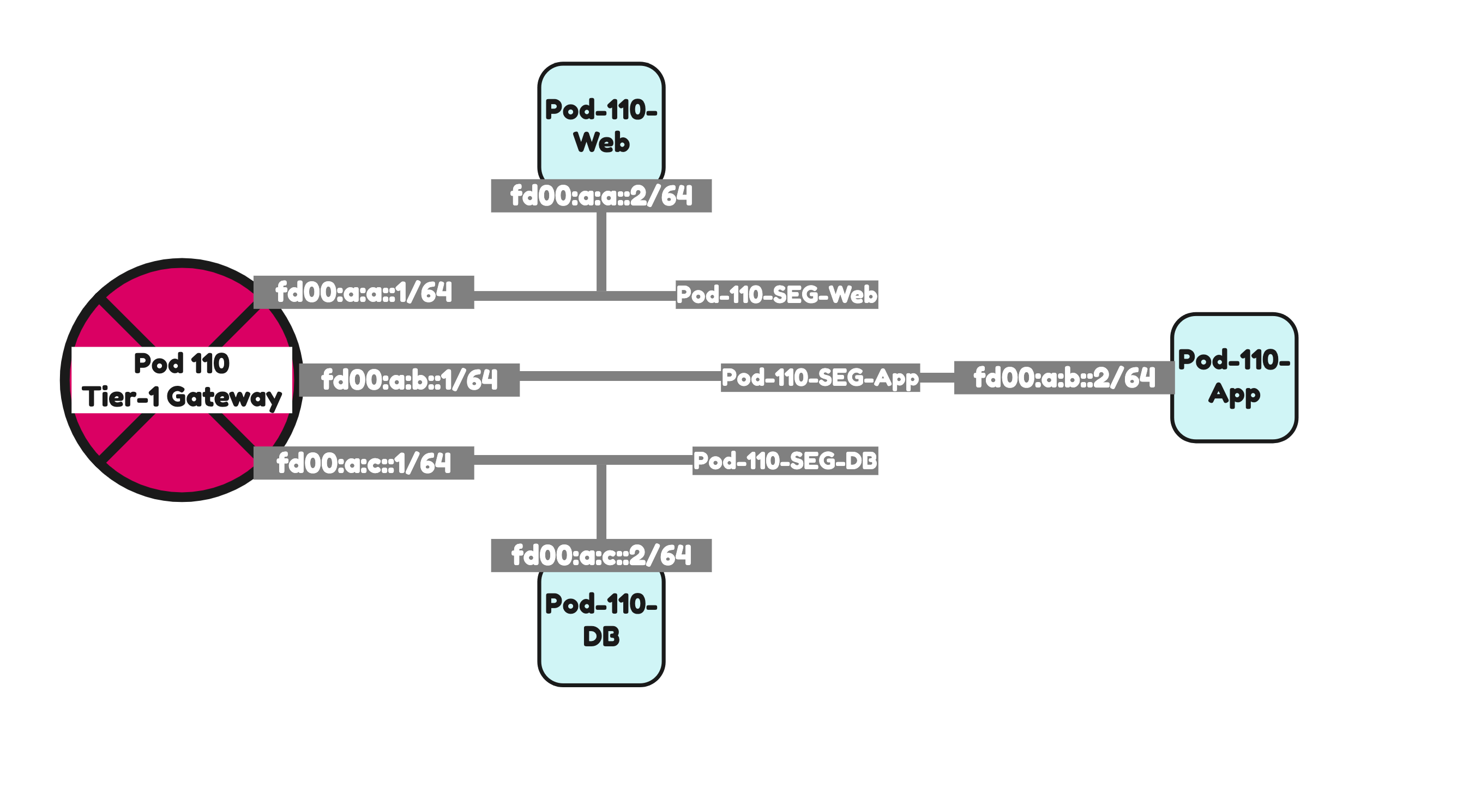
I have created three Virtual Machines, one on each segment using the configuration parameters in the table below.
| VM Name | IPv4 address | IPv4 gateway | IPv6 address | IPv6 gateway |
|---|---|---|---|---|
| Pod-110-Web | 192.168.1.2/24 | 192.168.1.1 | fd00:a:a::2/64 | fd00:a:a::1/64 |
| Pod-110-App | 192.168.2.2/24 | 192.168.2.1 | fd00:a:b::2/64 | fd00:a:b::1/64 |
| Pod-110-DB | 192.168.3.2/24 | 192.168.3.1 | fd00:a:c::3/64 | fd00:a:c::1/64 |
Pod 120
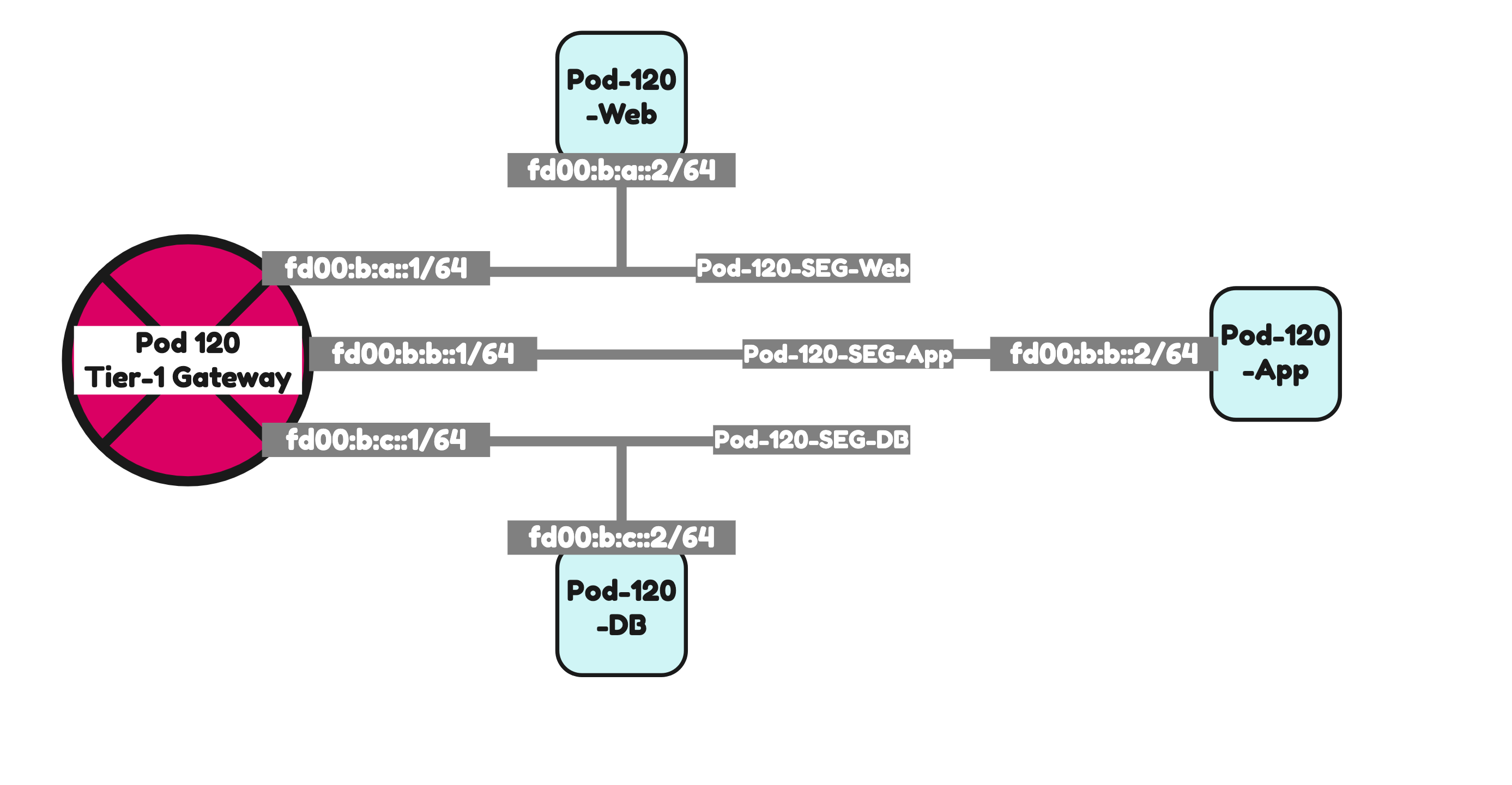
I have created three Virtual Machines, one on each segment using the configuration parameters in the table below.
| VM Name | IPv4 address | IPv4 gateway | IPv6 address | IPv6 gateway |
|---|---|---|---|---|
| Pod-120-Web | 192.168.5.2/24 | 192.168.5.1 | fd00:b:a::2/64 | fd00:b:a::1/64 |
| Pod-120-App | 192.168.6.2/24 | 192.168.6.1 | fd00:b:b::2/64 | fd00:b:b::1/64 |
| Pod-120-DB | 192.168.7.2/24 | 192.168.7.1 | fd00:b:c::3/64 | fd00:b:c::1/64 |
Testing connectivity 1 〈CLI ping〉
Below I have collected all the ping outputs to I can prove that full end-to-end IPv6 connectivity is possible.
Pod 110 to Pod 120 IPv6 connectivity ping tests
tc@TinyVM:~$ ifconfig
eth0      Link encap:Ethernet  HWaddr 00:50:56:9E:5F:CE
          inet addr:192.168.1.240  Bcast:192.168.1.255  Mask:255.255.255.0
          inet6 addr: fd00:a:a:0:250:56ff:fe9e:5fce/64 Scope:Global
          inet6 addr: fd00:a:a::2/64 Scope:Global
          inet6 addr: fe80::250:56ff:fe9e:5fce/64 Scope:Link
          UP BROADCAST RUNNING MULTICAST  MTU:1500  Metric:1
          RX packets:636 errors:0 dropped:0 overruns:0 frame:0
          TX packets:549 errors:0 dropped:0 overruns:0 carrier:0
          collisions:0 txqueuelen:1000
          RX bytes:57952 (56.5 KiB)  TX bytes:116362 (113.6 KiB)

lo        Link encap:Local Loopback
          inet addr:127.0.0.1  Mask:255.0.0.0
          inet6 addr: ::1/128 Scope:Host
          UP LOOPBACK RUNNING  MTU:65536  Metric:1
          RX packets:30 errors:0 dropped:0 overruns:0 frame:0
          TX packets:30 errors:0 dropped:0 overruns:0 carrier:0
          collisions:0 txqueuelen:1000
          RX bytes:19496 (19.0 KiB)  TX bytes:19496 (19.0 KiB)

tc@TinyVM:~$ ping -c 4 fd00:b:a::2
PING fd00:b:a::2 (fd00:b:a::2): 56 data bytes
64 bytes from fd00:b:a::2: seq=0 ttl=58 time=31.348 ms
64 bytes from fd00:b:a::2: seq=1 ttl=58 time=4.846 ms
64 bytes from fd00:b:a::2: seq=2 ttl=58 time=4.887 ms
64 bytes from fd00:b:a::2: seq=3 ttl=58 time=3.872 ms

--- fd00:b:a::2 ping statistics ---
4 packets transmitted, 4 packets received, 0% packet loss
round-trip min/avg/max = 3.872/11.238/31.348 ms
tc@TinyVM:~$ ping -c 4 fd00:b:b::2
PING fd00:b:b::2 (fd00:b:b::2): 56 data bytes
64 bytes from fd00:b:b::2: seq=0 ttl=58 time=9.647 ms
64 bytes from fd00:b:b::2: seq=1 ttl=58 time=3.568 ms
64 bytes from fd00:b:b::2: seq=2 ttl=58 time=3.758 ms
64 bytes from fd00:b:b::2: seq=3 ttl=58 time=3.196 ms

--- fd00:b:b::2 ping statistics ---
4 packets transmitted, 4 packets received, 0% packet loss
round-trip min/avg/max = 3.196/5.042/9.647 ms
tc@TinyVM:~$ ping -c 4 fd00:b:c::2
PING fd00:b:c::2 (fd00:b:c::2): 56 data bytes
64 bytes from fd00:b:c::2: seq=0 ttl=58 time=9.784 ms
64 bytes from fd00:b:c::2: seq=1 ttl=58 time=2.878 ms
64 bytes from fd00:b:c::2: seq=2 ttl=58 time=3.095 ms
64 bytes from fd00:b:c::2: seq=3 ttl=58 time=5.012 ms

--- fd00:b:c::2 ping statistics ---
4 packets transmitted, 4 packets received, 0% packet loss
round-trip min/avg/max = 2.878/5.192/9.784 ms
tc@TinyVM:~$tc@TinyVM:~$ ifconfig
eth0 Link encap:Ethernet HWaddr 00:50:56:9E:31:18
inet addr:192.168.2.240 Bcast:192.168.2.255 Mask:255.255.255.0
inet6 addr: fd00:a:b::2/64 Scope:Global
inet6 addr: fe80::250:56ff:fe9e:3118/64 Scope:Link
inet6 addr: fd00:a:b:0:250:56ff:fe9e:3118/64 Scope:Global
UP BROADCAST RUNNING MULTICAST MTU:1500 Metric:1
RX packets:136 errors:0 dropped:0 overruns:0 frame:0
TX packets:129 errors:0 dropped:0 overruns:0 carrier:0
collisions:0 txqueuelen:1000
RX bytes:16441 (16.0 KiB) TX bytes:47577 (46.4 KiB)
lo Link encap:Local Loopback
inet addr:127.0.0.1 Mask:255.0.0.0
inet6 addr: ::1/128 Scope:Host
UP LOOPBACK RUNNING MTU:65536 Metric:1
RX packets:20 errors:0 dropped:0 overruns:0 frame:0
TX packets:20 errors:0 dropped:0 overruns:0 carrier:0
collisions:0 txqueuelen:1000
RX bytes:12928 (12.6 KiB) TX bytes:12928 (12.6 KiB)
tc@TinyVM:~$ ping -c 4 fd00:b:a::2
PING fd00:b:a::2 (fd00:b:a::2): 56 data bytes
64 bytes from fd00:b:a::2: seq=0 ttl=58 time=16.372 ms
64 bytes from fd00:b:a::2: seq=1 ttl=58 time=4.004 ms
64 bytes from fd00:b:a::2: seq=2 ttl=58 time=4.863 ms
64 bytes from fd00:b:a::2: seq=3 ttl=58 time=4.738 ms
--- fd00:b:a::2 ping statistics ---
4 packets transmitted, 4 packets received, 0% packet loss
round-trip min/avg/max = 4.004/7.494/16.372 ms
tc@TinyVM:~$ ping -c 4 fd00:b:b::2
PING fd00:b:b::2 (fd00:b:b::2): 56 data bytes
64 bytes from fd00:b:b::2: seq=0 ttl=58 time=14.835 ms
64 bytes from fd00:b:b::2: seq=1 ttl=58 time=5.930 ms
64 bytes from fd00:b:b::2: seq=2 ttl=58 time=4.026 ms
64 bytes from fd00:b:b::2: seq=3 ttl=58 time=3.303 ms
--- fd00:b:b::2 ping statistics ---
4 packets transmitted, 4 packets received, 0% packet loss
round-trip min/avg/max = 3.303/7.023/14.835 ms
tc@TinyVM:~$ ping -c 4 fd00:b:c::2
PING fd00:b:c::2 (fd00:b:c::2): 56 data bytes
64 bytes from fd00:b:c::2: seq=0 ttl=58 time=3.017 ms
64 bytes from fd00:b:c::2: seq=1 ttl=58 time=3.283 ms
64 bytes from fd00:b:c::2: seq=2 ttl=58 time=3.823 ms
64 bytes from fd00:b:c::2: seq=3 ttl=58 time=5.541 ms
--- fd00:b:c::2 ping statistics ---
4 packets transmitted, 4 packets received, 0% packet loss
round-trip min/avg/max = 3.017/3.916/5.541 ms
tc@TinyVM:~$tc@TinyVM:~$ ifconfig
eth0 Link encap:Ethernet HWaddr 00:50:56:9E:AC:7D
inet addr:192.168.3.240 Bcast:192.168.3.255 Mask:255.255.255.0
inet6 addr: fd00:a:c::2/64 Scope:Global
inet6 addr: fe80::250:56ff:fe9e:ac7d/64 Scope:Link
inet6 addr: fd00:a:c:0:250:56ff:fe9e:ac7d/64 Scope:Global
UP BROADCAST RUNNING MULTICAST MTU:1500 Metric:1
RX packets:137 errors:0 dropped:0 overruns:0 frame:0
TX packets:119 errors:0 dropped:0 overruns:0 carrier:0
collisions:0 txqueuelen:1000
RX bytes:16152 (15.7 KiB) TX bytes:41590 (40.6 KiB)
lo Link encap:Local Loopback
inet addr:127.0.0.1 Mask:255.0.0.0
inet6 addr: ::1/128 Scope:Host
UP LOOPBACK RUNNING MTU:65536 Metric:1
RX packets:10 errors:0 dropped:0 overruns:0 frame:0
TX packets:10 errors:0 dropped:0 overruns:0 carrier:0
collisions:0 txqueuelen:1000
RX bytes:6464 (6.3 KiB) TX bytes:6464 (6.3 KiB)
tc@TinyVM:~$ ping -c 4 fd00:b:a::2
PING fd00:b:a::2 (fd00:b:a::2): 56 data bytes
64 bytes from fd00:b:a::2: seq=0 ttl=58 time=13.181 ms
64 bytes from fd00:b:a::2: seq=1 ttl=58 time=5.612 ms
64 bytes from fd00:b:a::2: seq=2 ttl=58 time=4.381 ms
64 bytes from fd00:b:a::2: seq=3 ttl=58 time=3.248 ms
--- fd00:b:a::2 ping statistics ---
4 packets transmitted, 4 packets received, 0% packet loss
round-trip min/avg/max = 3.248/6.605/13.181 ms
tc@TinyVM:~$ ping -c 4 fd00:b:b::2
PING fd00:b:b::2 (fd00:b:b::2): 56 data bytes
64 bytes from fd00:b:b::2: seq=0 ttl=58 time=16.429 ms
64 bytes from fd00:b:b::2: seq=1 ttl=58 time=3.889 ms
64 bytes from fd00:b:b::2: seq=2 ttl=58 time=4.668 ms
64 bytes from fd00:b:b::2: seq=3 ttl=58 time=3.704 ms
--- fd00:b:b::2 ping statistics ---
4 packets transmitted, 4 packets received, 0% packet loss
round-trip min/avg/max = 3.704/7.172/16.429 ms
tc@TinyVM:~$ ping -c 4 fd00:b:c::2
PING fd00:b:c::2 (fd00:b:c::2): 56 data bytes
64 bytes from fd00:b:c::2: seq=0 ttl=58 time=5.868 ms
64 bytes from fd00:b:c::2: seq=1 ttl=58 time=3.302 ms
64 bytes from fd00:b:c::2: seq=2 ttl=58 time=4.182 ms
64 bytes from fd00:b:c::2: seq=3 ttl=58 time=3.468 ms
--- fd00:b:c::2 ping statistics ---
4 packets transmitted, 4 packets received, 0% packet loss
round-trip min/avg/max = 3.302/4.205/5.868 ms
tc@TinyVM:~$
Pod 120 to Pod 110 IPv6 connectivity ping tests
tc@TinyVM:~$ ifconfig
eth0      Link encap:Ethernet  HWaddr 00:50:56:85:66:7D
          inet addr:192.168.5.240  Bcast:192.168.5.255  Mask:255.255.255.0
          inet6 addr: fd00:b:a::2/64 Scope:Global
          inet6 addr: fe80::250:56ff:fe85:667d/64 Scope:Link
          inet6 addr: fd00:b:a:0:250:56ff:fe85:667d/64 Scope:Global
          UP BROADCAST RUNNING MULTICAST  MTU:1500  Metric:1
          RX packets:206 errors:0 dropped:0 overruns:0 frame:0
          TX packets:159 errors:0 dropped:0 overruns:0 carrier:0
          collisions:0 txqueuelen:1000
          RX bytes:21572 (21.0 KiB)  TX bytes:46940 (45.8 KiB)

lo        Link encap:Local Loopback
          inet addr:127.0.0.1  Mask:255.0.0.0
          inet6 addr: ::1/128 Scope:Host
          UP LOOPBACK RUNNING  MTU:65536  Metric:1
          RX packets:10 errors:0 dropped:0 overruns:0 frame:0
          TX packets:10 errors:0 dropped:0 overruns:0 carrier:0
          collisions:0 txqueuelen:1000
          RX bytes:6464 (6.3 KiB)  TX bytes:6464 (6.3 KiB)

tc@TinyVM:~$ ping -c 4 fd00:a:a::2
PING fd00:a:a::2 (fd00:a:a::2): 56 data bytes
64 bytes from fd00:a:a::2: seq=0 ttl=58 time=3.856 ms
64 bytes from fd00:a:a::2: seq=1 ttl=58 time=3.572 ms
64 bytes from fd00:a:a::2: seq=2 ttl=58 time=3.405 ms
64 bytes from fd00:a:a::2: seq=3 ttl=58 time=3.204 ms

--- fd00:a:a::2 ping statistics ---
4 packets transmitted, 4 packets received, 0% packet loss
round-trip min/avg/max = 3.204/3.509/3.856 ms
tc@TinyVM:~$ ping -c 4 fd00:a:b::2
PING fd00:a:b::2 (fd00:a:b::2): 56 data bytes
64 bytes from fd00:a:b::2: seq=0 ttl=58 time=23.314 ms
64 bytes from fd00:a:b::2: seq=1 ttl=58 time=6.001 ms
64 bytes from fd00:a:b::2: seq=2 ttl=58 time=4.059 ms
64 bytes from fd00:a:b::2: seq=3 ttl=58 time=5.081 ms

--- fd00:a:b::2 ping statistics ---
4 packets transmitted, 4 packets received, 0% packet loss
round-trip min/avg/max = 4.059/9.613/23.314 ms
tc@TinyVM:~$ ping -c 4 fd00:a:c::2
PING fd00:a:c::2 (fd00:a:c::2): 56 data bytes
64 bytes from fd00:a:c::2: seq=0 ttl=58 time=10.396 ms
64 bytes from fd00:a:c::2: seq=1 ttl=58 time=2.275 ms
64 bytes from fd00:a:c::2: seq=2 ttl=58 time=3.289 ms
64 bytes from fd00:a:c::2: seq=3 ttl=58 time=3.030 ms

--- fd00:a:c::2 ping statistics ---
4 packets transmitted, 4 packets received, 0% packet loss
round-trip min/avg/max = 2.275/4.747/10.396 ms
tc@TinyVM:~$tc@TinyVM:~$ ifconfig
eth0 Link encap:Ethernet HWaddr 00:50:56:85:40:F8
inet addr:192.168.6.240 Bcast:192.168.6.255 Mask:255.255.255.0
inet6 addr: fd00:b:b:0:250:56ff:fe85:40f8/64 Scope:Global
inet6 addr: fd00:b:b::2/64 Scope:Global
inet6 addr: fe80::250:56ff:fe85:40f8/64 Scope:Link
UP BROADCAST RUNNING MULTICAST MTU:1500 Metric:1
RX packets:170 errors:0 dropped:0 overruns:0 frame:0
TX packets:145 errors:0 dropped:0 overruns:0 carrier:0
collisions:0 txqueuelen:1000
RX bytes:20497 (20.0 KiB) TX bytes:70044 (68.4 KiB)
lo Link encap:Local Loopback
inet addr:127.0.0.1 Mask:255.0.0.0
inet6 addr: ::1/128 Scope:Host
UP LOOPBACK RUNNING MTU:65536 Metric:1
RX packets:20 errors:0 dropped:0 overruns:0 frame:0
TX packets:20 errors:0 dropped:0 overruns:0 carrier:0
collisions:0 txqueuelen:1000
RX bytes:13000 (12.6 KiB) TX bytes:13000 (12.6 KiB)
tc@TinyVM:~$ ping -c 4 fd00:a:a::2
PING fd00:a:a::2 (fd00:a:a::2): 56 data bytes
64 bytes from fd00:a:a::2: seq=0 ttl=58 time=10.618 ms
64 bytes from fd00:a:a::2: seq=1 ttl=58 time=4.168 ms
64 bytes from fd00:a:a::2: seq=2 ttl=58 time=3.763 ms
64 bytes from fd00:a:a::2: seq=3 ttl=58 time=3.500 ms
--- fd00:a:a::2 ping statistics ---
4 packets transmitted, 4 packets received, 0% packet loss
round-trip min/avg/max = 3.500/5.512/10.618 ms
tc@TinyVM:~$ ping -c 4 fd00:a:b::2
PING fd00:a:b::2 (fd00:a:b::2): 56 data bytes
64 bytes from fd00:a:b::2: seq=0 ttl=58 time=7.505 ms
64 bytes from fd00:a:b::2: seq=1 ttl=58 time=3.095 ms
64 bytes from fd00:a:b::2: seq=2 ttl=58 time=3.237 ms
64 bytes from fd00:a:b::2: seq=3 ttl=58 time=3.434 ms
--- fd00:a:b::2 ping statistics ---
4 packets transmitted, 4 packets received, 0% packet loss
round-trip min/avg/max = 3.095/4.317/7.505 ms
tc@TinyVM:~$ ping -c 4 fd00:a:c::2
PING fd00:a:c::2 (fd00:a:c::2): 56 data bytes
64 bytes from fd00:a:c::2: seq=0 ttl=58 time=11.369 ms
64 bytes from fd00:a:c::2: seq=1 ttl=58 time=2.987 ms
64 bytes from fd00:a:c::2: seq=2 ttl=58 time=10.894 ms
64 bytes from fd00:a:c::2: seq=3 ttl=58 time=4.446 ms
--- fd00:a:c::2 ping statistics ---
4 packets transmitted, 4 packets received, 0% packet loss
round-trip min/avg/max = 2.987/7.424/11.369 ms
tc@TinyVM:~$tc@TinyVM:~$ ifconfig
eth0 Link encap:Ethernet HWaddr 00:50:56:85:78:4B
inet addr:192.168.7.240 Bcast:192.168.7.255 Mask:255.255.255.0
inet6 addr: fd00:b:c::2/64 Scope:Global
inet6 addr: fd00:b:c:0:250:56ff:fe85:784b/64 Scope:Global
inet6 addr: fe80::250:56ff:fe85:784b/64 Scope:Link
UP BROADCAST RUNNING MULTICAST MTU:1500 Metric:1
RX packets:178 errors:0 dropped:0 overruns:0 frame:0
TX packets:166 errors:0 dropped:0 overruns:0 carrier:0
collisions:0 txqueuelen:1000
RX bytes:20023 (19.5 KiB) TX bytes:51135 (49.9 KiB)
lo Link encap:Local Loopback
inet addr:127.0.0.1 Mask:255.0.0.0
inet6 addr: ::1/128 Scope:Host
UP LOOPBACK RUNNING MTU:65536 Metric:1
RX packets:34 errors:0 dropped:0 overruns:0 frame:0
TX packets:34 errors:0 dropped:0 overruns:0 carrier:0
collisions:0 txqueuelen:1000
RX bytes:13731 (13.4 KiB) TX bytes:13731 (13.4 KiB)
tc@TinyVM:~$ ping -c 4 fd00:a:a::2
PING fd00:a:a::2 (fd00:a:a::2): 56 data bytes
64 bytes from fd00:a:a::2: seq=0 ttl=58 time=3.223 ms
64 bytes from fd00:a:a::2: seq=1 ttl=58 time=3.522 ms
64 bytes from fd00:a:a::2: seq=2 ttl=58 time=3.361 ms
64 bytes from fd00:a:a::2: seq=3 ttl=58 time=3.831 ms
--- fd00:a:a::2 ping statistics ---
4 packets transmitted, 4 packets received, 0% packet loss
round-trip min/avg/max = 3.223/3.484/3.831 ms
tc@TinyVM:~$ ping -c 4 fd00:a:b::2
PING fd00:a:b::2 (fd00:a:b::2): 56 data bytes
64 bytes from fd00:a:b::2: seq=0 ttl=58 time=10.482 ms
64 bytes from fd00:a:b::2: seq=1 ttl=58 time=2.637 ms
64 bytes from fd00:a:b::2: seq=2 ttl=58 time=2.015 ms
64 bytes from fd00:a:b::2: seq=3 ttl=58 time=4.101 ms
--- fd00:a:b::2 ping statistics ---
4 packets transmitted, 4 packets received, 0% packet loss
round-trip min/avg/max = 2.015/4.808/10.482 ms
tc@TinyVM:~$ ping -c 4 fd00:a:c::2
PING fd00:a:c::2 (fd00:a:c::2): 56 data bytes
64 bytes from fd00:a:c::2: seq=0 ttl=58 time=8.601 ms
64 bytes from fd00:a:c::2: seq=1 ttl=58 time=2.742 ms
64 bytes from fd00:a:c::2: seq=2 ttl=58 time=2.583 ms
64 bytes from fd00:a:c::2: seq=3 ttl=58 time=2.850 ms
--- fd00:a:c::2 ping statistics ---
4 packets transmitted, 4 packets received, 0% packet loss
round-trip min/avg/max = 2.583/4.194/8.601 ms
tc@TinyVM:~$
Testing connectivity 2 〈Traceflow〉
As an extra test I also did some traceflow tests,
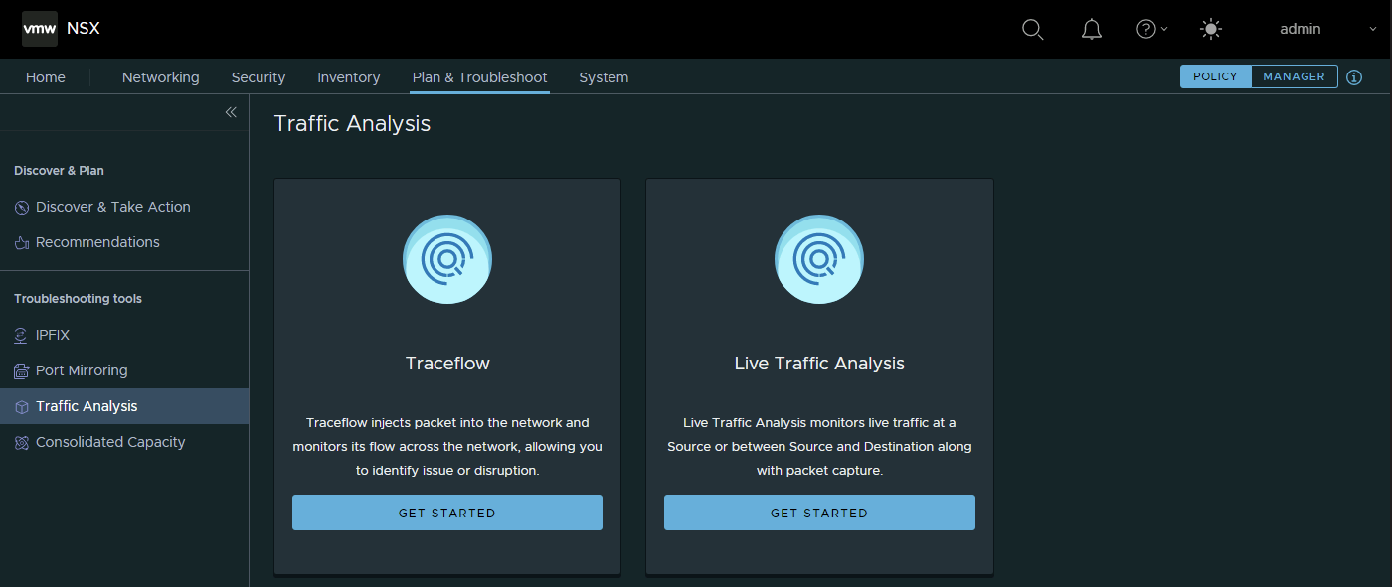
Pod 110 Web to Pod 120 Web IPv6 traceflow test
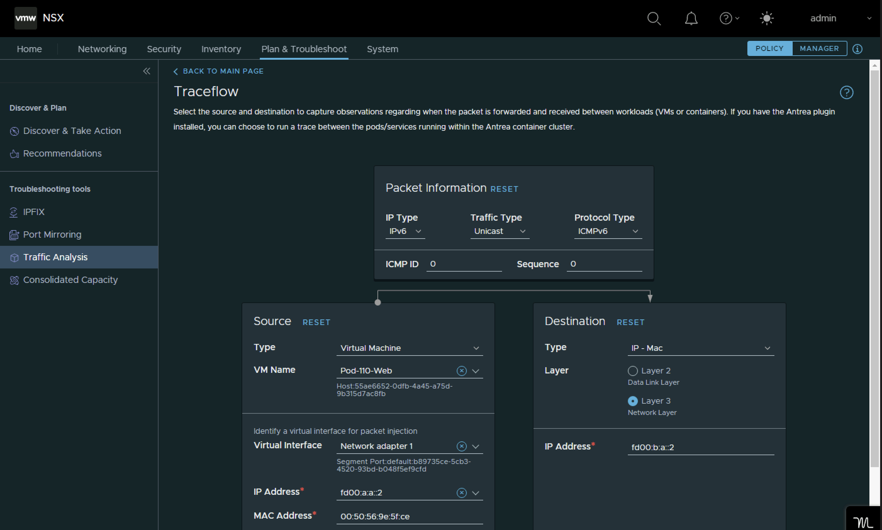
The packets are successfully delivered.
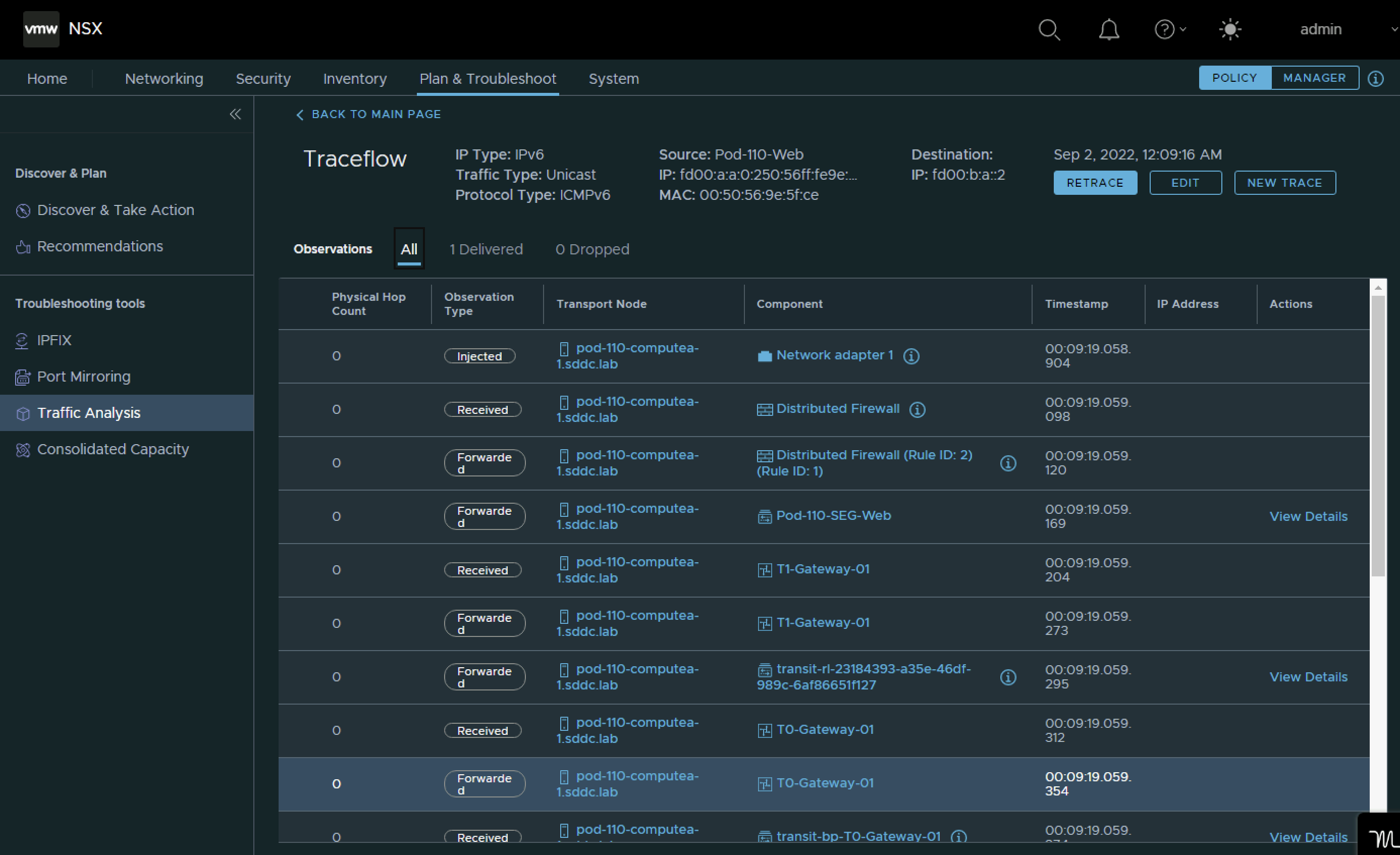
Pod 110 Web to Pod 110 App IPv6 traceflow test
Because the traffic is now staying within the same NSX Domain (Web to App inside Pod 110) traceflow generates a nice diagram and shows how the traffic is flowing. The packets are successfully delivered.