Deploying your first VNF with TCA
I have shown you how to set up the complete infra with TCA and VCD here.
In this article, I will show you how to deploy your first VNF.
Configuration Steps
There are two ways to upload the application VMs.
- Using vCenter Server
- Import the OVA's in vCenter Server, not power them on and convert them to a Template
- Using VCD
- Import the files into a catalog
I am going to show you both ways.
- STEP 1: Upload OVA Virtual Machines using vCenter Server (Templates)
- STEP 2: Upload OVA Virtual Machines using VCD Catalogs
- STEP 3: Upload the TOSCA template to TCA
- STEP 4: Instantiate the VNF (using the vSphere Templates)
- STEP 5: Instantiate your first VNF (using the VCD Catalog)
The application that I am onboarding will consist out of three Virtual Machines:
- centos-small-lb
- centos-small-app
- centos-small-db
I will upload/deploy copies of the same VM in vSphere and VCD, and even though you only need them in one place I will show you how to deploy them from both places.
STEP 1» Upload OVA Virtual Machines using vCenter Server 〈Templates〉
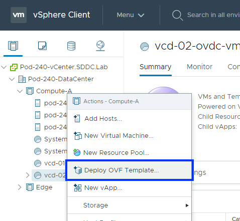
I have deployed each OVA (lb, app and db) using vCenter Server:
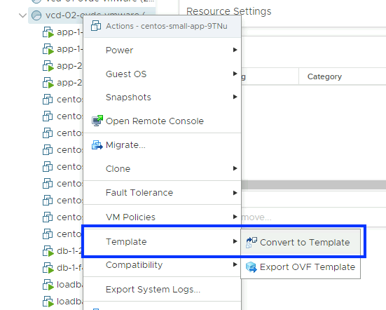
When the deployment was done I have converted the VM's to a Template:
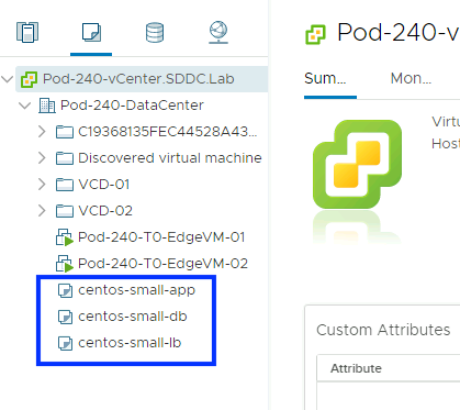
This resulted that all three Virtual Machines are now Template objects inside the vCenter Server.
STEP 2» Upload OVA Virtual Machines using VCD Catalogs
I have also uploaded the same VMs using the catalog feature inside VCD.
You need to log in as the Organization "administrator" account of the Organization.
Inside the Organization Portal select "Libraries" and create a new "Catalog"
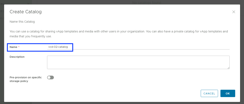
Provide a name for the new "Catalog".
Verify if the "Catalog" is correctly created without any errors.
Click on "vApp Templates" and create a new vApp Template.
Select the OVA you want to upload.
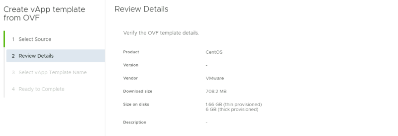
Review the details.
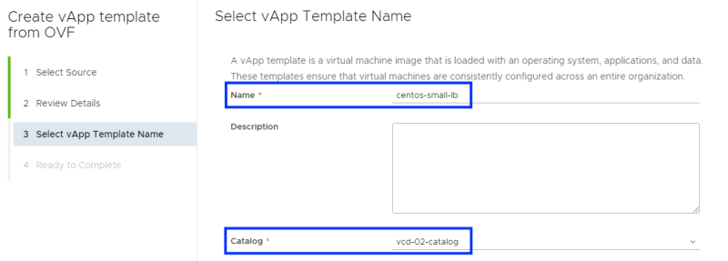
Provide a name for the vApp Template and specify a catalog where you want to place this template in. This is the catalog that I have just created.
Complete the vApp Template configuration.
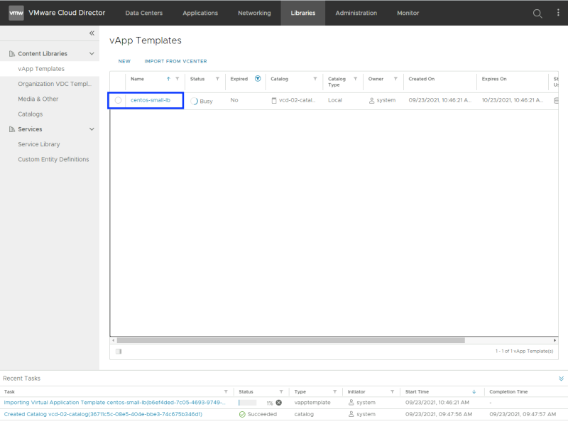
Verify if the vApp Template is correctly created without any errors.
Do the same with the other two remaining OVA Templates, as you have now only created a vApp Template for the "centos-small"lb" VM.
When all vApp Templates are created for all VMs the screen should look like this:
STEP 3» Upload the TOSCA template to TCA
Now that the VM Templates are "in place" you can start uploading the TOSCA template to the TCA Manager.
Onboard a network function
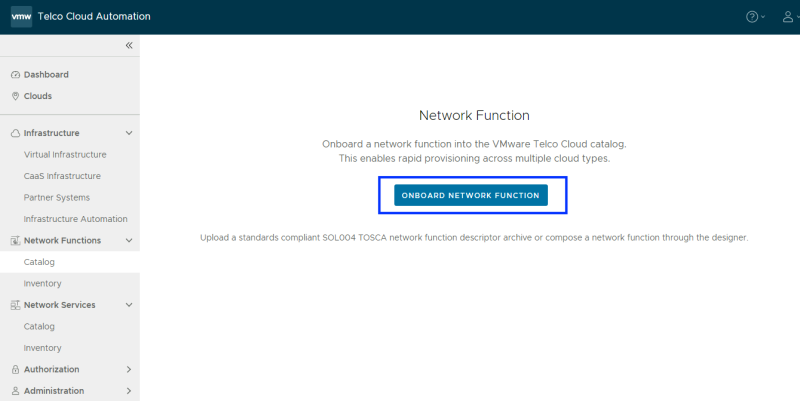
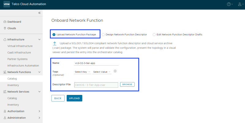
Click on "Catalog" and choose "Onboard Network Function".
Provide a name for the new "Network Function" and select the CSAR file.
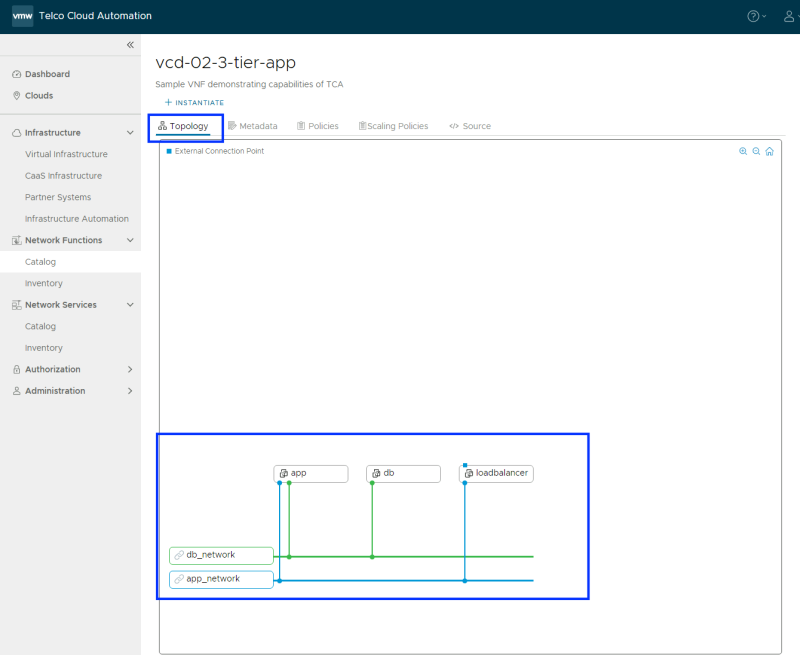
After you have clicked on "upload" a Topology will be presented. Now you are ready to instantiate a VNF based on this Network Function/Topology.
STEP 4» Instantiate the VNF 〈using the vSphere Templates〉
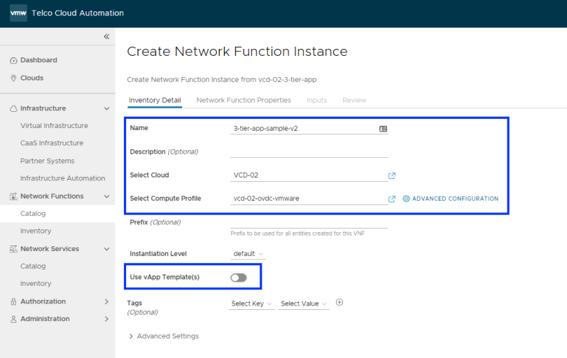
Select the Network Function you want to instantiate a VNF form and click on "instantiate".
Provide a name for the new "VNF" and select a "Cloud" (Organization VDC) and the "Compute Profile".
I have NOT enabled the "Use vApp Template" switch because I want to instantiate from the vSphere Template VMs.
This is how the screen will look like when you need to select a "Cloud".
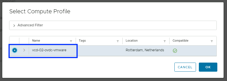
This is how the screen will look like when you need to select a "Compute Profile".
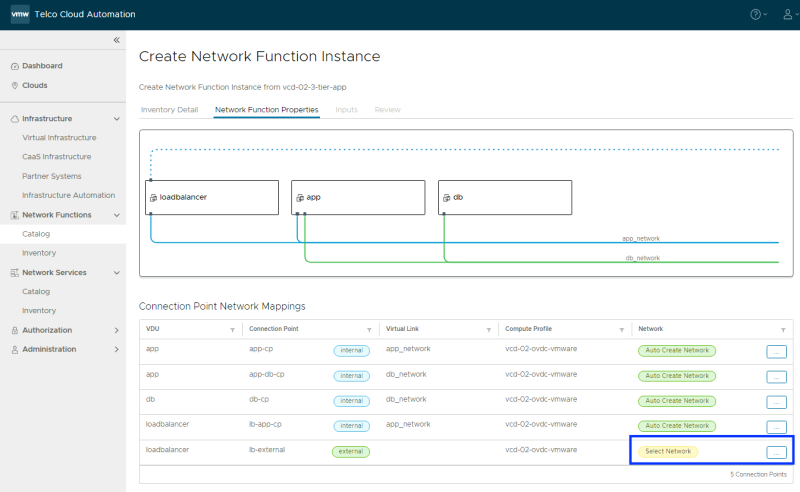
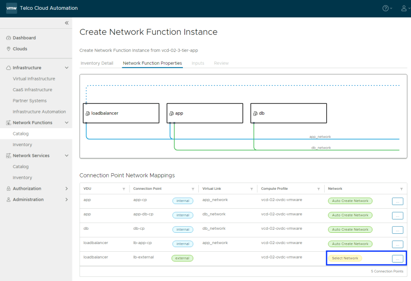
The networks for APP and DB will be created automatically as an "isolated" network. The Loadbalancer VM will need an external connection that you need to specify.
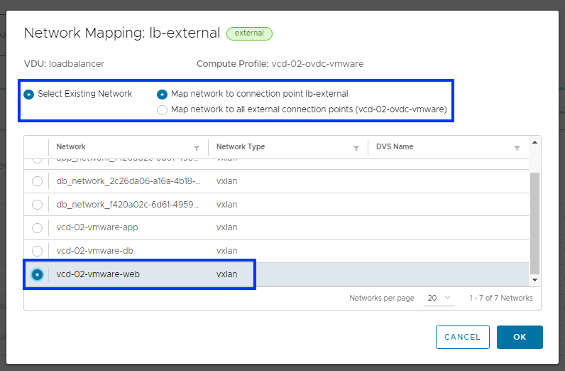
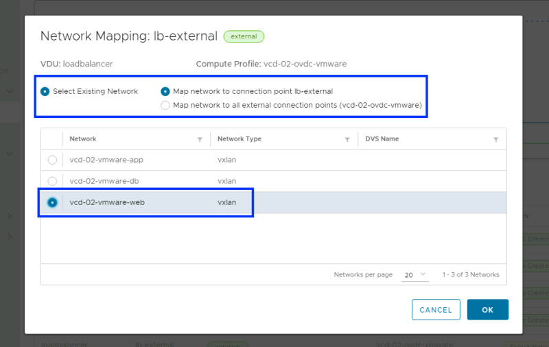
I have created the "vcd-02-vmware-web" network that is mapped to the "Seg-Web"Logical Switch/Segment on NSX-T so I will select this network.
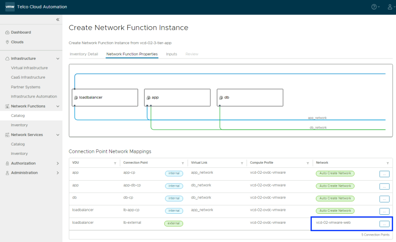
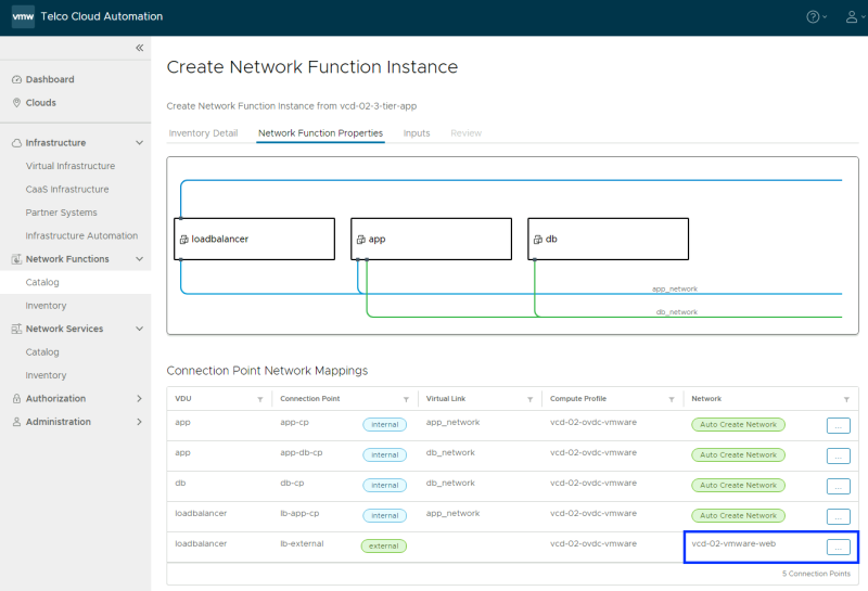
When the external network is selected your screen will look like this:
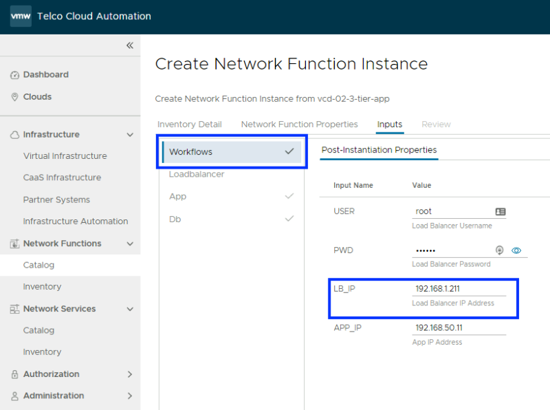
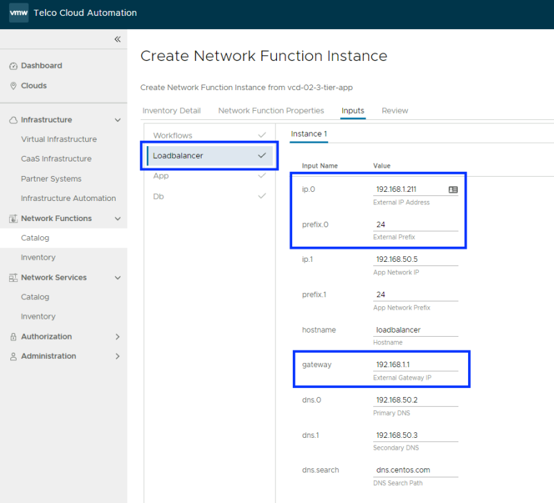
Workflows tab: The external IP address for the Loadbalancer needs to be specified manually. In my example, I will use 192.168.1.211.
Loadbalancer tab: The external IP address for the Loadbalancer needs to be specified manually here as well and the Prefix and the Gateway. All other fields/tabs are populated automatically based on the code in the CSAR.
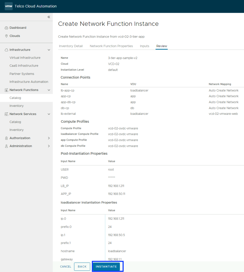
Complete the new VNF instantiation.
Checking the Deployed VNF
Verify if the VNF is correctly instantiated without any errors. The state is "Completed"
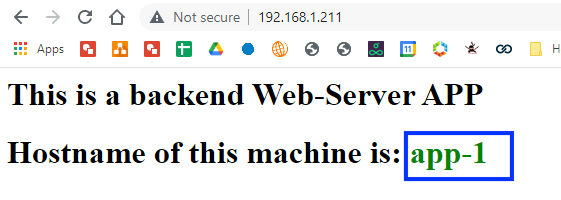
Test the application reachability
Verify if the Application is correctly reachable without any errors using the IP address I have specified (192.168.1.211).
STEP 5» Instantiate your first VNF 〈using the VCD Catalog〉
Select the Network Function you want to instantiate a VNF form and click on "instantiate".
Provide a name for the new "VNF" and select a "Cloud" (Organization VDC) and the "Compute Profile".
this time I HAVE enabled the "Use vApp Template" switch because I want to instantiate from the VCD Catalog, and I have selected the VCD Catalog name as well.
I have NOT enabled the "Use vApp Template" switch because I want to instantiate from the vSphere Template VMs.
I have created the "vcd-02-vmware-web" network that is mapped to the "Seg-Web"Logical Switch/Segment on NSX-T so I will select this network.
When the external network is selected your screen will look like this:
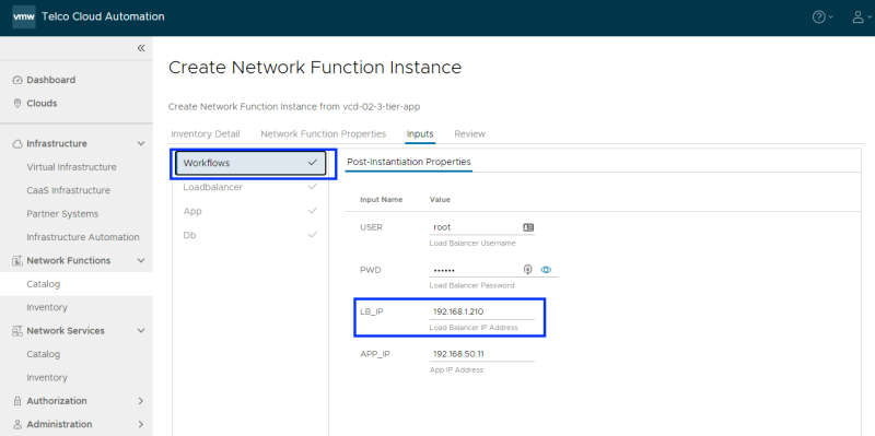
Workflows tab: The external IP address for the Loadbalancer needs to be specified manually. In my example, I will use 192.168.1.210.
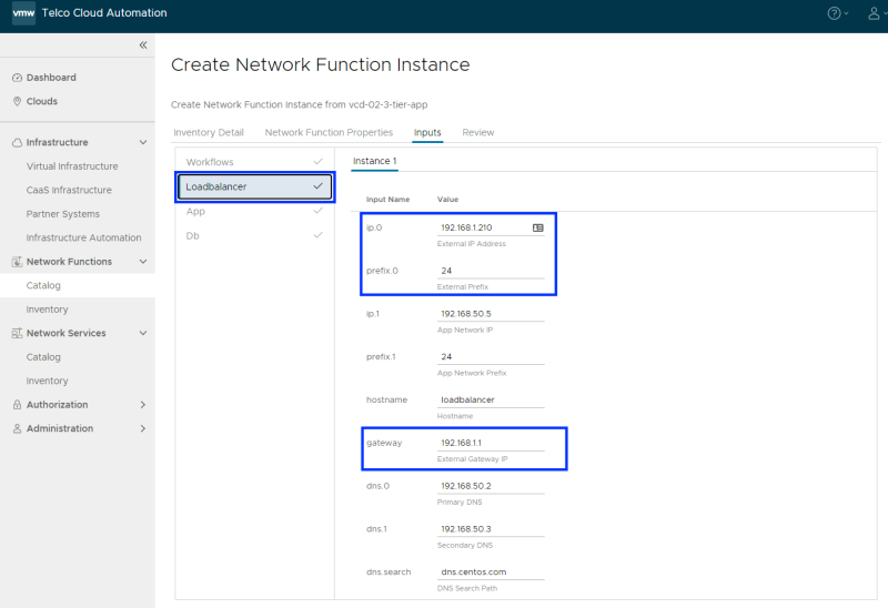
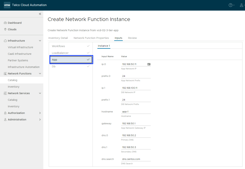
Loadbalancer tab: The external IP address for the Loadbalancer needs to be specified manually here as well and the Prefix and the Gateway. All other fields are populated automatically based on the code in the CSAR.
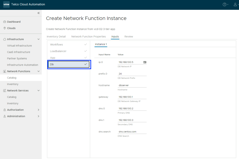
All other fields/tabs are populated automatically based on the code in the CSAR.
All other fields/tabs are populated automatically based on the code in the CSAR.
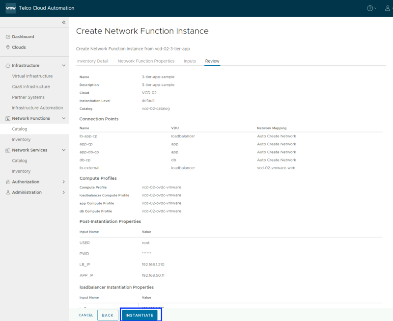
Complete the new VNF instantiation.
Checking the Deployed VNF
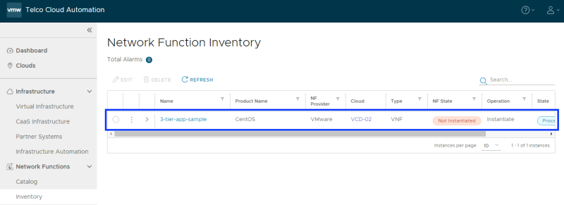
Verify if the VNF is correctly instantiated without any errors. The state is "Processing".
You can follow along and see if new VMs are being created r of already created in the vCenter Server.
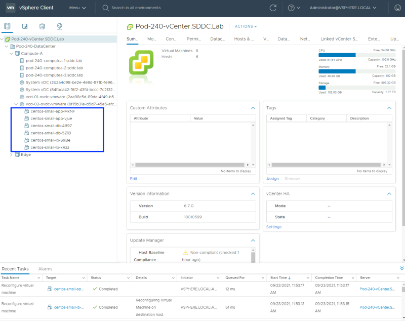
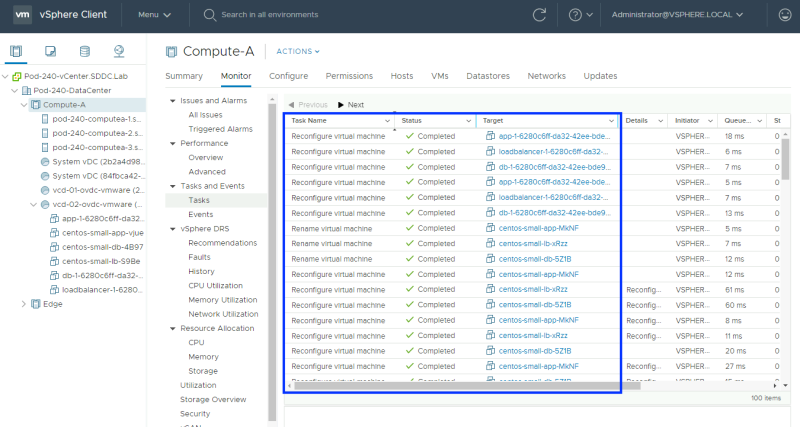
You can look at the tasks in the vCenter Server to verify the (successfully) completed tasks.
You can also follow along in vCloud Director and verify if the app and db isolated networks are created.
You can also follow along in NSX-T Manager and verify if the app and db isolated networks are created.
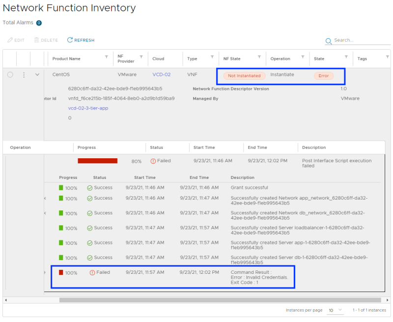
This time you see that the state has ended in "Error"
A closer look at the error shows that there is something wrong with the Credentials.
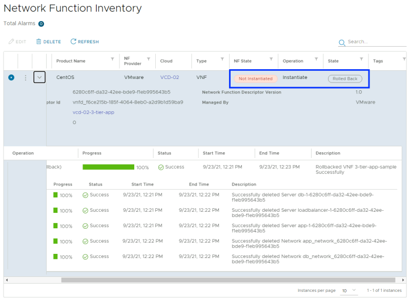
I decided to do a "rollback" of this VNF and delete all the VMs and Networks that were created.
The issue is that VCD "turns on" Guest Customization for the vApp Templates you created and there is no way to turn this off during the creation of the vApp Templates.
What you CAN do is create a VM from the vApp Template and edit the Guest Customization (turn it off) and upload it as a new vApp Template in the Catalog with a new name (or use a new Catalog. This procedure is shown below.
Workaround to make VCD Catalog Items work
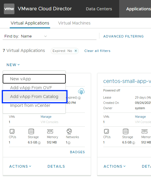
Add a new vApp from Catalog.
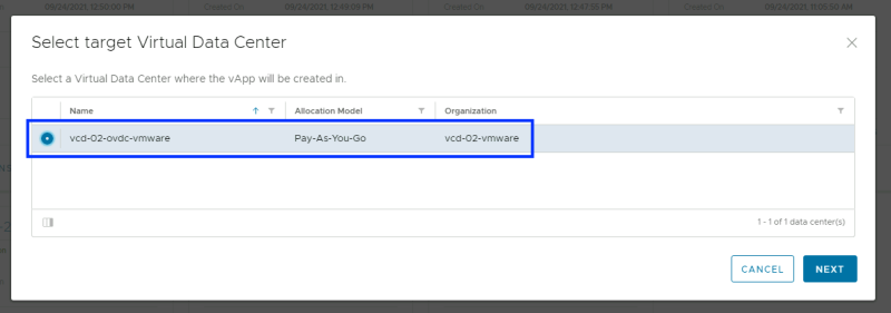
Select the Organization VDC.
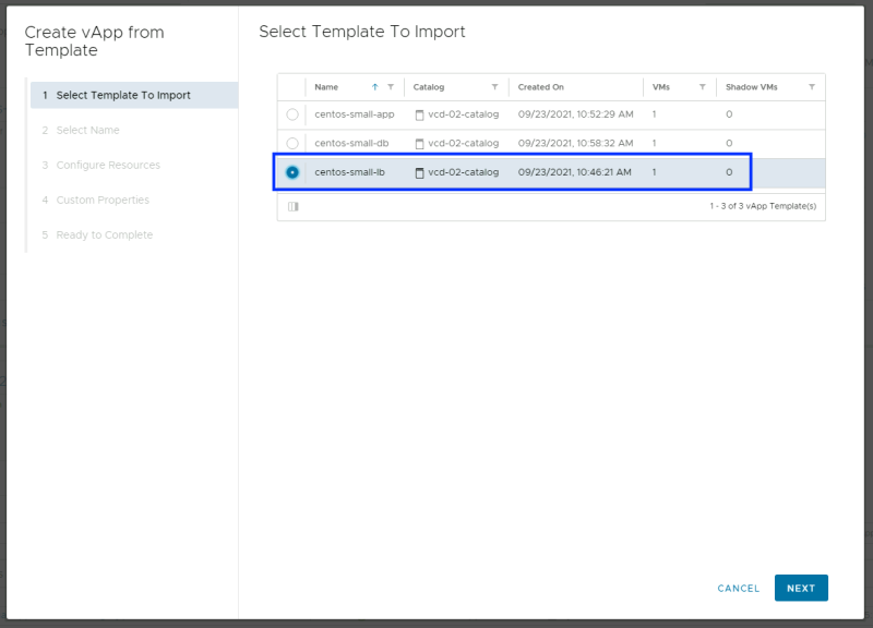
Select the vApp Template that you want to use for the import.
Provide a name.
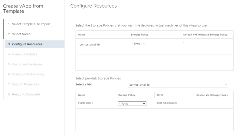
Configure the Resources (leave the defaults in).
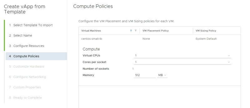
Configure the Compute Policies (leave the defaults in).
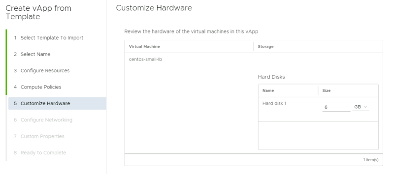
Customize the hardware (leave the defaults in).
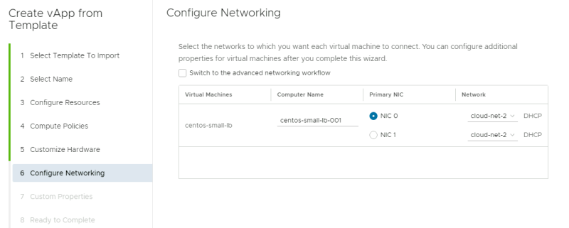
Customize Networking (leave the defaults in).
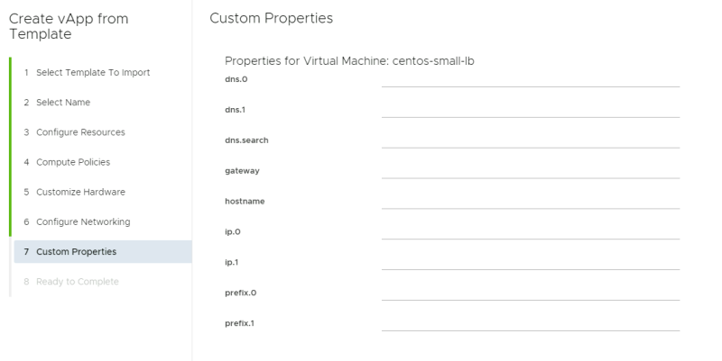
Customize the Properties (leave the defaults in, so leave everything blank)).
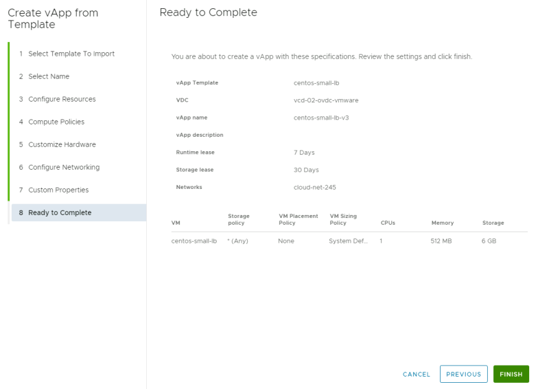
Complete the vApp from Template creation.
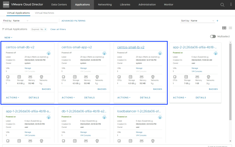
Do the same with the other two remaining vApps, as you have now only created a vApp for the "centos-small"lb" VM. Make sure you DO NOT POWER ON any of the newly created VMs.
When all vApp/VMs are created for all VMs the screen should look like this:
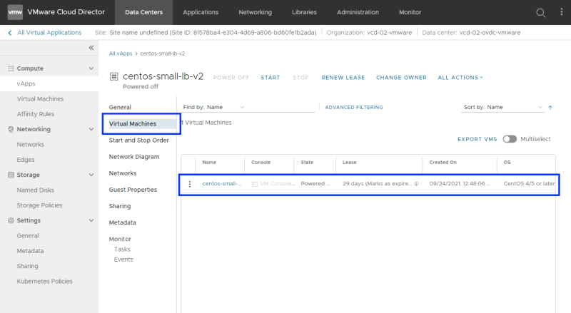
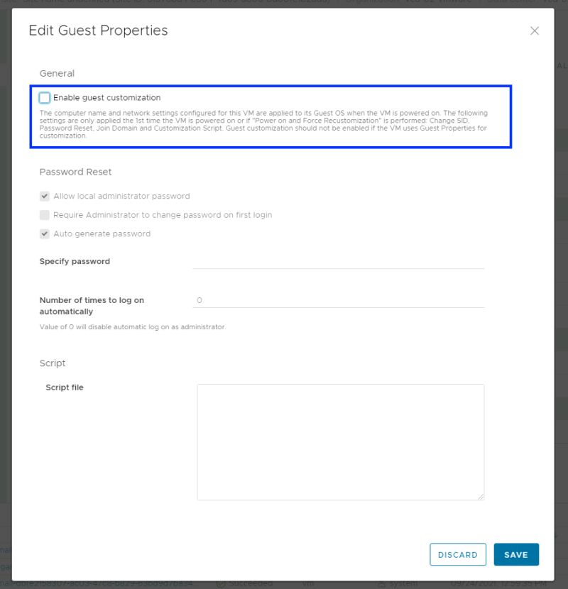
Now you need to go into the vApp and go to the Virtual Machine and click on the VM to DISABLE the Guest Customization.
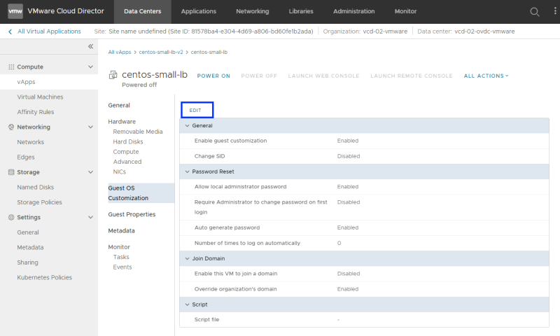
Click on "Edit".
Uncheck the "Enable guest customization" checkbox.
Verify if the Guest customization is disabled now.
Do the same for the other vApps/VMs.
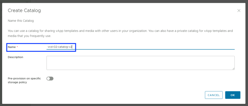
Before I am going to convert the vApps/VMs back into vApp Templates and will first create a new Catalog, as I like to keep things organized and separated.
Provide a name for the new "Catalog".
Verify if the Catalog is correctly created without any errors.
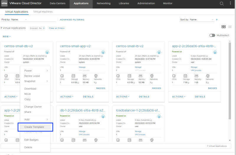
Create a template from the vApp/VM.
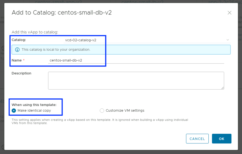
Add the new vApp Template to the new Catalog.
Do the same for all vApps/VMs.
When you look at the Catalog you see that the amount of vApp Templates is now set to "3". So our new Catalog is correctly populated with our new vApp Templates with the Gues Customization Disabled.
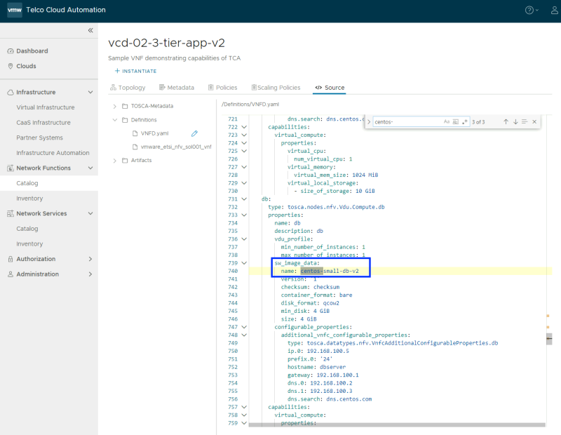
Before you can instantiate a new VNF using the catalog I need to change the code in the CSAR file to point to the new "v2" vApps/VMs that are contained in the new VCD Catalog.
You can edit the existing CSAR, Save it as DRAFT, and save it as a new template with a new name.
Checking the 〈Re〉Deployed VNF
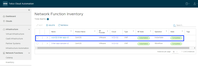
After following the same steps from STEP 5 I have now a new VNF that is in the "Complete" state using the vApp Templates from the new VCD Catalog.
Test the application reachability
This time I have used the external IP address of 192.168.1.212 for the Load Balancer and you can see that the Application is reachable.
In the next article, I will show you how you can scale the VNF by adding a second application VM/Server behind the load balancer.
Summary of deployed VNFs
In the figure below you will see a summary of all the deployed VNFs and what VNF used what Template Sources.
In this next article, I will show you how to scale this VNF using TCA.
