Container apps on Virtual Instance Worker Nodes (inside OKE) with containers SR-IOV enabled network interfaces and the Multus CNI plugin
Introduction
In this tutorial, we will explore how to deploy containerized applications on Virtual Instance Worker Nodes within Oracle Kubernetes Engine (OKE), leveraging advanced networking capabilities. Specifically, we’ll enable SR-IOV (Single Root I/O Virtualization) for container network interfaces and configure the Multus CNI plugin to enable multi-homed networking for your containers.
By combining SR-IOV with Multus, you can achieve high-performance, low-latency networking for specialized workloads such as AI, machine learning, and real-time data processing. This guide will provide step-by-step instructions to configure your OKE environment, deploy worker nodes with SR-IOV-enabled interfaces, and use Multus CNI to manage multiple network interfaces in your pods. Whether you're aiming for high-speed packet processing or need to fine-tune your Kubernetes networking, this tutorial will equip you with the tools and knowledge to get started.
At the time of writing of this article the SR-IOV CNI can not be used by pods/containers on a Virtual Instance that is part of an OCI OKE cluster together with the Multus CNI plugin.
In this article we will show you how you can use an SR-IOV enabled interface inside a pod running on pods/containers on a Virtual Instance that is part of an OCI OKE cluster by MOVING the VNIC (that is on a Virtual Instance) into a POD and is usable with the help of the Multus CNI plugin (where the SR-IOV CNI plugin is not used at all).
The SR-IOV CNI plugin IS supported on a Bare Metal Instance that is part of an OCI OKE cluster together with the Multus CNI plugin. This is out of the scope of this tutorial.
The Steps
- [ ] STEP 01 - Make sure OKE is deployed with a bastion and operator and 3 x VM worker nodes with the Flannel CNI plugin
- [ ] STEP 02 - Enable Hardware-assisted (SR-IOV) networking on each worker node
- [ ] STEP 03 - Create a new subnet for the sriov enabled VNICs
- [ ] STEP 04 - Add a second VNIC Attachment
- [ ] STEP 05 - Assign an IP address to the new second VNIC with a default gateway
- [ ] STEP 06 - Install a Meta-Plugin CNI (Multus) on the worker node
- [ ] STEP 07 - Attach network interfaces to PODs
- [ ] STEP 08 - Do some ping tests between multiple PODs
- [ ] STEP 09 - (OPTIONAL) Deploy PODs with multiple interfaces
- [ ] STEP 10 - Remove all POD deployments
STEP 01 - Make sure OKE is deployed with a bastion and operator and 3 x VM worker nodes and the Flannel CNI plugin
Before proceeding with this tutorial, ensure that Oracle Kubernetes Engine (OKE) is deployed with the following setup:
- Bastion
- Operator
- 3 VM Worker Nodes
- Flannel CNI Plugin
This setup is detailed in the following tutorial: [Deploy a Kubernetes Cluster with Terraform using Oracle Cloud Infrastructure Kubernetes Engine].
Make sure to complete the steps outlined there before starting this guide.
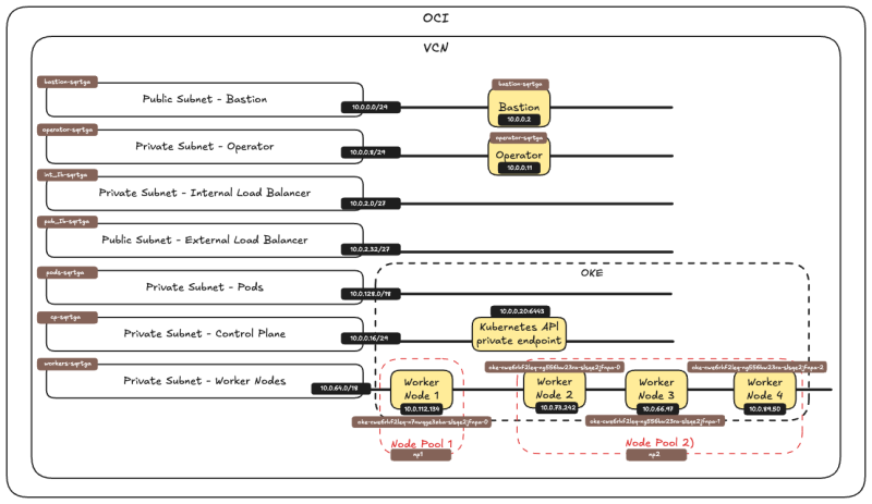
Below is a visual overview of the components we will work with throughout this tutorial.
STEP 02 - Enable Hardware-assisted -SR-IOV- networking on each worker node
The following actions need to be performed on all the Worker Nodes that are part of the OKE cluster.
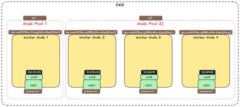
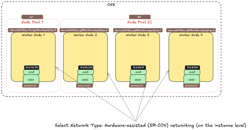
The picture below is a visual overview of our Worker Nodes inside the OKE cluster that we will work with throughout this tutorial.
Enable SR-IOV on the Instance
Log in with SSH to the Instance / Worker Node.
- Use the command
lspcito verify what network driver is currently used on all the VNICs.2 - Notice that the
Virtio SCSInetwork driver is used.
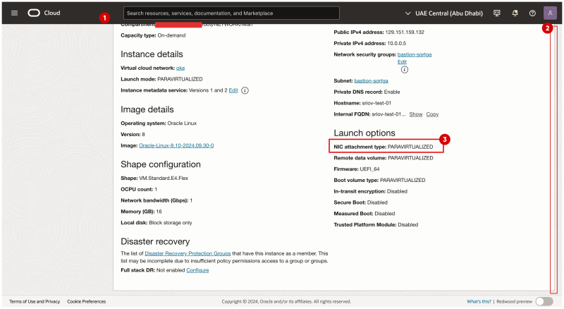
- Browse to the Instance / Worker Node in the OCI Console.
- Scroll down.
- Notice that the NIC attachment type is now PARAVIRTUALIZED.
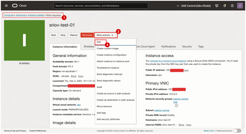
- Browse to the Instance / Worker Node in the OCI Console.
- Click on More Actions.
- Click on Edit.
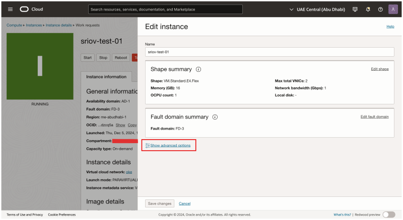
Click on Show advanced options.
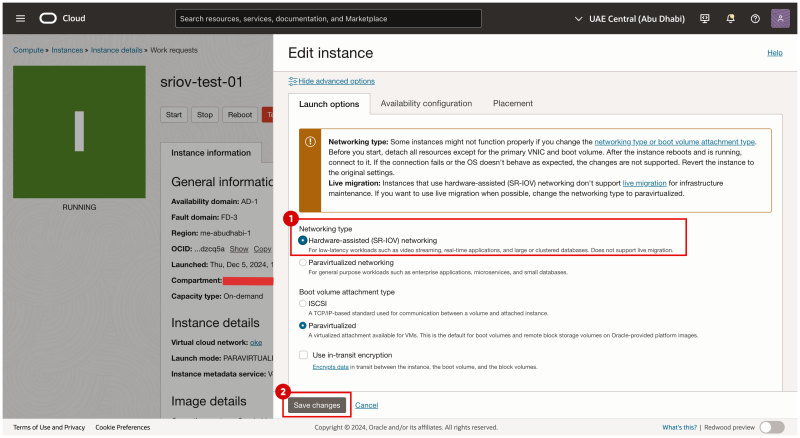
- In the Launch options tab select Networking-type: Hardware-assisted (SR-IOV) networking.
- Click on the Save changes button.
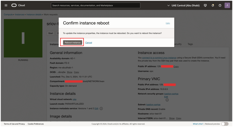
Click on the Reboot instance button to confirm the instance reboot.
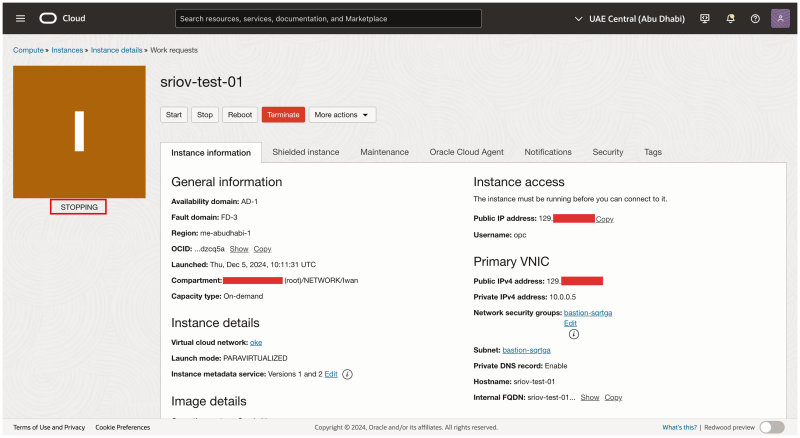
Notice that the Instance status has changed to STOPPING.
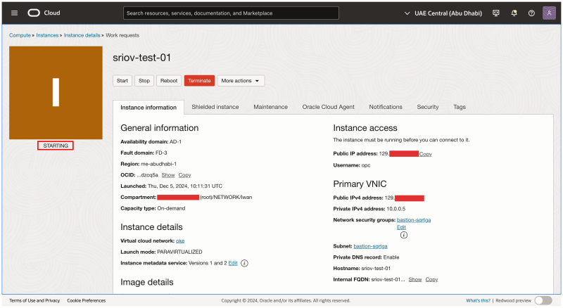
Notice that the Instance status has changed to STARTING.
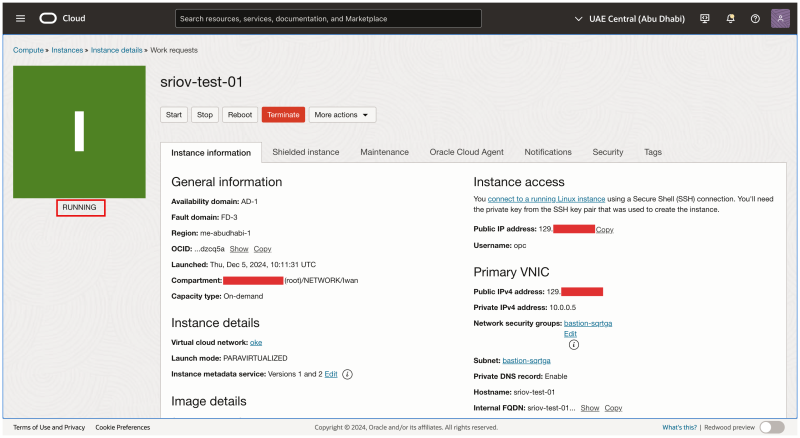
Notice that the Instance status has changed to RUNNING.
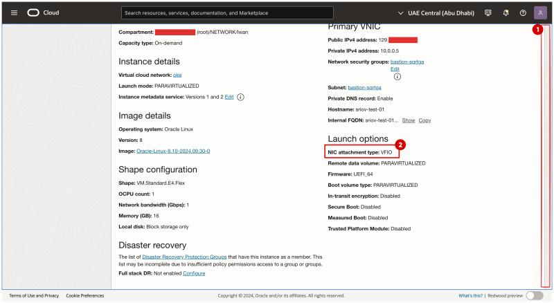
- Scroll down.
- Notice that the NIC attachment type is now VFIO.
The picture below is a visual overview of what we have configured so far.
STEP 03 - Create a new subnet for the sriov enabled VNICs
We are creating a dedicated subnet that our SR-IOV-enabled interfaces will use.
Security List
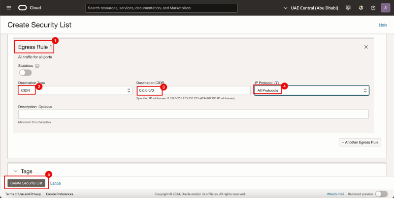
As we are already using Security Lists for the other subnets we will also create a dedicated security list for the newly created SR-IOV subnet.
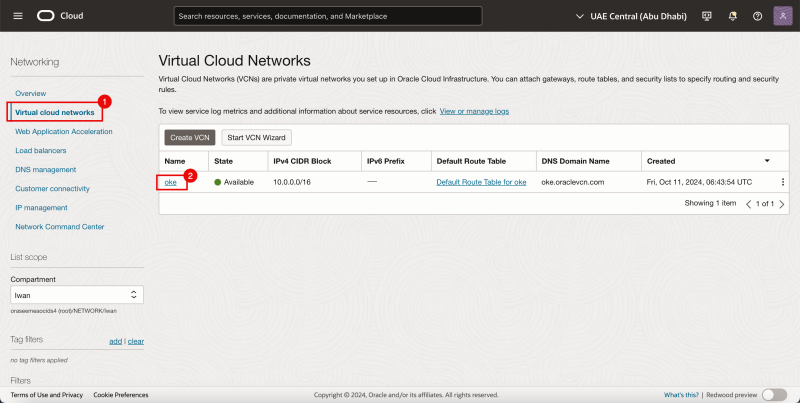
- Navigate to the Virtual Cloud Networks.
- Click on the existing VCN.
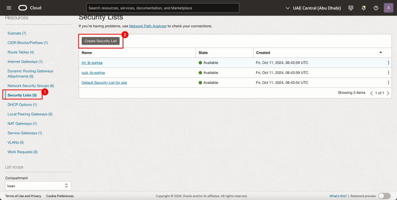
- Click on Security Lists.
- Click on the Create Security List Button
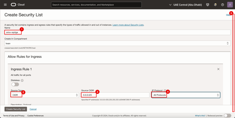
For the ingress Rule 1:
- Provide a name.
- Select CIDR for the Source Type.
- Specify 0.0.0.0/0 for the Source CIDR.
- Select All Protocols for the IP Protocol.
- Scroll down.
- For the ingress Rule 2:
- Select CIDR for the Source Type.
- Specify 0.0.0.0/0 for the Source CIDR.
- Select All Protocols for the IP Protocol.
- Click on the Create Security List button.
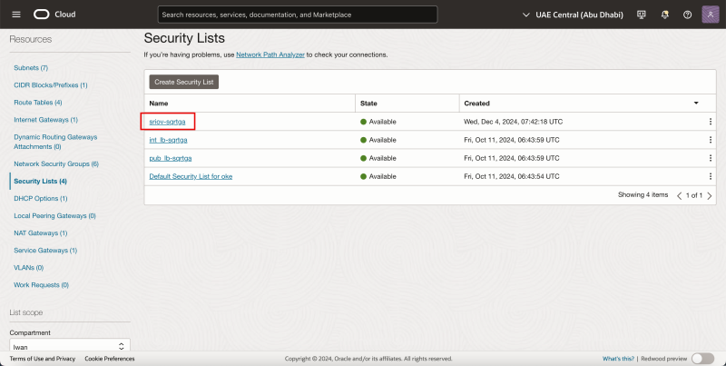
Notice that the new security list is created.
Subnet
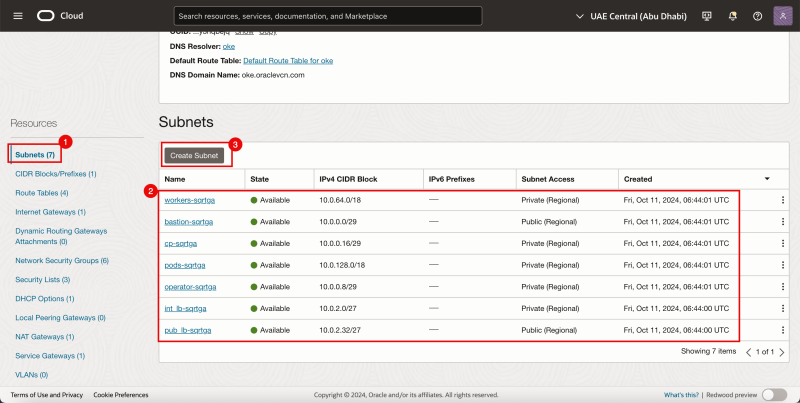
- In the same VCN click on Subnets.
- Notice the existing Subnets that are already created for our OKE Kubernetes OKE environment.
- Click on the Create Subnet button.
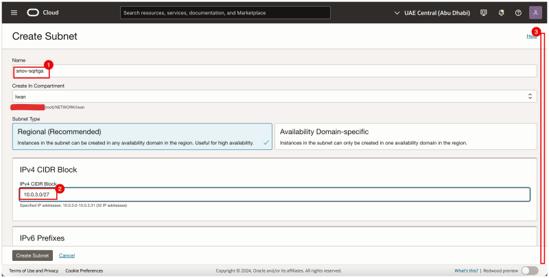
- Provide a name.
- Provide an IPv4 CIDR Block.
- Scroll down.
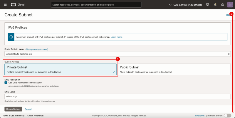
- Select Private Subnet.
- Scroll down.
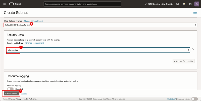
- Select the Default DHCP Options for DHCP Options.
- Select the Security List we just created.
- Click on the Create Subnet Button.
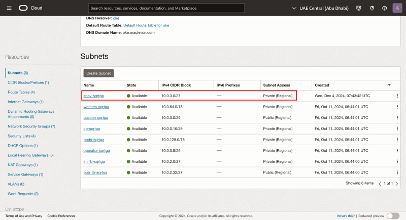
Notice that the net Subnet is created.
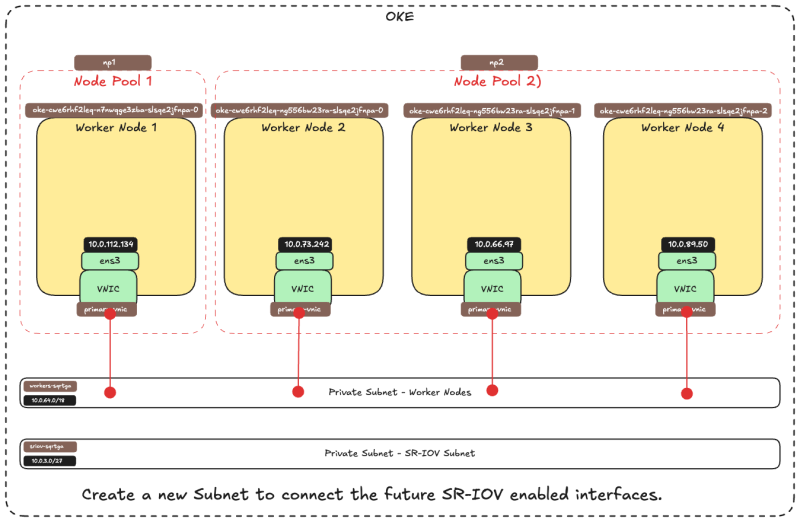
The Subnet itself does not have any SR-IOV-enabled technical components. In this tutorial we are using a standard OCI Subnet to allow the transport of traffic using the SR-IOV technology.
The picture below is a visual overview of what we have configured so far.
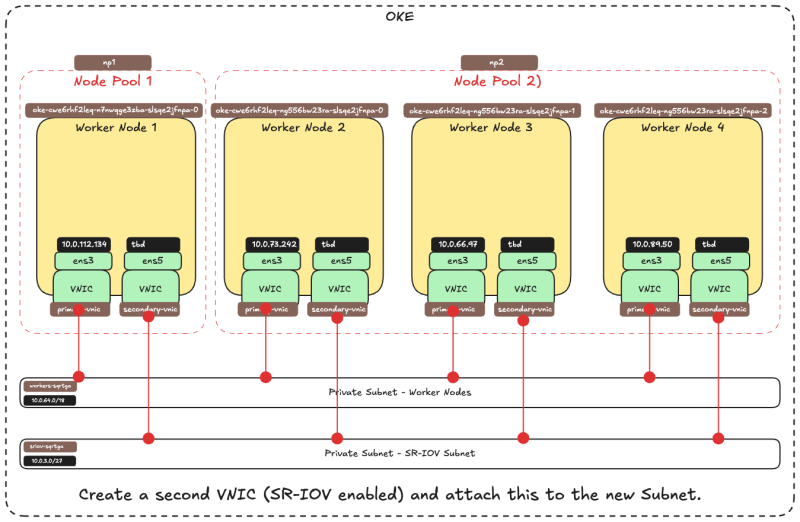
STEP 04 - Add a second VNIC Attachment
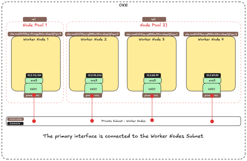
The picture below is a visual overview of how the Worker Nodes have a single VNIC that is connected to the Worker Nodes Subnet before we add a second VNIC.
Before we add a second VNIC attachment to the Worker Nodes let's first look at the prerequisites.
Network Security Groups
We are already using Network Security Groups (NSG) for the other vNICs and we will also create a dedicated Network Security Group (NSG) for the newly created vNIC that we will add to an existing Virtual Instance that is part of the OKE Cluster and that will play its part as an Kubernetes Worker Node. This interface will be a vNIC where we have SR-IOV enabled.
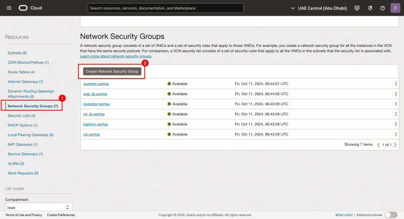
- Navigate to Network Security Groups (inside the VCN).
- Click on the Create Network Security Group button.
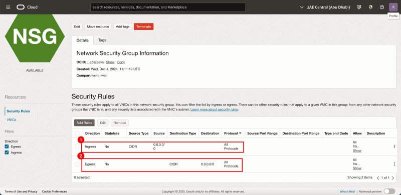
Add the following rules:
- Ingress: Allow Source Type: CIDR, Source: 0.0.0.0/0, Leave the Destination blank, and allow all protocols.
- Egress: Allow Source Type: CIDR, Leave the Source blank, Destination: 0.0.0.0/0, and allow all protocols.
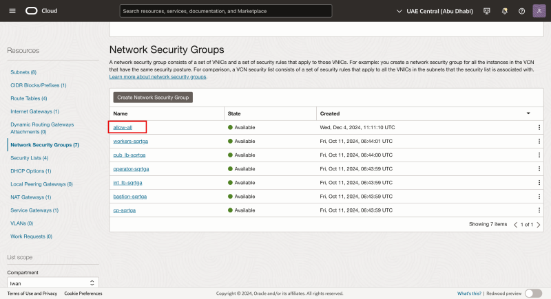
Notice that the NSG is created. We will apply it to the new (secondary) vNIC that we will create (on each worker node in the OKE cluster).
Adding the VNIC
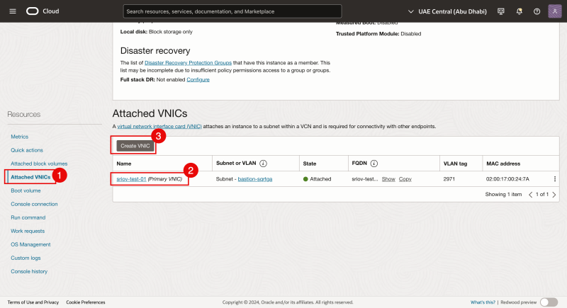
Navigate to each Virtual worker node Instance and add a second vNIC to each Worker Node.
- Navigate to each Virtual worker node Instance and click on Attached VNICs.
- Notice that there is already an existing VNIC.
- Click on the Create VNIC button to add a second VNIC.
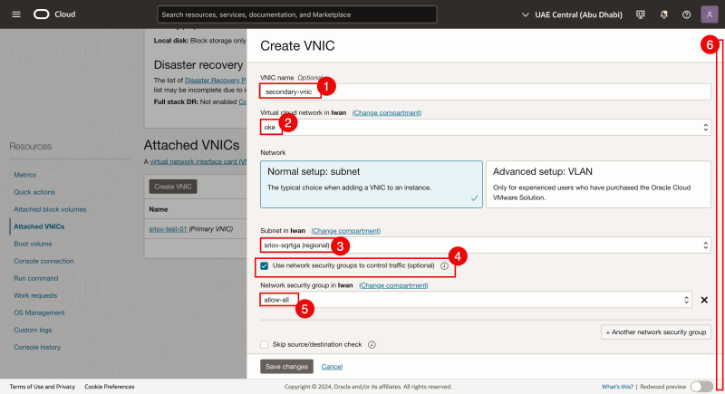
- Provide a name.
- Select the VCN.
- Select the subnet that we created earlier.
- Enable: Use network security groups to control traffic.
- Select the NSG that we created earlier.
- Scroll down.
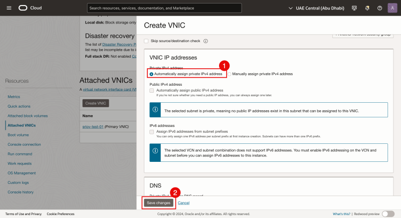
- Select Automatically assign private IPv4 address.
- Click on the Save changes button.
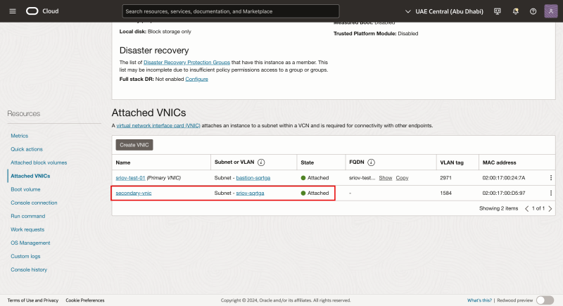
Notice that the second VNIC is created and attached to the Virtual Worker Node Instance and also attached to our subnet.
Log in with SSH to the Instance / Worker Node.
- Use the command
lspcito verify what network driver is currently used on all the VNICs. - Notice that the `Mellanox Technologies ConnectX Family mlx5Gen Virtual Function network driver is used.
The `Mellanox Technologies ConnectX Family mlx5Gen Virtual Function network driver is the Virtual Function (VF) driver that is used by SR-IOV. So the VNIC is enabled for SR-IOV with a VF.
The picture below is a visual overview of what we have configured so far.
STEP 05 - Assign an IP address to the new second VNIC with a default gateway
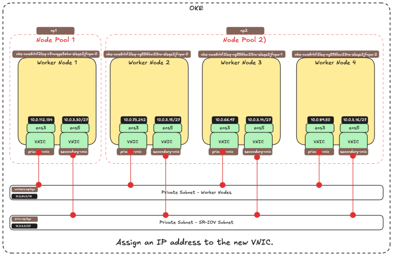
Now that the second VNIC has been created and attached we need to assign an IP address to it.
When you add a second interface to an instance you can assign it to the same subnet as the first interface, or you can pick a new subnet. DHCP is not enabled for the second interface so the IP address needs to be assigned manually. There are different methods of assigning the IP address of the second interface.
- Use OCI CLI (oci-utils) to assign an IP address to the second interface of an OCI Instance (using the [oci-network-config command])
- Use OCI CLI (oci-utils) to assign an IP address to the second interface of an OCI Instance (using the [ocid daemon])
- Use the [OCI_Multi_VNIC_Setup script]
- Create the interface config file manually for the new VNIC in the
/etc/sysconfig/network-scripts/folder.
For all worker nodes, we have assigned an IP address to the secondary vNIC (ens5). We used method 3 to assign an IP address to the secondary vNIC (ens5).
Use this tutorial to assign an IP address to the second VNIC: [Assign an IP Address to a Second Interface on an Oracle Linux Instance]
Once the IP address has been assigned to VNIC we need to verify if the IP address on the second VNICs are configured correctly. We can also verify if we enabled SR-IOV on all Node Pool Worker Nodes as well.
Our OKE cluster consists of :
| Node Pool | |
|---|---|
| NP1 | 1 x Worker Node |
| NP2 | 3 x Worker Nodes |
We will verify ALL worker nodes in ALL Node Pools.
NP1
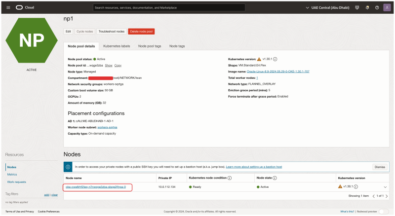
Inside the OKE cluster click on the Node Pools. Click on the first Node Pool (np1).
Click on the Worker Node that is part of this Node Pool.
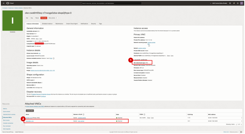
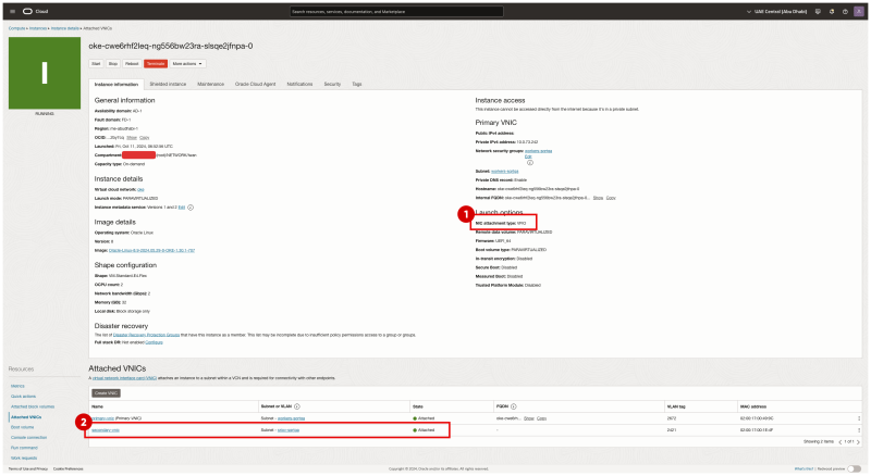
- Notice that the NIC attachment type is VFIO (this means that SR-IOV is enabled for this Virtual Instance WorkerNode).
- Notice that the second VNIC is created and attached for this worker node.
NP2
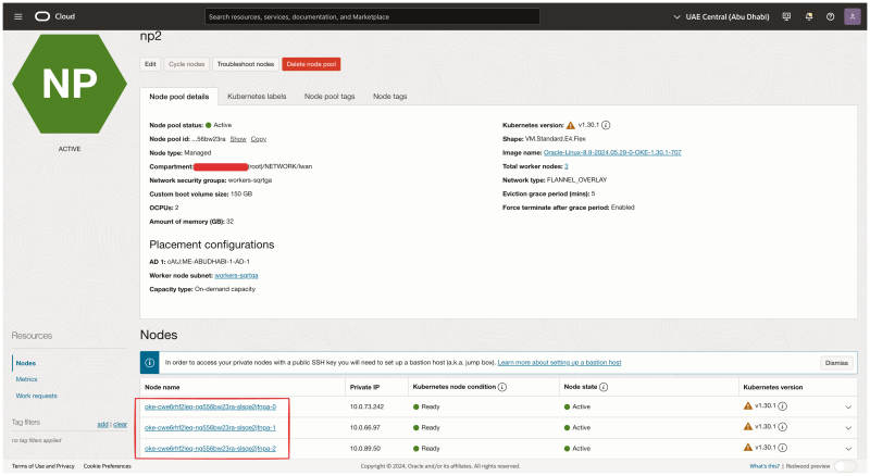
Now let's verify all the nodes in the second Node Pool (np2). Click on them one by one and start the verification.
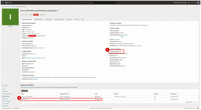
- Notice that the NIC attachment type is VFIO (this means that SR-IOV is enabled for this Virtual Instance WorkerNode).
- Notice that the second VNIC is created and attached for this worker node.
Go back to the np2 node pool summary. Click on the second worker node in the node pool.
- Notice that the NIC attachment type is VFIO (this means that SR-IOV is enabled for this Virtual Instance WorkerNode).
- Notice that the second VNIC is created and attached for this worker node.
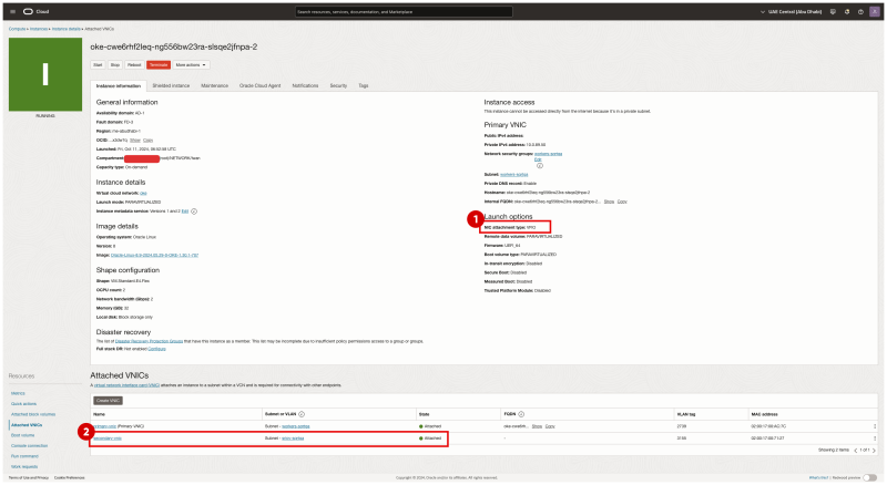
Go back to the np2 node pool summary. Click on the third worker node in the node pool.
- Notice that the NIC attachment type is VFIO (this means that SR-IOV is enabled for this Virtual Instance WorkerNode).
- Notice that the second VNIC is created and attached for this worker node.
Log in using SSH to the Kubernetes Operator.
Issue the command kubectl get nodes to retrieve a list and IP addresses of all the Worker Nodes.
[opc@o-sqrtga ~]$ kubectl get nodes
NAME           STATUS   ROLES   AGE   VERSION
10.0.112.134   Ready    node    68d   v1.30.1
10.0.66.97     Ready    node    68d   v1.30.1
10.0.73.242    Ready    node    68d   v1.30.1
10.0.89.50     Ready    node    68d   v1.30.1
[opc@o-sqrtga ~]$
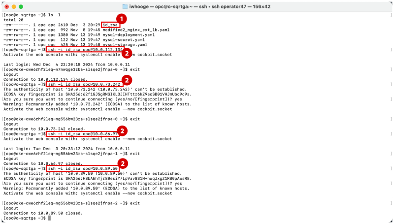
To make it easy to SSH into all the worker nodes I have created the table below:
| Worker Node Name | ens3 IP | SSH comand workernode |
|---|---|---|
| cwe6rhf2leq-n7nwqge3zba-slsqe2jfnpa-0 | 10.0.112.134 | ssh -i id_rsa opc@10.0.112.134
|
| cwe6rhf2leq-ng556bw23ra-slsqe2jfnpa-1 | 10.0.66.97 | ssh -i id_rsa opc@10.0.66.97
|
| cwe6rhf2leq-ng556bw23ra-slsqe2jfnpa-0 | 10.0.73.242 | ssh -i id_rsa opc@10.0.73.242
|
| cwe6rhf2leq-ng556bw23ra-slsqe2jfnpa-2 | 10.0.89.50 | ssh -i id_rsa opc@10.0.89.50
|
- Before you can SSH to all the Virtual Worker Nodes make sure you have the correct private key available.
- Use the command
ssh -i <private key> opc@<ip-address>to SSH into all the worker nodes.
Issue the command ip a on the cwe6rhf2leq-n7nwqge3zba-slsqe2jfnpa-0 Worker Node.
Notice that when the IP address has been successfully configured the ens5 (second VNIC) has an IP address in the range of the subnet we created earlier for the SR-IOV interfaces.
[opc@oke-cwe6rhf2leq-n7nwqge3zba-slsqe2jfnpa-0 ~]$ ip a
1: lo: <LOOPBACK,UP,LOWER_UP> mtu 65536 qdisc noqueue state UNKNOWN group default qlen 1000
    link/loopback 00:00:00:00:00:00 brd 00:00:00:00:00:00
    inet 127.0.0.1/8 scope host lo
       valid_lft forever preferred_lft forever
    inet6 ::1/128 scope host
       valid_lft forever preferred_lft forever
2: ens3: <BROADCAST,MULTICAST,UP,LOWER_UP> mtu 9000 qdisc mq state UP group default qlen 1000
    link/ether 02:00:17:00:59:58 brd ff:ff:ff:ff:ff:ff
    altname enp0s3
    inet 10.0.112.134/18 brd 10.0.127.255 scope global dynamic ens3
       valid_lft 85530sec preferred_lft 85530sec
    inet6 fe80::17ff:fe00:5958/64 scope link
       valid_lft forever preferred_lft forever
3: ens5: <BROADCAST,MULTICAST,UP,LOWER_UP> mtu 9000 qdisc mq state UP group default qlen 1000
    link/ether 02:00:17:00:d4:a2 brd ff:ff:ff:ff:ff:ff
    altname enp0s5
    inet 10.0.3.30/27 brd 10.0.3.31 scope global noprefixroute ens5
       valid_lft forever preferred_lft forever
    inet6 fe80::8106:c09e:61fa:1d2a/64 scope link noprefixroute
       valid_lft forever preferred_lft forever
4: flannel.1: <BROADCAST,MULTICAST,UP,LOWER_UP> mtu 8950 qdisc noqueue state UNKNOWN group default
    link/ether 3a:b7:fb:e6:2e:cf brd ff:ff:ff:ff:ff:ff
    inet 10.244.1.0/32 scope global flannel.1
       valid_lft forever preferred_lft forever
    inet6 fe80::38b7:fbff:fee6:2ecf/64 scope link
       valid_lft forever preferred_lft forever
5: cni0: <BROADCAST,MULTICAST,UP,LOWER_UP> mtu 8950 qdisc noqueue state UP group default qlen 1000
    link/ether de:35:f5:51:85:5d brd ff:ff:ff:ff:ff:ff
    inet 10.244.1.1/25 brd 10.244.1.127 scope global cni0
       valid_lft forever preferred_lft forever
    inet6 fe80::dc35:f5ff:fe51:855d/64 scope link
       valid_lft forever preferred_lft forever
6: veth1cdaac17@if2: <BROADCAST,MULTICAST,UP,LOWER_UP> mtu 8950 qdisc noqueue master cni0 state UP group default
    link/ether 76:e2:92:ad:37:40 brd ff:ff:ff:ff:ff:ff link-netns 1935ba66-34cc-4468-8abb-f66add46d08b
    inet6 fe80::74e2:92ff:fead:3740/64 scope link
       valid_lft forever preferred_lft forever
7: vethbcd391ab@if2: <BROADCAST,MULTICAST,UP,LOWER_UP> mtu 8950 qdisc noqueue master cni0 state UP group default
    link/ether 9a:9a:0f:d6:48:17 brd ff:ff:ff:ff:ff:ff link-netns 3f02d5fd-596e-4b9f-8a35-35f2f946901b
    inet6 fe80::989a:fff:fed6:4817/64 scope link
       valid_lft forever preferred_lft forever
8: vethc15fa705@if2: <BROADCAST,MULTICAST,UP,LOWER_UP> mtu 8950 qdisc noqueue master cni0 state UP group default
    link/ether 3a:d2:c8:66:d1:0b brd ff:ff:ff:ff:ff:ff link-netns f581b7f2-cfa0-46eb-b0aa-37001a11116d
    inet6 fe80::38d2:c8ff:fe66:d10b/64 scope link
       valid_lft forever preferred_lft forever
[opc@oke-cwe6rhf2leq-n7nwqge3zba-slsqe2jfnpa-0 ~]$
Issue the command ip a on the cwe6rhf2leq-ng556bw23ra-slsqe2jfnpa-1 Worker Node.
Notice that when the IP address has been successfully configured the ens5 (second VNIC) has an IP address in the range of the subnet we created earlier for the SR-IOV interfaces.
[opc@oke-cwe6rhf2leq-ng556bw23ra-slsqe2jfnpa-1 ~]$ ip a
1: lo: <LOOPBACK,UP,LOWER_UP> mtu 65536 qdisc noqueue state UNKNOWN group default qlen 1000
    link/loopback 00:00:00:00:00:00 brd 00:00:00:00:00:00
    inet 127.0.0.1/8 scope host lo
       valid_lft forever preferred_lft forever
    inet6 ::1/128 scope host
       valid_lft forever preferred_lft forever
2: ens3: <BROADCAST,MULTICAST,UP,LOWER_UP> mtu 9000 qdisc mq state UP group default qlen 1000
    link/ether 02:00:17:00:16:ca brd ff:ff:ff:ff:ff:ff
    altname enp0s3
    inet 10.0.66.97/18 brd 10.0.127.255 scope global dynamic ens3
       valid_lft 85859sec preferred_lft 85859sec
    inet6 fe80::17ff:fe00:16ca/64 scope link
       valid_lft forever preferred_lft forever
3: ens5: <BROADCAST,MULTICAST,UP,LOWER_UP> mtu 9000 qdisc mq state UP group default qlen 1000
    link/ether 02:00:17:00:7b:4f brd ff:ff:ff:ff:ff:ff
    altname enp0s5
    inet 10.0.3.15/27 brd 10.0.3.31 scope global noprefixroute ens5
       valid_lft forever preferred_lft forever
    inet6 fe80::87eb:4195:cacf:a6da/64 scope link noprefixroute
       valid_lft forever preferred_lft forever
4: flannel.1: <BROADCAST,MULTICAST,UP,LOWER_UP> mtu 8950 qdisc noqueue state UNKNOWN group default
    link/ether 02:92:e7:f5:8e:29 brd ff:ff:ff:ff:ff:ff
    inet 10.244.1.128/32 scope global flannel.1
       valid_lft forever preferred_lft forever
    inet6 fe80::92:e7ff:fef5:8e29/64 scope link
       valid_lft forever preferred_lft forever
5: cni0: <BROADCAST,MULTICAST,UP,LOWER_UP> mtu 8950 qdisc noqueue state UP group default qlen 1000
    link/ether f6:08:06:e2:bc:9d brd ff:ff:ff:ff:ff:ff
    inet 10.244.1.129/25 brd 10.244.1.255 scope global cni0
       valid_lft forever preferred_lft forever
    inet6 fe80::f408:6ff:fee2:bc9d/64 scope link
       valid_lft forever preferred_lft forever
6: veth5db97290@if2: <BROADCAST,MULTICAST,UP,LOWER_UP> mtu 8950 qdisc noqueue master cni0 state UP group default
    link/ether c2:e0:b5:7e:ce:ed brd ff:ff:ff:ff:ff:ff link-netns 3682b5cd-9039-4931-aecc-b50d46dabaf1
    inet6 fe80::c0e0:b5ff:fe7e:ceed/64 scope link
       valid_lft forever preferred_lft forever
7: veth6fd818a5@if2: <BROADCAST,MULTICAST,UP,LOWER_UP> mtu 8950 qdisc noqueue master cni0 state UP group default
    link/ether 3e:a8:7d:84:d3:b9 brd ff:ff:ff:ff:ff:ff link-netns 08141d6b-5ec0-4f3f-a312-a00b30f82ade
    inet6 fe80::3ca8:7dff:fe84:d3b9/64 scope link
       valid_lft forever preferred_lft forever
[opc@oke-cwe6rhf2leq-ng556bw23ra-slsqe2jfnpa-1 ~]$
Issue the command ip a on the cwe6rhf2leq-ng556bw23ra-slsqe2jfnpa-0 Worker Node.
Notice that when the IP address has been successfully configured the ens5 (second VNIC) has an IP address in the range of the subnet we created earlier for the SR-IOV interfaces.
[opc@oke-cwe6rhf2leq-ng556bw23ra-slsqe2jfnpa-0 ~]$ ip a
1: lo: <LOOPBACK,UP,LOWER_UP> mtu 65536 qdisc noqueue state UNKNOWN group default qlen 1000
    link/loopback 00:00:00:00:00:00 brd 00:00:00:00:00:00
    inet 127.0.0.1/8 scope host lo
       valid_lft forever preferred_lft forever
    inet6 ::1/128 scope host
       valid_lft forever preferred_lft forever
2: ens3: <BROADCAST,MULTICAST,UP,LOWER_UP> mtu 9000 qdisc mq state UP group default qlen 1000
    link/ether 02:00:17:00:49:9c brd ff:ff:ff:ff:ff:ff
    altname enp0s3
    inet 10.0.73.242/18 brd 10.0.127.255 scope global dynamic ens3
       valid_lft 86085sec preferred_lft 86085sec
    inet6 fe80::17ff:fe00:499c/64 scope link
       valid_lft forever preferred_lft forever
3: ens5: <BROADCAST,MULTICAST,UP,LOWER_UP> mtu 9000 qdisc mq state UP group default qlen 1000
    link/ether 02:00:17:00:b7:51 brd ff:ff:ff:ff:ff:ff
    altname enp0s5
    inet 10.0.3.14/27 brd 10.0.3.31 scope global noprefixroute ens5
       valid_lft forever preferred_lft forever
    inet6 fe80::bc31:aa09:4e05:9ab7/64 scope link noprefixroute
       valid_lft forever preferred_lft forever
4: flannel.1: <BROADCAST,MULTICAST,UP,LOWER_UP> mtu 8950 qdisc noqueue state UNKNOWN group default
    link/ether 9a:c7:1b:30:e8:9a brd ff:ff:ff:ff:ff:ff
    inet 10.244.0.0/32 scope global flannel.1
       valid_lft forever preferred_lft forever
    inet6 fe80::98c7:1bff:fe30:e89a/64 scope link
       valid_lft forever preferred_lft forever
5: cni0: <BROADCAST,MULTICAST,UP,LOWER_UP> mtu 8950 qdisc noqueue state UP group default qlen 1000
    link/ether 2a:2b:cb:fb:15:82 brd ff:ff:ff:ff:ff:ff
    inet 10.244.0.1/25 brd 10.244.0.127 scope global cni0
       valid_lft forever preferred_lft forever
    inet6 fe80::282b:cbff:fefb:1582/64 scope link
       valid_lft forever preferred_lft forever
6: veth06343057@if2: <BROADCAST,MULTICAST,UP,LOWER_UP> mtu 8950 qdisc noqueue master cni0 state UP group default
    link/ether ca:70:83:13:dc:ed brd ff:ff:ff:ff:ff:ff link-netns fb0f181f-7c3a-4fb6-8bf0-5a65d39486c1
    inet6 fe80::c870:83ff:fe13:dced/64 scope link
       valid_lft forever preferred_lft forever
7: veth8af17165@if2: <BROADCAST,MULTICAST,UP,LOWER_UP> mtu 8950 qdisc noqueue master cni0 state UP group default
    link/ether c6:a0:be:75:9b:d9 brd ff:ff:ff:ff:ff:ff link-netns c07346e6-33f5-4e80-ba5e-74f7487b5daa
    inet6 fe80::c4a0:beff:fe75:9bd9/64 scope link
       valid_lft forever preferred_lft forever
[opc@oke-cwe6rhf2leq-ng556bw23ra-slsqe2jfnpa-0 ~]$
Issue the command ip a on the cwe6rhf2leq-ng556bw23ra-slsqe2jfnpa-2 Worker Node.
Notice that when the IP address has been successfully configured the ens5 (second VNIC) has an IP address in the range of the subnet we created earlier for the SR-IOV interfaces.
[opc@oke-cwe6rhf2leq-ng556bw23ra-slsqe2jfnpa-2 ~]$ ip a
1: lo: <LOOPBACK,UP,LOWER_UP> mtu 65536 qdisc noqueue state UNKNOWN group default qlen 1000
    link/loopback 00:00:00:00:00:00 brd 00:00:00:00:00:00
    inet 127.0.0.1/8 scope host lo
       valid_lft forever preferred_lft forever
    inet6 ::1/128 scope host
       valid_lft forever preferred_lft forever
2: ens3: <BROADCAST,MULTICAST,UP,LOWER_UP> mtu 9000 qdisc mq state UP group default qlen 1000
    link/ether 02:00:17:00:ac:7c brd ff:ff:ff:ff:ff:ff
    altname enp0s3
    inet 10.0.89.50/18 brd 10.0.127.255 scope global dynamic ens3
       valid_lft 86327sec preferred_lft 86327sec
    inet6 fe80::17ff:fe00:ac7c/64 scope link
       valid_lft forever preferred_lft forever
3: ens5: <BROADCAST,MULTICAST,UP,LOWER_UP> mtu 9000 qdisc mq state UP group default qlen 1000
    link/ether 02:00:17:00:4c:0d brd ff:ff:ff:ff:ff:ff
    altname enp0s5
    inet 10.0.3.16/27 brd 10.0.3.31 scope global noprefixroute ens5
       valid_lft forever preferred_lft forever
    inet6 fe80::91eb:344e:829e:35de/64 scope link noprefixroute
       valid_lft forever preferred_lft forever
4: flannel.1: <BROADCAST,MULTICAST,UP,LOWER_UP> mtu 8950 qdisc noqueue state UNKNOWN group default
    link/ether aa:31:9f:d0:b3:3c brd ff:ff:ff:ff:ff:ff
    inet 10.244.0.128/32 scope global flannel.1
       valid_lft forever preferred_lft forever
    inet6 fe80::a831:9fff:fed0:b33c/64 scope link
       valid_lft forever preferred_lft forever
5: cni0: <BROADCAST,MULTICAST,UP,LOWER_UP> mtu 8950 qdisc noqueue state UP group default qlen 1000
    link/ether b2:0d:c0:de:02:61 brd ff:ff:ff:ff:ff:ff
    inet 10.244.0.129/25 brd 10.244.0.255 scope global cni0
       valid_lft forever preferred_lft forever
    inet6 fe80::b00d:c0ff:fede:261/64 scope link
       valid_lft forever preferred_lft forever
6: vethb37e8987@if2: <BROADCAST,MULTICAST,UP,LOWER_UP> mtu 8950 qdisc noqueue master cni0 state UP group default
    link/ether 7a:93:1d:2a:33:8c brd ff:ff:ff:ff:ff:ff link-netns ab3262ca-4a80-4b02-a39f-4209d003f148
    inet6 fe80::7893:1dff:fe2a:338c/64 scope link
       valid_lft forever preferred_lft forever
7: veth73a651ce@if2: <BROADCAST,MULTICAST,UP,LOWER_UP> mtu 8950 qdisc noqueue master cni0 state UP group default
    link/ether ae:e4:97:89:ba:6e brd ff:ff:ff:ff:ff:ff link-netns 9307bfbd-8165-46bf-916c-e1180b6cbd83
    inet6 fe80::ace4:97ff:fe89:ba6e/64 scope link
       valid_lft forever preferred_lft forever
[opc@oke-cwe6rhf2leq-ng556bw23ra-slsqe2jfnpa-2 ~]$
Now that we have verified is all the IP addresses are configured on the second VNIC (ens5) we can create the table below:
| ens3 IP | ens3 GW | ens5 IP | ens5 GW |
|---|---|---|---|
| 10.0.112.134 | 10.0.64.1 | 10.0.3.30/27 | 10.0.3.1 |
| 10.0.66.97 | 10.0.64.1 | 10.0.3.15/27 | 10.0.3.1 |
| 10.0.73.242 | 10.0.64.1 | 10.0.3.14/27 | 10.0.3.1 |
| 10.0.89.50 | 10.0.64.1 | 10.0.3.16/27 | 10.0.3.1 |
The picture below is a visual overview of what we have configured so far.
STEP 06 - Install a Meta-Plugin CNI -Multus- on the worker node
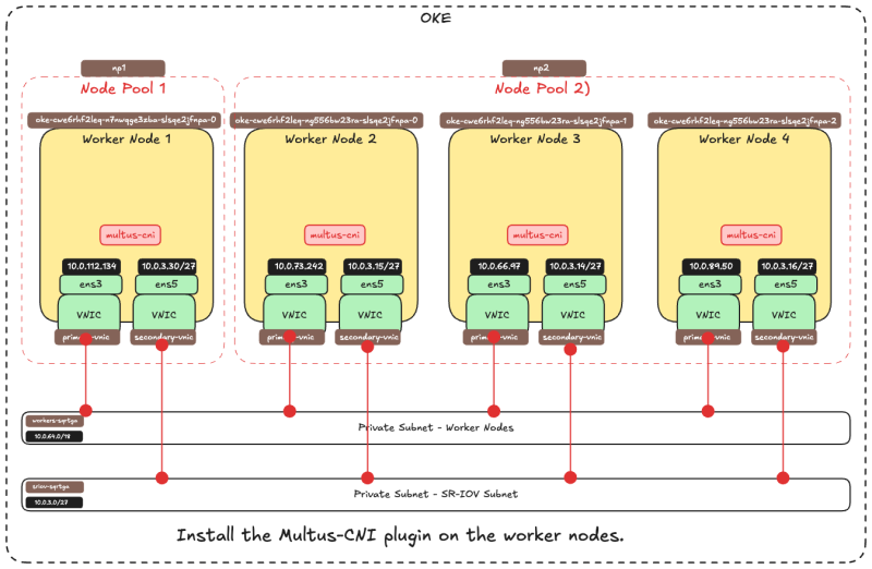
Now that we have an IP address on the second VNIC of all the worker nodes, we can install the Multus (Meta) CNI plugin on each Worker Node.
Multus CNI is a Kubernetes Container Network Interface (CNI) plugin that allows you to attach multiple network interfaces to a pod.
How It Works
- Acts as a meta-plugin – Multus doesn’t provide networking itself but instead calls other CNI plugins.
- Creates multiple network interfaces – Each pod can have more than one network interface by combining multiple CNI plugins (e.g., Flannel, Calico, SR-IOV).
- Uses a configuration file – The primary network is set up via the default CNI, and additional networks are attached based on a custom CRD (Custom Resource Definition).
Why We Need It
- Multiple Network Isolation – Useful for workloads that require separate management and data planes.
- High-Performance Networking – Enables direct hardware access using SR-IOV or DPDK.
- Multi-Homing for Pods – Supports NFV (Network Function Virtualization) and Telco use cases where multiple network interfaces are essential.
Installing Multus (thin install method)
SSH into the Kubernetes Operator.
- Use this command to clone the Multus Git library:
git clone https://github.com/k8snetworkplumbingwg/multus-cni.git && cd multus-cni. - Use this command to install the Multus daemon set using the thin install method:
kubectl apply -f deployments/multus-daemonset.yml && cd ..
What the Multus daemon set does:
- Starts a Multus daemon set, this runs a pod on each node which places a Multus binary on each node in
/opt/cni/bin - Reads the lexicographically (alphabetically) first configuration file in
/etc/cni/net.d, and creates a new configuration file for Multus on each node as/etc/cni/net.d/00-multus.conf, this configuration is auto-generated and is based on the default network configuration (which is assumed to be the alphabetically first configuration) - Creates a
/etc/cni/net.d/multus.ddirectory on each node with authentication information for Multus to access the Kubernetes API.
Validating the installation:
- Use this command (on the Kubernetes operator) to validate if the Multus daemon set is installed on all worker nodes:
kubectl get pods --all-namespaces | grep -i multus.
You can also verify if the Multus daemon set is installed on the Worker Nodes itself.
- SSH into the worker node with the following command:
ssh -i id_rsa opc@10.0.112.134. - Change the directory with the following command:
cd /etc/cni/net.d/. - List the directory output with the following command:
ls -l. - Notice that the
00-multus.confand themultus.dfiles are there.
- Issue this command to look at the content of the
00-multus.conffile:sudo more 00-multus.conf. - Notice the content of the
00-multus.conffile.
STEP 07 - Attach network interfaces to PODs
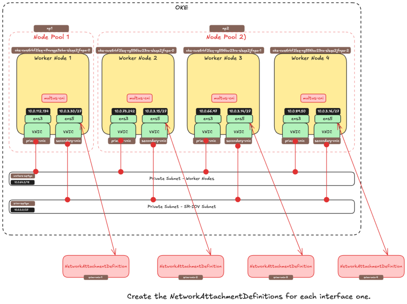
Now that we have the IP address assigned to the second VNIC and we have installed Multus we will have "map" or "attach" a container interface to this VNIC.
- To attach additional interfaces to pods, we need a configuration for the interface to be attached.
- This is encapsulated in the custom resource of kind
NetworkAttachmentDefinition. - This configuration is essentially a CNI configuration packaged as a custom resource.
- There are [several CNI plugins] that can be used alongside Multus to accomplish this.
- In the approach described here, the goal is to provide an SR-IOV Virtual Function exclusively for a single pod, so that the pod can take advantage of the capabilities without interference or any layers in between.
- To grant a pod exclusive access to the VF, we can leverage the [host-device plug-in] that enables you to move the interface into the pod’s namespace so that it has exclusive access to it.
- The examples below show
NetworkAttachmentDefinitionobjects that configure the secondaryens5interface that was added to the nodes. - The
ipamplug-in configuration determines how IP addresses are managed for these interfaces. - In this example, as we want to use the same IP addresses that were assigned to the secondary interfaces by OCI, we use the static
ipamconfiguration with the appropriate routes. - The
ipamconfiguration also supports other methods likehost-localordhcpfor more flexible configurations.
Create network attachment definition
The 'NetworkAttachmentDefinition' is used to set up the network attachment, i.e. secondary interface for the pod.
There are two ways to configure the 'NetworkAttachmentDefinition' as follows:
- NetworkAttachmentDefinition with json CNI config
- NetworkAttachmentDefinition with CNI config file
In this tutorial, we are going to use the method using the CNI config file
NetworkAttachmentDefinition with CNI config file:
We have 4 x worker nodes and each worker node has a second VNIC that we will map to an interface on a container (POD). Below are the commands to create the CNI config files for all worker nodes and corresponding VNICs.
| ens3 | ens5 | name | network | nano command |
|---|---|---|---|---|
| 10.0.112.134 | 10.0.3.30/27 | sriov-vnic-1 | 10.0.3.0/27 | sudo nano sriov-vnic-1.yaml
|
| 10.0.66.97 | 10.0.3.15/27 | sriov-vnic-2 | 10.0.3.0/27 | sudo nano sriov-vnic-2.yaml
|
| 10.0.73.242 | 10.0.3.14/27 | sriov-vnic-3 | 10.0.3.0/27 | sudo nano sriov-vnic-3.yaml
|
| 10.0.89.50 | 10.0.3.16/27 | sriov-vnic-4 | 10.0.3.0/27 | sudo nano sriov-vnic-4.yaml
|
Perform the following on the Kubernetes operator.
Create a new YAML file for the first Worker Node using this command sudo nano sriov-vnic-1.yaml
The content of the sriov-vnic-1.yaml file (for the first worker node) can be found below:
- Make sure the name is unique and descriptive (we are using
sriov-vnic-1. - Use the IP address of the second adapter you just added (ens5).
- Make sure the
dst networkis also correct (this is the same as the subnet that we created in OCI).
sriov-vnic-1.yaml
apiVersion: "k8s.cni.cncf.io/v1"
kind: NetworkAttachmentDefinition
metadata:
  name: sriov-vnic-1
spec:
  config: '{
        "cniVersion": "0.3.1",
        "type": "host-device",
        "device": "ens5",
        "ipam": {
                "type": "static",
                "addresses": [
                    {
                        "address": "10.0.3.30/27",
                        "gateway": "0.0.0.0"
                    }
                ],
                "routes": [
                    { "dst": "10.0.3.0/27", "gw": "0.0.0.0" }
                ]
            }
          }'
Create a new YAML file for the first Worker Node using this command sudo nano sriov-vnic-2.yaml
The content of the sriov-vnic-2.yaml file (for the first worker node) can be found below:
sriov-vnic-2.yaml
apiVersion: "k8s.cni.cncf.io/v1"
kind: NetworkAttachmentDefinition
metadata:
  name: sriov-vnic-2
spec:
  config: '{
        "cniVersion": "0.3.1",
        "type": "host-device",
        "device": "ens5",
        "ipam": {
                "type": "static",
                "addresses": [
                    {
                        "address": "10.0.3.15/27",
                        "gateway": "0.0.0.0"
                    }
                ],
                "routes": [
                    { "dst": "10.0.3.0/27", "gw": "0.0.0.0" }
                ]
            }
          }'
Create a new YAML file for the first Worker Node using this command sudo nano sriov-vnic-3.yaml
The content of the sriov-vnic-3.yaml file (for the first worker node) can be found below:
sriov-vnic-3.yaml
apiVersion: "k8s.cni.cncf.io/v1"
kind: NetworkAttachmentDefinition
metadata:
  name: sriov-vnic-3
spec:
  config: '{
        "cniVersion": "0.3.1",
        "type": "host-device",
        "device": "ens5",
        "ipam": {
                "type": "static",
                "addresses": [
                    {
                        "address": "10.0.3.14/27",
                        "gateway": "0.0.0.0"
                    }
                ],
                "routes": [
                    { "dst": "10.0.3.0/27", "gw": "0.0.0.0" }
                ]
            }
          }'
Create a new YAML file for the first Worker Node using this command sudo nano sriov-vnic-4.yaml
The content of the sriov-vnic-4.yaml file (for the first worker node) can be found below:
sriov-vnic-4.yaml
apiVersion: "k8s.cni.cncf.io/v1"
kind: NetworkAttachmentDefinition
metadata:
  name: sriov-vnic-4
spec:
  config: '{
        "cniVersion": "0.3.1",
        "type": "host-device",
        "device": "ens5",
        "ipam": {
                "type": "static",
                "addresses": [
                    {
                        "address": "10.0.3.16/27",
                        "gateway": "0.0.0.0"
                    }
                ],
                "routes": [
                    { "dst": "10.0.3.0/27", "gw": "0.0.0.0" }
                ]
            }
          }'
Apply the NetworkAttachmentDefinition to the Worker Nodes.
- For the first node issue this command
kubectl apply -f sriov-vnic-1.yaml - For the first node issue this command
kubectl apply -f sriov-vnic-2.yaml - For the first node issue this command
kubectl apply -f sriov-vnic-3.yaml - For the first node issue this command
kubectl apply -f sriov-vnic-4.yaml
If the NetworkAttachmentDefinition is correctly applied you will see something similar to the output below.
[opc@o-sqrtga ~]$ kubectl apply -f sriov-vnic-1.yaml
networkattachmentdefinition.k8s.cni.cncf.io/sriov-vnic-1 created
[opc@o-sqrtga ~]$ kubectl apply -f sriov-vnic-2.yaml
networkattachmentdefinition.k8s.cni.cncf.io/sriov-vnic-2 created
[opc@o-sqrtga ~]$ kubectl apply -f sriov-vnic-3.yaml
networkattachmentdefinition.k8s.cni.cncf.io/sriov-vnic-3 created
[opc@o-sqrtga ~]$ kubectl apply -f sriov-vnic-4.yaml
networkattachmentdefinition.k8s.cni.cncf.io/sriov-vnic-4 created
[opc@o-sqrtga ~]$
Issue this command to verify if the NetworkAttachmentDefinitions are applied correctly: kubectl get network-attachment-definitions.k8s.cni.cncf.io
[opc@o-sqrtga ~]$ kubectl get network-attachment-definitions.k8s.cni.cncf.io
NAME           AGE
sriov-vnic-1   96s
sriov-vnic-2   72s
sriov-vnic-3   60s
sriov-vnic-4   48s
[opc@o-sqrtga ~]$
Issue the following command to get the applied NetworkAttachmentDefinition for the first worker node: kubectl get networkattachmentdefinition.k8s.cni.cncf.io/sriov-vnic-1 -o yaml
[opc@o-sqrtga ~]$ kubectl get networkattachmentdefinition.k8s.cni.cncf.io/sriov-vnic-1 -o yaml
apiVersion: k8s.cni.cncf.io/v1
kind: NetworkAttachmentDefinition
metadata:
  annotations:
    kubectl.kubernetes.io/last-applied-configuration:
Issue the following command to get the applied NetworkAttachmentDefinition for the second worker node: kubectl get networkattachmentdefinition.k8s.cni.cncf.io/sriov-vnic-2 -o yaml
[opc@o-sqrtga ~]$ kubectl get networkattachmentdefinition.k8s.cni.cncf.io/sriov-vnic-2 -o yaml
apiVersion: k8s.cni.cncf.io/v1
kind: NetworkAttachmentDefinition
metadata:
  annotations:
    kubectl.kubernetes.io/last-applied-configuration:
Issue the following command to get the applied NetworkAttachmentDefinition for the third worker node: kubectl get networkattachmentdefinition.k8s.cni.cncf.io/sriov-vnic-3 -o yaml
[opc@o-sqrtga ~]$ kubectl get networkattachmentdefinition.k8s.cni.cncf.io/sriov-vnic-3 -o yaml
apiVersion: k8s.cni.cncf.io/v1
kind: NetworkAttachmentDefinition
metadata:
  annotations:
    kubectl.kubernetes.io/last-applied-configuration:
Issue the following command to get the applied NetworkAttachmentDefinition for the fourth worker node: kubectl get networkattachmentdefinition.k8s.cni.cncf.io/sriov-vnic-4 -o yaml
[opc@o-sqrtga ~]$ kubectl get networkattachmentdefinition.k8s.cni.cncf.io/sriov-vnic-4 -o yaml
apiVersion: k8s.cni.cncf.io/v1
kind: NetworkAttachmentDefinition
metadata:
  annotations:
    kubectl.kubernetes.io/last-applied-configuration:
The picture below is a visual overview of what we have configured so far.
Creating the PODS with the NetworkDefinitionAttachment attached
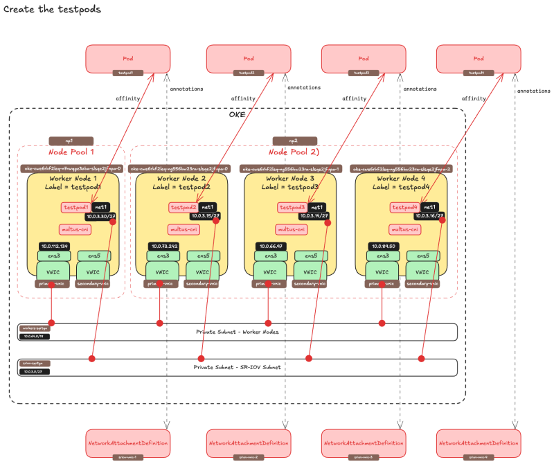
Now it is time to "tie" the NetworkAttachmentDefinitions to an actual container or POD. Below I have created a mapping on what POD I want to host on what worker node.
| Worker (Primary) Node IP | ens5 | name | pod name | finished |
|---|---|---|---|---|
| 10.0.112.134 | 10.0.3.30/27 | sriov-vnic-1 | testpod1 | YES |
| 10.0.66.97 | 10.0.3.15/27 | sriov-vnic-2 | testpod2 | YES |
| 10.0.73.242 | 10.0.3.14/27 | sriov-vnic-3 | testpod3 | YES |
| 10.0.89.50 | 10.0.3.16/27 | sriov-vnic-4 | testpod4 | YES |
Create PODs with Node Affinity
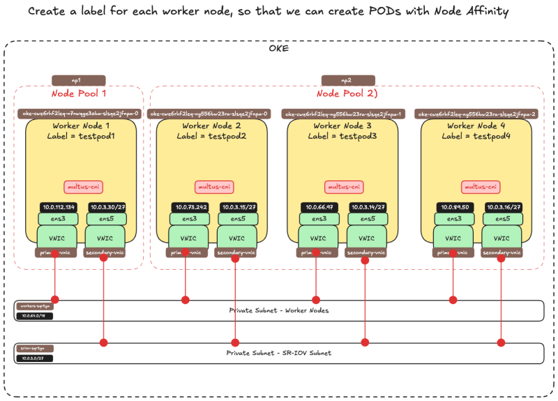
By default, Kubernetes will decide where the PODs will be placed (worker node). In this setup, this is not possible because a NetworkAttachmentDefinition is bound to an IP address and this IP address is bound to a VNIC and this VNIC is bound to a specific worker node. So we need to make sure that the PODs we create will end up on the Worker Node we want and this is required when we attach the NetworkAttachmentDefinition to a POD.
If we do not do this it may happen that a POD will end up on a different host and where the IP address is available for the POD. Therefore the POD will not be able to communicate using the SR-IOV enabled interface.
- Get all the available nodes with the command:
kubectl get nodes
[opc@o-sqrtga ~]$ kubectl get nodes
NAME           STATUS   ROLES   AGE   VERSION
10.0.112.134   Ready    node    68d   v1.30.1
10.0.66.97     Ready    node    68d   v1.30.1
10.0.73.242    Ready    node    68d   v1.30.1
10.0.89.50     Ready    node    68d   v1.30.1
[opc@o-sqrtga ~]$
- Assign a label to worker node 1 with the command:
kubectl label node 10.0.112.134 node_type=testpod1 - Assign a label to worker node 2 with the command:
kubectl label node 10.0.66.97 node_type=testpod2 - Assign a label to worker node 3 with the command:
kubectl label node 10.0.73.242 node_type=testpod3 - Assign a label to worker node 4 with the command:
kubectl label node 10.0.89.50 node_type=testpod4
[opc@o-sqrtga ~]$ kubectl label node 10.0.112.134 node_type=testpod1
node/10.0.112.134 labeled
[opc@o-sqrtga ~]$ kubectl label node 10.0.73.242 node_type=testpod3
node/10.0.73.242 labeled
[opc@o-sqrtga ~]$ kubectl label node 10.0.66.97 node_type=testpod2
node/10.0.66.97 labeled
[opc@o-sqrtga ~]$ kubectl label node 10.0.89.50 node_type=testpod4
node/10.0.89.50 labeled
[opc@o-sqrtga ~]$
The picture below is a visual overview of what we have configured so far.
- Create a YAML file for the
testpod1with the commandsudo nano testpod1-v2.yaml - Pay attention to the
annotationssection where we bind theNetworkAttachmentDefinitionthat we created earlier (sriov-vnic-1) to this testpod. - Pay attention to the
spec:affinity:nodeAffinitysection where we bind the testpod to a specific worker node with the labeltestpod1
sudo nano testpod1-v2.yaml

apiVersion: v1
kind: Pod
metadata:
name: testpod1
annotations:
	k8s.v1.cni.cncf.io/networks: sriov-vnic-1
spec:
affinity:
	nodeAffinity:
	requiredDuringSchedulingIgnoredDuringExecution:
		nodeSelectorTerms:
		- matchExpressions:
		- key: node_type
			operator: In
			values:
			- testpod1
containers:
- name: appcntr1
	image: centos/tools
	imagePullPolicy: IfNotPresent
	command: [ "/bin/bash", "-c", "--" ]
	args: [ "while true; do sleep 300000; done;" ]
- Create a YAML file for the
testpod2with the commandsudo nano testpod2-v2.yaml - Pay attention to the
annotationssection where we bind theNetworkAttachmentDefinitionthat we created earlier(sriov-vnic-2) to this testpod. - Pay attention to the
spec:affinity:nodeAffinitysection where we bind the testpod to a specific worker node with the labeltestpod2
sudo nano testpod2-v2.yaml

apiVersion: v1
kind: Pod
metadata:
name: testpod2
annotations:
	k8s.v1.cni.cncf.io/networks: sriov-vnic-2
spec:
affinity:
	nodeAffinity:
	requiredDuringSchedulingIgnoredDuringExecution:
		nodeSelectorTerms:
		- matchExpressions:
		- key: node_type
			operator: In
			values:
			- testpod2
containers:
- name: appcntr1
	image: centos/tools
	imagePullPolicy: IfNotPresent
	command: [ "/bin/bash", "-c", "--" ]
	args: [ "while true; do sleep 300000; done;" ]
- Create a YAML file for the
testpod3with the commandsudo nano testpod3-v2.yaml - Pay attention to the
annotationssection where we bind theNetworkAttachmentDefinitionthat we created earlier (sriov-vnic-3) to this testpod. - Pay attention to the
spec:affinity:nodeAffinitysection where we bind the testpod to a specific worker node with the labeltestpod3
sudo nano testpod3-v2.yaml

apiVersion: v1
kind: Pod
metadata:
name: testpod3
annotations:
	k8s.v1.cni.cncf.io/networks: sriov-vnic-3
spec:
affinity:
	nodeAffinity:
	requiredDuringSchedulingIgnoredDuringExecution:
		nodeSelectorTerms:
		- matchExpressions:
		- key: node_type
			operator: In
			values:
			- testpod3
containers:
- name: appcntr1
	image: centos/tools
	imagePullPolicy: IfNotPresent
	command: [ "/bin/bash", "-c", "--" ]
	args: [ "while true; do sleep 300000; done;" ]
- Create a YAML file for the
testpod4with the commandsudo nano testpod4-v2.yaml - Pay attention to the
annotationssection where we bind theNetworkAttachmentDefinitionthat we created earlier (sriov-vnic-4) to this testpod. - Pay attention to the
spec:affinity:nodeAffinitysection where we bind the testpod to a specific worker node with the labeltestpod4
sudo nano testpod4-v2.yaml

apiVersion: v1
kind: Pod
metadata:
name: testpod4
annotations:
	k8s.v1.cni.cncf.io/networks: sriov-vnic-4
spec:
affinity:
	nodeAffinity:
	requiredDuringSchedulingIgnoredDuringExecution:
		nodeSelectorTerms:
		- matchExpressions:
		- key: node_type
			operator: In
			values:
			- testpod4
containers:
- name: appcntr1
	image: centos/tools
	imagePullPolicy: IfNotPresent
	command: [ "/bin/bash", "-c", "--" ]
	args: [ "while true; do sleep 300000; done;" ]
- Create the
testpod1by applying the YAML file with the commandkubectl apply -f testpod1-v2.yaml - Create the
testpod2by applying the YAML file with the commandkubectl apply -f testpod2-v2.yaml - Create the
testpod3by applying the YAML file with the commandkubectl apply -f testpod3-v2.yaml - Create the
testpod4by applying the YAML file with the commandkubectl apply -f testpod4-v2.yaml
[opc@o-sqrtga ~]$ kubectl apply -f testpod1-v2.yaml
pod/testpod1 created
[opc@o-sqrtga ~]$ kubectl apply -f testpod2-v2.yaml
pod/testpod2 created
[opc@o-sqrtga ~]$ kubectl apply -f testpod3-v2.yaml
pod/testpod3 created
[opc@o-sqrtga ~]$ kubectl apply -f testpod4-v2.yaml
pod/testpod4 created
[opc@o-sqrtga ~]$
- Verify if the test pods are created with the command
kubectl get pod - Notice that all the testpods are created and have the
RunningSTATUS.
[opc@o-sqrtga ~]$ kubectl get pod
NAME                       READY   STATUS    RESTARTS   AGE
my-nginx-576c6b7b6-6fn6f   1/1     Running   3          40d
my-nginx-576c6b7b6-k9wwc   1/1     Running   3          40d
my-nginx-576c6b7b6-z8xkd   1/1     Running   6          40d
mysql-6d7f5d5944-dlm78     1/1     Running   12         35d
testpod1                   1/1     Running   0          2m29s
testpod2                   1/1     Running   0          2m17s
testpod3                   1/1     Running   0          2m5s
testpod4                   1/1     Running   0          111s
[opc@o-sqrtga ~]$
Verify if testpod1 is running on worker node 10.0.112.134 with the label testpod1 with the command kubectl get pod testpod1 -o wide
[opc@o-sqrtga ~]$ kubectl get pod testpod1 -o wide
NAME       READY   STATUS    RESTARTS   AGE     IP           NODE           NOMINATED NODE   READINESS GATES
testpod1   1/1     Running   0          3m41s   10.244.1.6   10.0.112.134   <none>           <none>
Verify if testpod2 is running on worker node 10.0.66.97 with the label testpod2 with the command kubectl get pod testpod2 -o wide
[opc@o-sqrtga ~]$ kubectl get pod testpod2 -o wide
NAME       READY   STATUS    RESTARTS   AGE     IP             NODE         NOMINATED NODE   READINESS GATES
testpod2   1/1     Running   0          3m33s   10.244.1.133   10.0.66.97   <none>           <none>
Verify if testpod3 is running on worker node 10.0.73.242 with the label testpod3 with the command kubectl get pod testpod3 -o wide
[opc@o-sqrtga ~]$ kubectl get pod testpod3 -o wide
NAME       READY   STATUS    RESTARTS   AGE     IP           NODE          NOMINATED NODE   READINESS GATES
testpod3   1/1     Running   0          3m25s   10.244.0.5   10.0.73.242   <none>           <none>
Verify if testpod4 is running on worker node 10.0.89.50 with the label testpod4 with the command kubectl get pod testpod4 -o wide
[opc@o-sqrtga ~]$ kubectl get pod testpod4 -o wide
NAME       READY   STATUS    RESTARTS   AGE     IP             NODE         NOMINATED NODE   READINESS GATES
testpod4   1/1     Running   0          3m22s   10.244.0.133   10.0.89.50   <none>           <none>
The picture below is a visual overview of what we have configured so far.
Verify the IP address on the test pods
- Verify the IP address of
testpod1of thenet1POD interface with the commandkubectl exec -it testpod1 -- ip addr show - Notice that the IP address of the
net1interface is10.0.3.30/27
[opc@o-sqrtga ~]$ kubectl exec -it testpod1 -- ip addr show
1: lo: <LOOPBACK,UP,LOWER_UP> mtu 65536 qdisc noqueue state UNKNOWN group default qlen 1000
    link/loopback 00:00:00:00:00:00 brd 00:00:00:00:00:00
    inet 127.0.0.1/8 scope host lo
       valid_lft forever preferred_lft forever
    inet6 ::1/128 scope host
       valid_lft forever preferred_lft forever
2: eth0@if8: <BROADCAST,MULTICAST,UP,LOWER_UP> mtu 8950 qdisc noqueue state UP group default
    link/ether ca:28:e4:5f:66:c4 brd ff:ff:ff:ff:ff:ff link-netnsid 0
    inet 10.244.0.132/25 brd 10.244.0.255 scope global eth0
       valid_lft forever preferred_lft forever
    inet6 fe80::c828:e4ff:fe5f:66c4/64 scope link
       valid_lft forever preferred_lft forever
3: net1: <BROADCAST,MULTICAST,UP,LOWER_UP> mtu 9000 qdisc mq state UP group default qlen 1000
    link/ether 02:00:17:00:4c:0d brd ff:ff:ff:ff:ff:ff
    inet 10.0.3.30/27 brd 10.0.3.31 scope global net1
       valid_lft forever preferred_lft forever
    inet6 fe80::17ff:fe00:4c0d/64 scope link
       valid_lft forever preferred_lft forever
- Verify the IP address of
testpod2of thenet1POD interface with the commandkubectl exec -it testpod2 -- ip addr show - Notice that the IP address of the
net1interface is10.0.3.15/27
[opc@o-sqrtga ~]$ kubectl exec -it testpod2 -- ip addr show
1: lo: <LOOPBACK,UP,LOWER_UP> mtu 65536 qdisc noqueue state UNKNOWN group default qlen 1000
    link/loopback 00:00:00:00:00:00 brd 00:00:00:00:00:00
    inet 127.0.0.1/8 scope host lo
       valid_lft forever preferred_lft forever
    inet6 ::1/128 scope host
       valid_lft forever preferred_lft forever
2: eth0@if8: <BROADCAST,MULTICAST,UP,LOWER_UP> mtu 8950 qdisc noqueue state UP group default
    link/ether da:ce:84:22:fc:29 brd ff:ff:ff:ff:ff:ff link-netnsid 0
    inet 10.244.1.132/25 brd 10.244.1.255 scope global eth0
       valid_lft forever preferred_lft forever
    inet6 fe80::d8ce:84ff:fe22:fc29/64 scope link
       valid_lft forever preferred_lft forever
3: net1: <BROADCAST,MULTICAST,UP,LOWER_UP> mtu 9000 qdisc mq state UP group default qlen 1000
    link/ether 02:00:17:00:7b:4f brd ff:ff:ff:ff:ff:ff
    inet 10.0.3.15/27 brd 10.0.3.31 scope global net1
       valid_lft forever preferred_lft forever
    inet6 fe80::17ff:fe00:7b4f/64 scope link
       valid_lft forever preferred_lft forever
- Verify the IP address of
testpod3of thenet1POD interface with the commandkubectl exec -it testpod3 -- ip addr show - Notice that the IP address of the
net1interface is10.0.3.14/27
[opc@o-sqrtga ~]$ kubectl exec -it testpod3 -- ip addr show
1: lo: <LOOPBACK,UP,LOWER_UP> mtu 65536 qdisc noqueue state UNKNOWN group default qlen 1000
    link/loopback 00:00:00:00:00:00 brd 00:00:00:00:00:00
    inet 127.0.0.1/8 scope host lo
       valid_lft forever preferred_lft forever
    inet6 ::1/128 scope host
       valid_lft forever preferred_lft forever
2: eth0@if8: <BROADCAST,MULTICAST,UP,LOWER_UP> mtu 8950 qdisc noqueue state UP group default
    link/ether de:f2:81:10:04:b2 brd ff:ff:ff:ff:ff:ff link-netnsid 0
    inet 10.244.0.4/25 brd 10.244.0.127 scope global eth0
       valid_lft forever preferred_lft forever
    inet6 fe80::dcf2:81ff:fe10:4b2/64 scope link
       valid_lft forever preferred_lft forever
3: net1: <BROADCAST,MULTICAST,UP,LOWER_UP> mtu 9000 qdisc mq state UP group default qlen 1000
    link/ether 02:00:17:00:b7:51 brd ff:ff:ff:ff:ff:ff
    inet 10.0.3.14/27 brd 10.0.3.31 scope global net1
       valid_lft forever preferred_lft forever
    inet6 fe80::17ff:fe00:b751/64 scope link
       valid_lft forever preferred_lft forever
- Verify the IP address of
testpod4of thenet1POD interface with the commandkubectl exec -it testpod4 -- ip addr show - Notice that the IP address of the
net1interface is10.0.3.16/27
[opc@o-sqrtga ~]$ kubectl exec -it testpod4 -- ip addr show
1: lo: <LOOPBACK,UP,LOWER_UP> mtu 65536 qdisc noqueue state UNKNOWN group default qlen 1000
    link/loopback 00:00:00:00:00:00 brd 00:00:00:00:00:00
    inet 127.0.0.1/8 scope host lo
       valid_lft forever preferred_lft forever
    inet6 ::1/128 scope host
       valid_lft forever preferred_lft forever
2: eth0@if9: <BROADCAST,MULTICAST,UP,LOWER_UP> mtu 8950 qdisc noqueue state UP group default
    link/ether ea:63:eb:57:9c:99 brd ff:ff:ff:ff:ff:ff link-netnsid 0
    inet 10.244.1.5/25 brd 10.244.1.127 scope global eth0
       valid_lft forever preferred_lft forever
    inet6 fe80::e863:ebff:fe57:9c99/64 scope link
       valid_lft forever preferred_lft forever
3: net1: <BROADCAST,MULTICAST,UP,LOWER_UP> mtu 9000 qdisc mq state UP group default qlen 1000
    link/ether 02:00:17:00:d4:a2 brd ff:ff:ff:ff:ff:ff
    inet 10.0.3.16/27 brd 10.0.3.31 scope global net1
       valid_lft forever preferred_lft forever
    inet6 fe80::17ff:fe00:d4a2/64 scope link
       valid_lft forever preferred_lft forever
[opc@o-sqrtga ~]$
Below is an overview of all the IP addresses of the net1 interfaces of all the testpods.
| pod name | net1 IP |
|---|---|
| testpod1 | 10.0.3.30/27 |
| testpod2 | 10.0.3.15/27 |
| testpod3 | 10.0.3.14/27 |
| testpod4 | 10.0.3.16/27 |
These IP addresses are in the same range as the OCI Subnet that we created earlier to place our SR-IOV-enabled VNICs.
Verify the IP address on the Worker Nodes
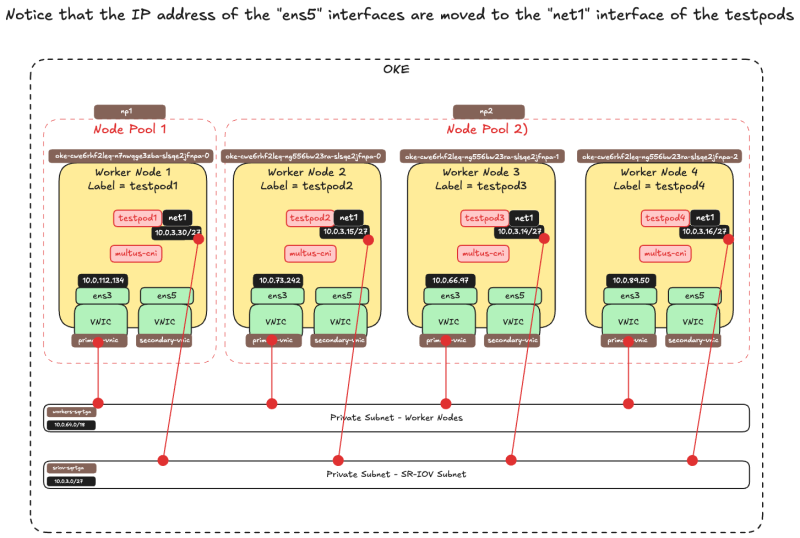
Now that the testpods net1 interfaces have an IP address, notice that this IP address used to be the IP address of the ens5 interface on the worker nodes.
This IP address is now moved from the ens5 worker node interface to the net1 testpod interface.
- SSH into the first worker node with the command
ssh -i id_rsa opc@10.0.112.134 - Get the IP addresses of all the interfaces with the command
ip a - Notice that the
ens5interface has been removed from the worker node.
[opc@o-sqrtga ~]$ ssh -i id_rsa opc@10.0.112.134
Activate the web console with: systemctl enable --now cockpit.socket

Last login: Wed Dec 18 20:42:19 2024 from 10.0.0.11
[opc@oke-cwe6rhf2leq-n7nwqge3zba-slsqe2jfnpa-0 ~]$ ip a
1: lo: <LOOPBACK,UP,LOWER_UP> mtu 65536 qdisc noqueue state UNKNOWN group default qlen 1000
    link/loopback 00:00:00:00:00:00 brd 00:00:00:00:00:00
    inet 127.0.0.1/8 scope host lo
       valid_lft forever preferred_lft forever
    inet6 ::1/128 scope host
       valid_lft forever preferred_lft forever
2: ens3: <BROADCAST,MULTICAST,UP,LOWER_UP> mtu 9000 qdisc mq state UP group default qlen 1000
    link/ether 02:00:17:00:59:58 brd ff:ff:ff:ff:ff:ff
    altname enp0s3
    inet 10.0.112.134/18 brd 10.0.127.255 scope global dynamic ens3
       valid_lft 82180sec preferred_lft 82180sec
    inet6 fe80::17ff:fe00:5958/64 scope link
       valid_lft forever preferred_lft forever
4: flannel.1: <BROADCAST,MULTICAST,UP,LOWER_UP> mtu 8950 qdisc noqueue state UNKNOWN group default
    link/ether 3a:b7:fb:e6:2e:cf brd ff:ff:ff:ff:ff:ff
    inet 10.244.1.0/32 scope global flannel.1
       valid_lft forever preferred_lft forever
    inet6 fe80::38b7:fbff:fee6:2ecf/64 scope link
       valid_lft forever preferred_lft forever
5: cni0: <BROADCAST,MULTICAST,UP,LOWER_UP> mtu 8950 qdisc noqueue state UP group default qlen 1000
    link/ether de:35:f5:51:85:5d brd ff:ff:ff:ff:ff:ff
    inet 10.244.1.1/25 brd 10.244.1.127 scope global cni0
       valid_lft forever preferred_lft forever
    inet6 fe80::dc35:f5ff:fe51:855d/64 scope link
       valid_lft forever preferred_lft forever
6: veth1cdaac17@if2: <BROADCAST,MULTICAST,UP,LOWER_UP> mtu 8950 qdisc noqueue master cni0 state UP group default
    link/ether 76:e2:92:ad:37:40 brd ff:ff:ff:ff:ff:ff link-netns 1935ba66-34cc-4468-8abb-f66add46d08b
    inet6 fe80::74e2:92ff:fead:3740/64 scope link
       valid_lft forever preferred_lft forever
7: vethbcd391ab@if2: <BROADCAST,MULTICAST,UP,LOWER_UP> mtu 8950 qdisc noqueue master cni0 state UP group default
    link/ether 9a:9a:0f:d6:48:17 brd ff:ff:ff:ff:ff:ff link-netns 3f02d5fd-596e-4b9f-8a35-35f2f946901b
    inet6 fe80::989a:fff:fed6:4817/64 scope link
       valid_lft forever preferred_lft forever
8: vethc15fa705@if2: <BROADCAST,MULTICAST,UP,LOWER_UP> mtu 8950 qdisc noqueue master cni0 state UP group default
    link/ether 3a:d2:c8:66:d1:0b brd ff:ff:ff:ff:ff:ff link-netns f581b7f2-cfa0-46eb-b0aa-37001a11116d
    inet6 fe80::38d2:c8ff:fe66:d10b/64 scope link
       valid_lft forever preferred_lft forever
9: vethc663e496@if2: <BROADCAST,MULTICAST,UP,LOWER_UP> mtu 8950 qdisc noqueue master cni0 state UP group default
    link/ether 7e:0b:bb:5d:49:8c brd ff:ff:ff:ff:ff:ff link-netns d3993135-0f2f-4b06-b16d-31d659f8230d
    inet6 fe80::7c0b:bbff:fe5d:498c/64 scope link
       valid_lft forever preferred_lft forever
[opc@oke-cwe6rhf2leq-n7nwqge3zba-slsqe2jfnpa-0 ~]$ exit
logout
Connection to 10.0.112.134 closed.
- SSH into the second worker node with the command
ssh -i id_rsa opc@10.0.66.97 - Get the IP addresses of all the interfaces with the command
ip a - Notice that the
ens5interface has been removed from the worker node.
[opc@o-sqrtga ~]$ ssh -i id_rsa opc@10.0.66.97
Activate the web console with: systemctl enable --now cockpit.socket

Last login: Wed Dec 18 19:47:55 2024 from 10.0.0.11
[opc@oke-cwe6rhf2leq-ng556bw23ra-slsqe2jfnpa-1 ~]$ ip a
1: lo: <LOOPBACK,UP,LOWER_UP> mtu 65536 qdisc noqueue state UNKNOWN group default qlen 1000
    link/loopback 00:00:00:00:00:00 brd 00:00:00:00:00:00
    inet 127.0.0.1/8 scope host lo
       valid_lft forever preferred_lft forever
    inet6 ::1/128 scope host
       valid_lft forever preferred_lft forever
2: ens3: <BROADCAST,MULTICAST,UP,LOWER_UP> mtu 9000 qdisc mq state UP group default qlen 1000
    link/ether 02:00:17:00:16:ca brd ff:ff:ff:ff:ff:ff
    altname enp0s3
    inet 10.0.66.97/18 brd 10.0.127.255 scope global dynamic ens3
       valid_lft 82502sec preferred_lft 82502sec
    inet6 fe80::17ff:fe00:16ca/64 scope link
       valid_lft forever preferred_lft forever
4: flannel.1: <BROADCAST,MULTICAST,UP,LOWER_UP> mtu 8950 qdisc noqueue state UNKNOWN group default
    link/ether 02:92:e7:f5:8e:29 brd ff:ff:ff:ff:ff:ff
    inet 10.244.1.128/32 scope global flannel.1
       valid_lft forever preferred_lft forever
    inet6 fe80::92:e7ff:fef5:8e29/64 scope link
       valid_lft forever preferred_lft forever
5: cni0: <BROADCAST,MULTICAST,UP,LOWER_UP> mtu 8950 qdisc noqueue state UP group default qlen 1000
    link/ether f6:08:06:e2:bc:9d brd ff:ff:ff:ff:ff:ff
    inet 10.244.1.129/25 brd 10.244.1.255 scope global cni0
       valid_lft forever preferred_lft forever
    inet6 fe80::f408:6ff:fee2:bc9d/64 scope link
       valid_lft forever preferred_lft forever
6: veth5db97290@if2: <BROADCAST,MULTICAST,UP,LOWER_UP> mtu 8950 qdisc noqueue master cni0 state UP group default
    link/ether c2:e0:b5:7e:ce:ed brd ff:ff:ff:ff:ff:ff link-netns 3682b5cd-9039-4931-aecc-b50d46dabaf1
    inet6 fe80::c0e0:b5ff:fe7e:ceed/64 scope link
       valid_lft forever preferred_lft forever
7: veth6fd818a5@if2: <BROADCAST,MULTICAST,UP,LOWER_UP> mtu 8950 qdisc noqueue master cni0 state UP group default
    link/ether 3e:a8:7d:84:d3:b9 brd ff:ff:ff:ff:ff:ff link-netns 08141d6b-5ec0-4f3f-a312-a00b30f82ade
    inet6 fe80::3ca8:7dff:fe84:d3b9/64 scope link
       valid_lft forever preferred_lft forever
8: veth26f6b686@if2: <BROADCAST,MULTICAST,UP,LOWER_UP> mtu 8950 qdisc noqueue master cni0 state UP group default
    link/ether ae:bf:36:ca:52:cf brd ff:ff:ff:ff:ff:ff link-netns f533714a-69be-4b20-be30-30ba71494f7a
    inet6 fe80::acbf:36ff:feca:52cf/64 scope link
       valid_lft forever preferred_lft forever
[opc@oke-cwe6rhf2leq-ng556bw23ra-slsqe2jfnpa-1 ~]$ exit
logout
Connection to 10.0.66.97 closed.
- SSH into the third worker node with the command
ssh -i id_rsa opc@10.0.73.242 - Get the IP addresses of all the interfaces with the command
ip a - Notice that the
ens5interface has been removed from the worker node.
[opc@o-sqrtga ~]$ ssh -i id_rsa opc@10.0.73.242
Activate the web console with: systemctl enable --now cockpit.socket

Last login: Wed Dec 18 20:08:31 2024 from 10.0.0.11
[opc@oke-cwe6rhf2leq-ng556bw23ra-slsqe2jfnpa-0 ~]$ ip a
1: lo: <LOOPBACK,UP,LOWER_UP> mtu 65536 qdisc noqueue state UNKNOWN group default qlen 1000
    link/loopback 00:00:00:00:00:00 brd 00:00:00:00:00:00
    inet 127.0.0.1/8 scope host lo
       valid_lft forever preferred_lft forever
    inet6 ::1/128 scope host
       valid_lft forever preferred_lft forever
2: ens3: <BROADCAST,MULTICAST,UP,LOWER_UP> mtu 9000 qdisc mq state UP group default qlen 1000
    link/ether 02:00:17:00:49:9c brd ff:ff:ff:ff:ff:ff
    altname enp0s3
    inet 10.0.73.242/18 brd 10.0.127.255 scope global dynamic ens3
       valid_lft 82733sec preferred_lft 82733sec
    inet6 fe80::17ff:fe00:499c/64 scope link
       valid_lft forever preferred_lft forever
4: flannel.1: <BROADCAST,MULTICAST,UP,LOWER_UP> mtu 8950 qdisc noqueue state UNKNOWN group default
    link/ether 9a:c7:1b:30:e8:9a brd ff:ff:ff:ff:ff:ff
    inet 10.244.0.0/32 scope global flannel.1
       valid_lft forever preferred_lft forever
    inet6 fe80::98c7:1bff:fe30:e89a/64 scope link
       valid_lft forever preferred_lft forever
5: cni0: <BROADCAST,MULTICAST,UP,LOWER_UP> mtu 8950 qdisc noqueue state UP group default qlen 1000
    link/ether 2a:2b:cb:fb:15:82 brd ff:ff:ff:ff:ff:ff
    inet 10.244.0.1/25 brd 10.244.0.127 scope global cni0
       valid_lft forever preferred_lft forever
    inet6 fe80::282b:cbff:fefb:1582/64 scope link
       valid_lft forever preferred_lft forever
6: veth06343057@if2: <BROADCAST,MULTICAST,UP,LOWER_UP> mtu 8950 qdisc noqueue master cni0 state UP group default
    link/ether ca:70:83:13:dc:ed brd ff:ff:ff:ff:ff:ff link-netns fb0f181f-7c3a-4fb6-8bf0-5a65d39486c1
    inet6 fe80::c870:83ff:fe13:dced/64 scope link
       valid_lft forever preferred_lft forever
7: veth8af17165@if2: <BROADCAST,MULTICAST,UP,LOWER_UP> mtu 8950 qdisc noqueue master cni0 state UP group default
    link/ether c6:a0:be:75:9b:d9 brd ff:ff:ff:ff:ff:ff link-netns c07346e6-33f5-4e80-ba5e-74f7487b5daa
    inet6 fe80::c4a0:beff:fe75:9bd9/64 scope link
       valid_lft forever preferred_lft forever
8: veth170b8774@if2: <BROADCAST,MULTICAST,UP,LOWER_UP> mtu 8950 qdisc noqueue master cni0 state UP group default
    link/ether e6:c9:42:60:8f:e7 brd ff:ff:ff:ff:ff:ff link-netns edef0c81-0477-43fa-b260-6b81626e7d87
    inet6 fe80::e4c9:42ff:fe60:8fe7/64 scope link
       valid_lft forever preferred_lft forever
[opc@oke-cwe6rhf2leq-ng556bw23ra-slsqe2jfnpa-0 ~]$ exit
logout
Connection to 10.0.73.242 closed.
- SSH into the fourth worker node with the command
ssh -i id_rsa opc@10.0.89.50 - Get the IP addresses of all the interfaces with the command
ip a - Notice that the
ens5interface has been removed from the worker node.
[opc@o-sqrtga ~]$ ssh -i id_rsa opc@10.0.89.50
Activate the web console with: systemctl enable --now cockpit.socket

Last login: Wed Dec 18 19:49:27 2024 from 10.0.0.11
[opc@oke-cwe6rhf2leq-ng556bw23ra-slsqe2jfnpa-2 ~]$ ip a
1: lo: <LOOPBACK,UP,LOWER_UP> mtu 65536 qdisc noqueue state UNKNOWN group default qlen 1000
    link/loopback 00:00:00:00:00:00 brd 00:00:00:00:00:00
    inet 127.0.0.1/8 scope host lo
       valid_lft forever preferred_lft forever
    inet6 ::1/128 scope host
       valid_lft forever preferred_lft forever
2: ens3: <BROADCAST,MULTICAST,UP,LOWER_UP> mtu 9000 qdisc mq state UP group default qlen 1000
    link/ether 02:00:17:00:ac:7c brd ff:ff:ff:ff:ff:ff
    altname enp0s3
    inet 10.0.89.50/18 brd 10.0.127.255 scope global dynamic ens3
       valid_lft 82976sec preferred_lft 82976sec
    inet6 fe80::17ff:fe00:ac7c/64 scope link
       valid_lft forever preferred_lft forever
4: flannel.1: <BROADCAST,MULTICAST,UP,LOWER_UP> mtu 8950 qdisc noqueue state UNKNOWN group default
    link/ether aa:31:9f:d0:b3:3c brd ff:ff:ff:ff:ff:ff
    inet 10.244.0.128/32 scope global flannel.1
       valid_lft forever preferred_lft forever
    inet6 fe80::a831:9fff:fed0:b33c/64 scope link
       valid_lft forever preferred_lft forever
5: cni0: <BROADCAST,MULTICAST,UP,LOWER_UP> mtu 8950 qdisc noqueue state UP group default qlen 1000
    link/ether b2:0d:c0:de:02:61 brd ff:ff:ff:ff:ff:ff
    inet 10.244.0.129/25 brd 10.244.0.255 scope global cni0
       valid_lft forever preferred_lft forever
    inet6 fe80::b00d:c0ff:fede:261/64 scope link
       valid_lft forever preferred_lft forever
6: vethb37e8987@if2: <BROADCAST,MULTICAST,UP,LOWER_UP> mtu 8950 qdisc noqueue master cni0 state UP group default
    link/ether 7a:93:1d:2a:33:8c brd ff:ff:ff:ff:ff:ff link-netns ab3262ca-4a80-4b02-a39f-4209d003f148
    inet6 fe80::7893:1dff:fe2a:338c/64 scope link
       valid_lft forever preferred_lft forever
7: veth73a651ce@if2: <BROADCAST,MULTICAST,UP,LOWER_UP> mtu 8950 qdisc noqueue master cni0 state UP group default
    link/ether ae:e4:97:89:ba:6e brd ff:ff:ff:ff:ff:ff link-netns 9307bfbd-8165-46bf-916c-e1180b6cbd83
    inet6 fe80::ace4:97ff:fe89:ba6e/64 scope link
       valid_lft forever preferred_lft forever
8: veth42c3a604@if2: <BROADCAST,MULTICAST,UP,LOWER_UP> mtu 8950 qdisc noqueue master cni0 state UP group default
    link/ether f2:e6:ba:72:8f:b2 brd ff:ff:ff:ff:ff:ff link-netns a7eb561c-8182-49b2-9e43-7c52845620a7
    inet6 fe80::f0e6:baff:fe72:8fb2/64 scope link
       valid_lft forever preferred_lft forever
[opc@oke-cwe6rhf2leq-ng556bw23ra-slsqe2jfnpa-2 ~]$ exit
logout
Connection to 10.0.89.50 closed.
[opc@o-sqrtga ~]$
The picture below is a visual overview of what we have configured so far.
STEP 08 - Do some ping tests between multiple PODs
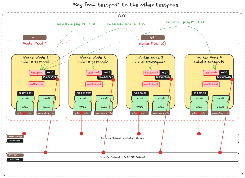
Now that all the PODs have an IP address from the OCI Subnet where the SR-IOV-enabled VNICS are attached we can do some ping tests to verify if the network connectivity is working properly.
The table below provides the commands to connect to the test pods from the Kubernetes Operator. We need this to "exec" into each pod to either perform a ping test or to look at the route table.
| ens3 | net1 | name | pod name | command |
|---|---|---|---|---|
| 10.0.112.134 | 10.0.3.30/27 | sriov-vnic-1 | testpod1 | kubectl exec -it testpod1 -- /bin/bash
|
| 10.0.66.97 | 10.0.3.15/27 | sriov-vnic-2 | testpod2 | kubectl exec -it testpod2 -- /bin/bash
|
| 10.0.73.242 | 10.0.3.14/27 | sriov-vnic-3 | testpod3 | kubectl exec -it testpod3 -- /bin/bash
|
| 10.0.89.50 | 10.0.3.16/27 | sriov-vnic-4 | testpod4 | kubectl exec -it testpod4 -- /bin/bash
|
* We can also use the following command to look at the routing table directly from the Kubernetes Operator terminal for testpod1: kubectl exec -it testpod1 -- route -n
- Notice that the routing table of
testpod1has a default gateway foreth0and fornet1which is our SR-IOV-enabled interface.
[opc@o-sqrtga ~]$ kubectl exec -it testpod1 -- route -n
Kernel IP routing table
Destination     Gateway         Genmask         Flags Metric Ref    Use Iface
0.0.0.0         10.244.0.129    0.0.0.0         UG    0      0        0 eth0
10.0.3.0        0.0.0.0         255.255.255.224 U     0      0        0 net1
10.0.3.0        0.0.0.0         255.255.255.224 U     0      0        0 net1
10.244.0.0      10.244.0.129    255.255.0.0     UG    0      0        0 eth0
10.244.0.128    0.0.0.0         255.255.255.128 U     0      0        0 eth0
- Use the following command to look at the routing table directly from the Kubernetes Operator terminal for
testpod2:kubectl exec -it testpod2 -- route -n - Notice that the routing table of
testpod2has a default gateway foreth0and fornet1which is our SR-IOV-enabled interface.
[opc@o-sqrtga ~]$ kubectl exec -it testpod2 -- route -n
Kernel IP routing table
Destination     Gateway         Genmask         Flags Metric Ref    Use Iface
0.0.0.0         10.244.1.129    0.0.0.0         UG    0      0        0 eth0
10.0.3.0        0.0.0.0         255.255.255.224 U     0      0        0 net1
10.0.3.0        0.0.0.0         255.255.255.224 U     0      0        0 net1
10.244.0.0      10.244.1.129    255.255.0.0     UG    0      0        0 eth0
10.244.1.128    0.0.0.0         255.255.255.128 U     0      0        0 eth0
- Use the following command to look at the routing table directly from the Kubernetes Operator terminal for
testpod3:kubectl exec -it testpod3 -- route -n - Notice that the routing table of
testpod3has a default gateway foreth0and fornet1which is our SR-IOV-enabled interface.
[opc@o-sqrtga ~]$ kubectl exec -it testpod3 -- route -n
Kernel IP routing table
Destination     Gateway         Genmask         Flags Metric Ref    Use Iface
0.0.0.0         10.244.0.1      0.0.0.0         UG    0      0        0 eth0
10.0.3.0        0.0.0.0         255.255.255.224 U     0      0        0 net1
10.0.3.0        0.0.0.0         255.255.255.224 U     0      0        0 net1
10.244.0.0      0.0.0.0         255.255.255.128 U     0      0        0 eth0
10.244.0.0      10.244.0.1      255.255.0.0     UG    0      0        0 eth0
- Use the following command to look at the routing table directly from the Kubernetes Operator terminal for
testpod4:kubectl exec -it testpod4 -- route -n - Notice that the routing table of
testpod4has a default gateway foreth0and fornet1which is our SR-IOV-enabled interface.
[opc@o-sqrtga ~]$ kubectl exec -it testpod4 -- route -n
Kernel IP routing table
Destination     Gateway         Genmask         Flags Metric Ref    Use Iface
0.0.0.0         10.244.1.1      0.0.0.0         UG    0      0        0 eth0
10.0.3.0        0.0.0.0         255.255.255.224 U     0      0        0 net1
10.0.3.0        0.0.0.0         255.255.255.224 U     0      0        0 net1
10.244.0.0      10.244.1.1      255.255.0.0     UG    0      0        0 eth0
10.244.1.0      0.0.0.0         255.255.255.128 U     0      0        0 eth0
[opc@o-sqrtga ~]$
To perform the ping test from the Kubernetes Operator directly from the testpods we need the ping command. In the table below I have provided all the ping commands for all testpods.
The command will ping from a particular testpod to all the other testpods including its net1 IP address.
| Source pod name | command |
|---|---|
| testpod1 | kubectl exec -it testpod1 -- ping -I net1 10.0.3.30 -c 4kubectl exec -it testpod1 -- ping -I net1 10.0.3.15 -c 4kubectl exec -it testpod1 -- ping -I net1 10.0.3.14 -c 4kubectl exec -it testpod1 -- ping -I net1 10.0.3.16 -c 4
|
| testpod2 | kubectl exec -it testpod2 -- ping -I net1 10.0.3.15 -c 4kubectl exec -it testpod2 -- ping -I net1 10.0.3.30 -c 4kubectl exec -it testpod2 -- ping -I net1 10.0.3.14 -c 4kubectl exec -it testpod2 -- ping -I net1 10.0.3.16 -c 4
|
| testpod3 | kubectl exec -it testpod3 -- ping -I net1 10.0.3.14 -c 4kubectl exec -it testpod3 -- ping -I net1 10.0.3.30 -c 4kubectl exec -it testpod3 -- ping -I net1 10.0.3.15 -c 4kubectl exec -it testpod3 -- ping -I net1 10.0.3.16 -c 4
|
| testpod4 | kubectl exec -it testpod4 -- ping -I net1 10.0.3.16 -c 4kubectl exec -it testpod4 -- ping -I net1 10.0.3.30 -c 4kubectl exec -it testpod4 -- ping -I net1 10.0.3.15 -c 4kubectl exec -it testpod4 -- ping -I net1 10.0.3.14 -c 4
|
Below you will find an example where I am using testpod1 to ping all the other testpod net1 IP addresses.
- Use the command
kubectl exec -it testpod1 -- ping -I net1 10.0.3.30 -c 4to ping fromtestpod1totestpod1. - Notice that the ping has
4 packets transmitted, 4 received, 0% packet loss. So the ping is successful.
[opc@o-sqrtga ~]$ kubectl exec -it testpod1 -- ping -I net1 10.0.3.30 -c 4
PING 10.0.3.30 (10.0.3.30) from 10.0.3.30 net1: 56(84) bytes of data.
64 bytes from 10.0.3.30: icmp_seq=1 ttl=64 time=0.043 ms
64 bytes from 10.0.3.30: icmp_seq=2 ttl=64 time=0.024 ms
64 bytes from 10.0.3.30: icmp_seq=3 ttl=64 time=0.037 ms
64 bytes from 10.0.3.30: icmp_seq=4 ttl=64 time=0.026 ms

--- 10.0.3.30 ping statistics ---
4 packets transmitted, 4 received, 0% packet loss, time 3087ms
rtt min/avg/max/mdev = 0.024/0.032/0.043/0.009 ms
- Use the command
kubectl exec -it testpod1 -- ping -I net1 10.0.3.15 -c 4to ping fromtestpod1totestpod2. - Notice that the ping has
4 packets transmitted, 4 received, 0% packet loss. So the ping is successful.
[opc@o-sqrtga ~]$ kubectl exec -it testpod1 -- ping -I net1 10.0.3.15 -c 4
PING 10.0.3.15 (10.0.3.15) from 10.0.3.30 net1: 56(84) bytes of data.
64 bytes from 10.0.3.15: icmp_seq=1 ttl=64 time=0.383 ms
64 bytes from 10.0.3.15: icmp_seq=2 ttl=64 time=0.113 ms
64 bytes from 10.0.3.15: icmp_seq=3 ttl=64 time=0.114 ms
64 bytes from 10.0.3.15: icmp_seq=4 ttl=64 time=0.101 ms

--- 10.0.3.15 ping statistics ---
4 packets transmitted, 4 received, 0% packet loss, time 3109ms
rtt min/avg/max/mdev = 0.101/0.177/0.383/0.119 ms
- Use the command
kubectl exec -it testpod1 -- ping -I net1 10.0.3.14 -c 4to ping fromtestpod1totestpod3. - Notice that the ping has
4 packets transmitted, 4 received, 0% packet loss. So the ping is successful.
[opc@o-sqrtga ~]$ kubectl exec -it testpod1 -- ping -I net1 10.0.3.14 -c 4
PING 10.0.3.14 (10.0.3.14) from 10.0.3.30 net1: 56(84) bytes of data.
64 bytes from 10.0.3.14: icmp_seq=1 ttl=64 time=0.399 ms
64 bytes from 10.0.3.14: icmp_seq=2 ttl=64 time=0.100 ms
64 bytes from 10.0.3.14: icmp_seq=3 ttl=64 time=0.130 ms
64 bytes from 10.0.3.14: icmp_seq=4 ttl=64 time=0.124 ms

--- 10.0.3.14 ping statistics ---
4 packets transmitted, 4 received, 0% packet loss, time 3057ms
rtt min/avg/max/mdev = 0.100/0.188/0.399/0.122 ms
- Use the command
kubectl exec -it testpod1 -- ping -I net1 10.0.3.16 -c 4to ping fromtestpod1totestpod4. - Notice that the ping has
4 packets transmitted, 4 received, 0% packet loss. So the ping is successful.
[opc@o-sqrtga ~]$ kubectl exec -it testpod1 -- ping -I net1 10.0.3.16 -c 4
PING 10.0.3.16 (10.0.3.16) from 10.0.3.30 net1: 56(84) bytes of data.
64 bytes from 10.0.3.16: icmp_seq=1 ttl=64 time=0.369 ms
64 bytes from 10.0.3.16: icmp_seq=2 ttl=64 time=0.154 ms
64 bytes from 10.0.3.16: icmp_seq=3 ttl=64 time=0.155 ms
64 bytes from 10.0.3.16: icmp_seq=4 ttl=64 time=0.163 ms

--- 10.0.3.16 ping statistics ---
4 packets transmitted, 4 received, 0% packet loss, time 3110ms
rtt min/avg/max/mdev = 0.154/0.210/0.369/0.092 ms
[opc@o-sqrtga ~]$
I have not included all the other ping outputs for all the other testpods, but you get the idea.
The picture below is a visual overview of what we have configured so far.
STEP 09 - OPTIONAL - Deploy PODs with multiple interfaces
Right now we have only prepared one VNIC (that happens to support SR-IOV) and moved this VNIC into a POD. We did this for four different test pods. Now what if we would like to add/move more VNICs into a particular pod?
- Repeat the steps to create a new OCI Subnet.
- Repeat the steps to create a new VNIC + assign the IP address.
- Create a new NetworkAttachmentDefinitions.
- Update the testpod YAML file by adding new annotations.
Below you will find an example where I created an additional Subnet + VNIC + assigned the IP address + NetworkAttachmentDefinition and added this to the pod creation YAML file for testpod1.
- This is the NetworkAttachmentDefinition for a new interface
ens6with an IP address10.0.4.29/27on the network10.0.4.0/27. - Note that this is another NetworkAttachmentDefinition than we had before for the interface
ens5with an IP address10.0.3.30/27on the network10.0.3.0/27.
sriov-vnic-2-new.yaml
apiVersion: "k8s.cni.cncf.io/v1"
kind: NetworkAttachmentDefinition
metadata:
  name: sriov-vnic-2-new
spec:
  config: '{
        "cniVersion": "0.3.1",
        "type": "host-device",
        "device": "ens6",
        "ipam": {
                "type": "static",
                "addresses": [
                    {
                        "address": "10.0.4.29/27",
                        "gateway": "0.0.0.0"
                    }
                ],
                "routes": [
                    { "dst": "10.0.4.0/27", "gw": "0.0.0.0" }
                ]
            }
          }'
- This is the (updated) YAML file for
testpod1. - Notice the additional line in the
annotationswhere the new NetworkAttachmentDefinitionsriov-vnic-2-newis referenced.
sudo nano testpod1-v3.yaml

apiVersion: v1
kind: Pod
metadata:
name: testpod1
annotations:
	k8s.v1.cni.cncf.io/networks: sriov-vnic-1
	k8s.v1.cni.cncf.io/networks: sriov-vnic-2-new
spec:
affinity:
	nodeAffinity:
	requiredDuringSchedulingIgnoredDuringExecution:
		nodeSelectorTerms:
		- matchExpressions:
		- key: node_type
			operator: In
			values:
			- testpod1
containers:
- name: appcntr1
	image: centos/tools
	imagePullPolicy: IfNotPresent
	command: [ "/bin/bash", "-c", "--" ]
	args: [ "while true; do sleep 300000; done;" ]
STEP 10 - Remove all POD deployments and NetworkAttachmentDefinitions
If you want to start over or want to clean up the containers with the NetworkAttachmentDefinitions you can execute the command below.
- Get all the pods with the command
kubectl get pod.
[opc@o-sqrtga ~]$ kubectl get pod
NAME                       READY   STATUS    RESTARTS   AGE
my-nginx-576c6b7b6-6fn6f   1/1     Running   3          105d
my-nginx-576c6b7b6-k9wwc   1/1     Running   3          105d
my-nginx-576c6b7b6-z8xkd   1/1     Running   6          105d
mysql-6d7f5d5944-dlm78     1/1     Running   12         100d
testpod1                   1/1     Running   0          64d
testpod2                   1/1     Running   0          64d
testpod3                   1/1     Running   0          64d
testpod4                   1/1     Running   0          64d
[opc@o-sqrtga ~]$
- Delete the test pods with the commands below:
kubectl delete -f testpod1-v2.yaml

kubectl delete -f testpod2-v2.yaml

kubectl delete -f testpod3-v2.yaml

kubectl delete -f testpod4-v2.yaml
- Get all the NetworkAttachmentDefinitions with the command
kubectl get network-attachment-definitions.k8s.cni.cncf.io.
[opc@o-sqrtga ~]$ kubectl get network-attachment-definitions.k8s.cni.cncf.io
NAME           AGE
sriov-vnic-1   64d
sriov-vnic-2   64d
sriov-vnic-3   64d
sriov-vnic-4   64d
[opc@o-sqrtga ~]$
- Delete the NetworkAttachmentDefinitions with the commands below:
kubectl delete networkattachmentdefinition.k8s.cni.cncf.io/sriov-vnic-1

kubectl delete networkattachmentdefinition.k8s.cni.cncf.io/sriov-vnic-2

kubectl delete networkattachmentdefinition.k8s.cni.cncf.io/sriov-vnic-3

kubectl delete networkattachmentdefinition.k8s.cni.cncf.io/sriov-vnic-4
