Add LB and WAF to a Hub to an Hub and Spoke VCN Routing architecture
This tutorial will guide you through the steps necessary to deploy and configure a load balancer with a Web Application Firewall (WAF) in OCI, highlighting how this will operate in a Hub and Spoke VCN Routing environment.
This tutorial will use the previously written tutorials below as its main foundation:
- [Deploy a Windows Instance in Oracle Cloud Infrastructure]
- [Install a pfSense Firewall in Oracle Cloud Infrastructure]
- [Route Hub and Spoke VCN with pfSense Firewall in the Hub VCN]
- [Connect On-premises to OCI using an IPSec VPN with Hub and Spoke VCN Routing Architecture]
Please make sure you go through the tutorials above first if you want to recreate the content in this tutorial.
The Steps
- STEP 01: Review the current Hub and Spoke Network Architecture
- STEP 02: Configure Routing in the Hub and Spoke Network Architecture between the WAF/LB the Hub Firewall and the Spoke Back-Ends.
- STEP 03: Install a web server on the back-end servers
- STEP 04: Create or modify a web page on the back-end servers
- STEP 05: Install an OCI Load Balancer
- STEP 06: Install/Configure an OCI Web Application Firewall
- STEP 07: Test the WAF/LB connectivity and WAF Security.
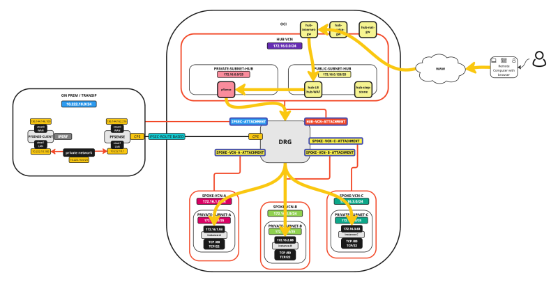
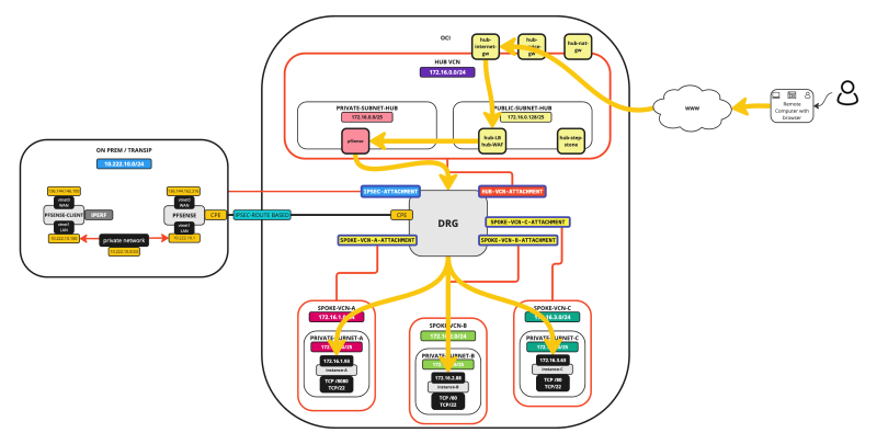
The traffic flows are illustrated in the pictures below.
External to Spoke connectivity using the LB + WAF
STEP 01 - Review the current Hub and Spoke Network Architecture
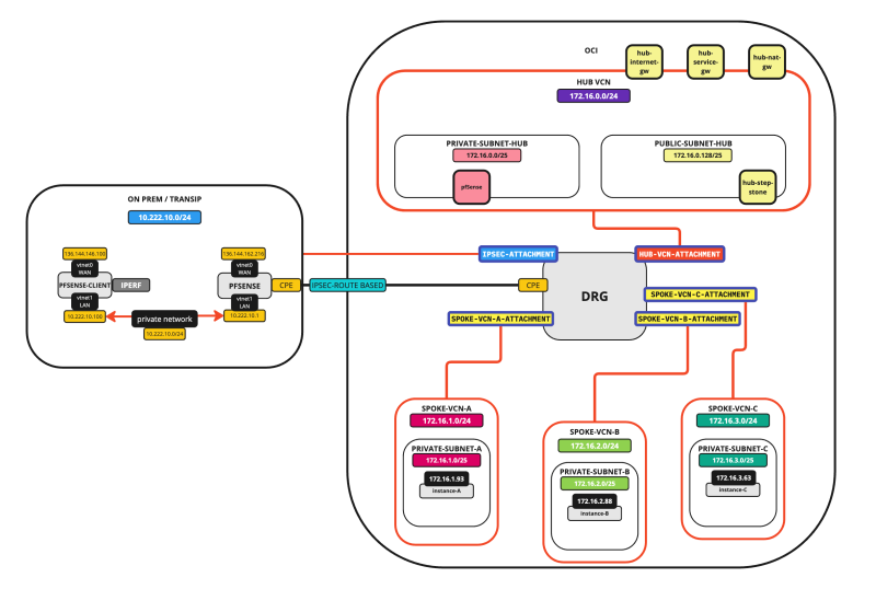
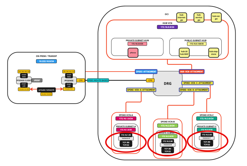
Our starting point for this tutorial will be that we will have:
- 1 x Hub VCN (with a firewall, internet gateway, NAT Gateway, and a Service Gateway)
- 3 x Spoke VCNs
- 1 x ON-PREM attached with an IPSEC VPN Connection
In the Hub VCN, we have a Windows Stepstone Instance that we can use to connect to the Spoke Instances. Each spoke will have one Instance that will be configured as a web server these instances can be used as endpoints for the load balance that we will deploy in this tutorial.
The picture below illustrates the starting point.
STEP 02 - Configure Routing in the Hub and Spoke Network Architecture between the WAF and LB the Hub Firewall and the Spoke Back-Ends
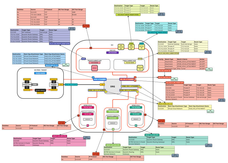
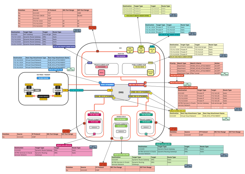
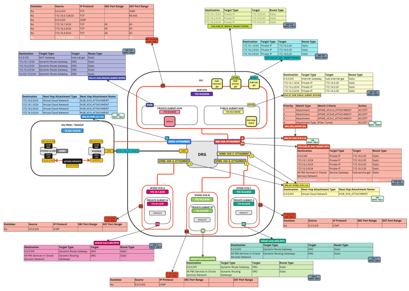
The picture below illustrates the current Hub and Spoke Network Architecture with all the Security lists and Routing tables shown in the picture.
Before we add the Load balancer we want to make sure that traffic that coming FROM the Load Balancer (subnet) is routed TO the Hub Firewall so that the traffic can be inspected on the Hub Firewall before it sends the traffic to the Spoke Instances. While we already have a default routing rule doing this, it is still best practice to add this rule in to call it out explicitly as we did with the other networks as well.
To add in the routing rule:
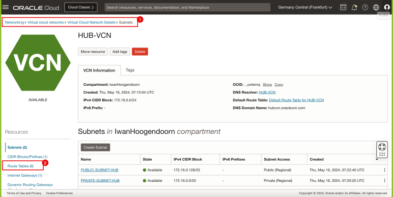
- Browse to Networking > Virtual Cloud networks > Virtual Cloud network details.
- Click on Route Tables.
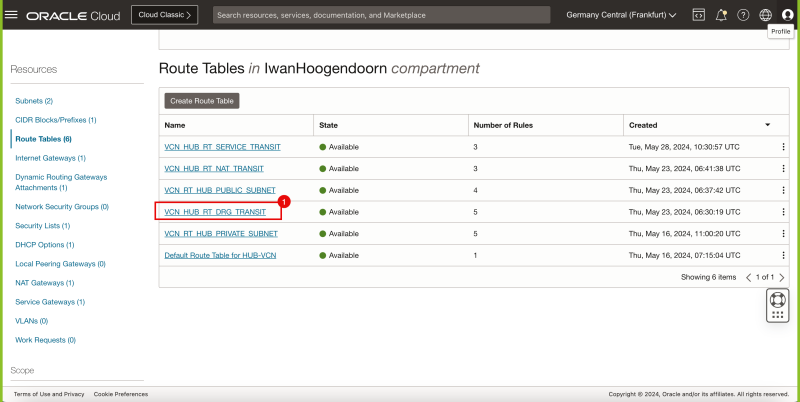
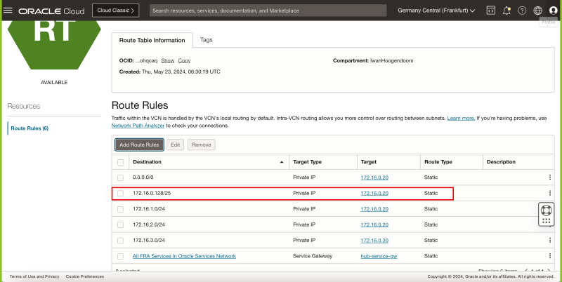
- Select the VCN_HUB_RT_DRG_TRANSIT route table.
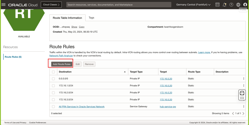
- Click on the Add Route Rules button.
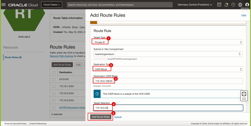
- Select Private IP as the target type.
- Specify CIDR Block as the Destination Type.
- Type in 0.0.0.0/0 for the Destination CIDR Block.
- Type in 172.16.0.20 for the Target Selection (This is the IP address of our pfSense Firewall).
- Click on the Add Route Rules button.
- Notice that the 172.16.0.128/25 route is now added to the VCN_HUB_RT_DRG_TRANSIT route table.
The picture below illustrates the current Hub and Spoke Network Architecture with all the Security lists and Routing tables (including the update we just made) shown in the picture.
STEP 03 - Install a web server on the back-end servers
Next, we are going to install an NGINX webserver on all the Instances in the Spoke VCNs. In [this tutorial (on step 6)]I explain how you install an NGINX Webserver on an Oracle Linux Instance.
STEP 04 - Create or modify a web page on the back-end servers
By default, each web server will be configured with a default web page. To track where our Load Balancer redirects the traffic to it is good practice to change something on the webpage so you know what server is hit.
We can do this by changing the content of the default NGINX index.html file.
sudo nano /usr/share/nginx/html/index.html
For Instance-A change the header to something like this:
<h1>Welcome to nginx! This is INSTANCE-A</h1>
For Instance-B change the header to something like this:
<h1>Welcome to nginx! This is INSTANCE-B</h1>
For Instance-C change the header to something like this:
<h1>Welcome to nginx! This is INSTANCE-C</h1>
Make sure you save the index.html files after changing them.
STEP 05 - Install an OCI Load Balancer
Before we create the Load Balancer (LB) we first need to ALLOW port 80 INGRESS on the Hub VCN Security list. All the traffic (including the traffic that is going from the Load Balancer in the Public Subnet of the Hub VCN) is routed to the HUB Firewall. The instances that the Load Balancer is going to use end-points are listening on port TCP/80. For this reason, we also need to allow port TCP/80 Ingress on the Hub VNC so that the Private subnet (in the Hub VCN) where the traffic is routed also allows the communication towards the Spoke VCNs.
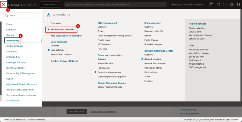
- Click on the hamburger menu in the upper left corner of the OCI console.
- Click on Networking.
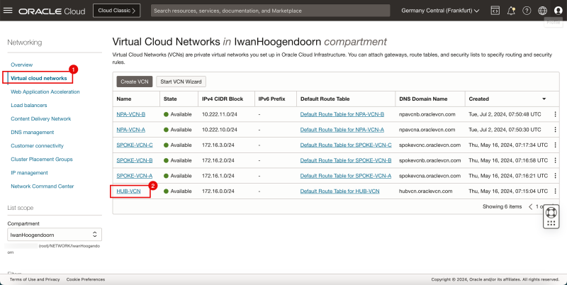
- Click on Virtual cloud networks.
- Make sure you are in the Virtual cloud network section.
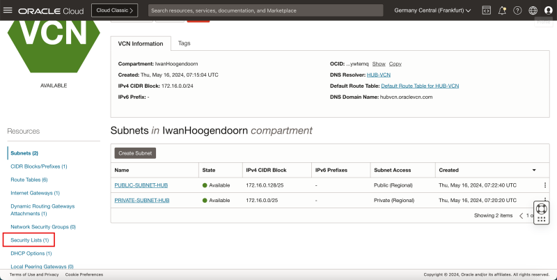
- Click on the HUB-VCN VCN.
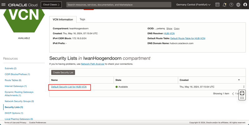
- Click on Security Lists.
- Click on the Default Security List for HUB-VCN.
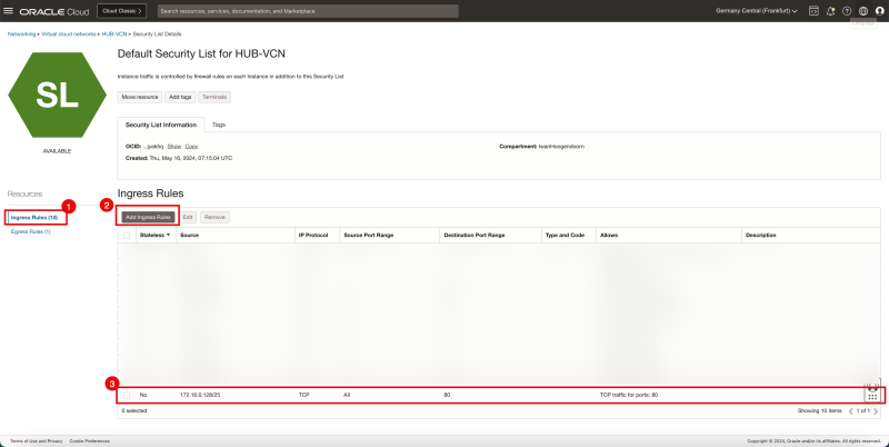
- Make sure you are in the Ingress section.
- Click on the Add Ingress Rules button.
- Add in a Security Rule that TCP/80 is allowed from the source 172.16.0.128/25 to ALL destinations.
We are using the Default Security List that is applied to the HUB-VCN and therefore applied to all separate Subnets inside this HUB-VCN.
This also means that traffic going from the Public Subnet towards the Private Subnet inside the HUB-VCN is also subject to this Default Security List as the SAME Default Security List is applied to BOTH subnets.
For this reason we are allowing port TCP/80 Ingress because if we do not do this the Load Balancer is not able to communicate with the back-end servers as all the traffic is sent from the Public Subnet to the Private Subnet because we are using a Hub-and-Spoke architecture with a Firewall inside the Private Subnet of the HUB-VCN.
Below you will see a visual representation of what you have created so far with the security rule added.
- Now let's create the Load Balancer (LB).
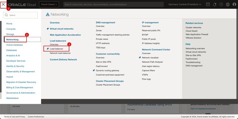
- Click on the hamburger menu in the upper left corner of the OCI console.
- Click on Networking.
- Click on Load Balancer.
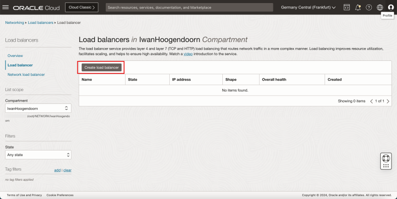
- Click on the Create load balancer button.
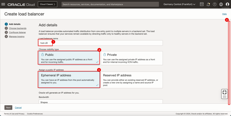
- Provide a name for the Load Balancer.
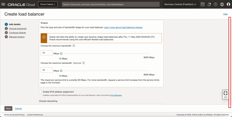
- Select Public for the visibility type.
- Assign an Ephemeral IP address.
- Scroll down.
- Leave everything default, and scroll down.
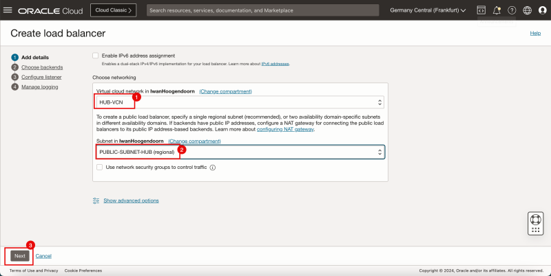
- Select the VCN where you want to attach the Load Balancer.
- Select the Subnet where you want to attach the Load Balancer.
- Click on the Next button.
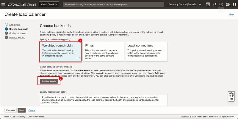
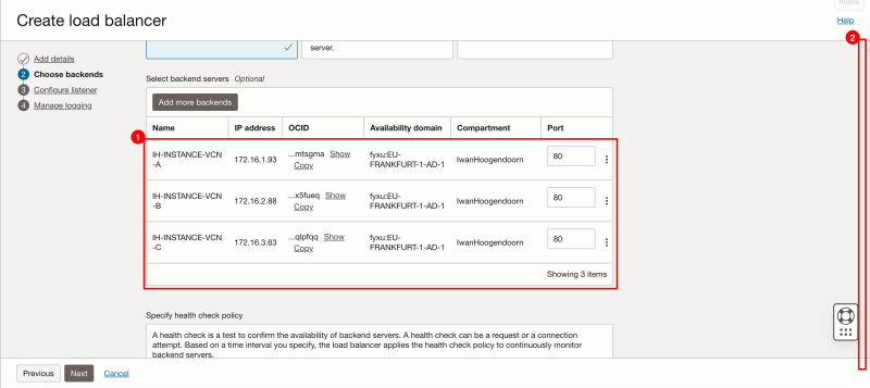
- Select Weighted Rond Robin as the load balancing policy.
- Click on the Add backends button.
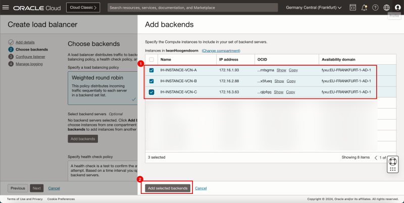
- Select all the backends of the instances (in the Spoke VCNs).
- Click on the Add backends button.
- Review the backends, and change the port if necessary, in my case all my back-end Instances listen to port 80.
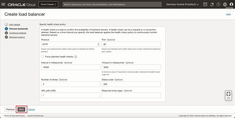
- Scroll down.
- Leave the Health Check Policy default, and click on the Next button.
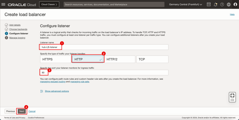
- Provide a name for the Listener.
- Specify the type of traffic to be HTTP for the listener.
- Specify a listener port to be 80.
- Click on the Next button.
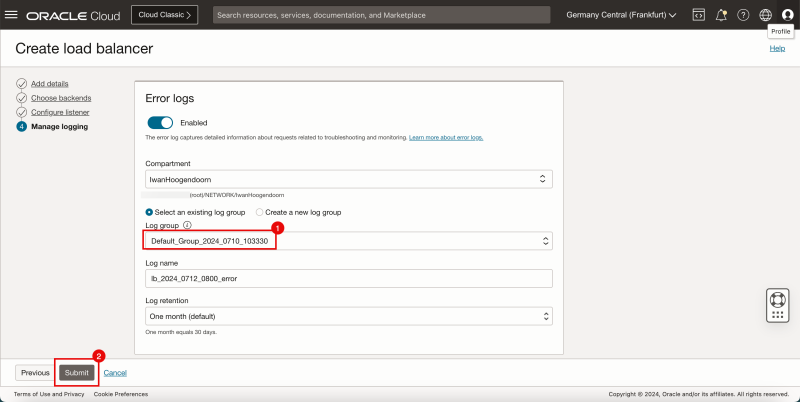
- Select a Log group.
- Click on the Submit button.
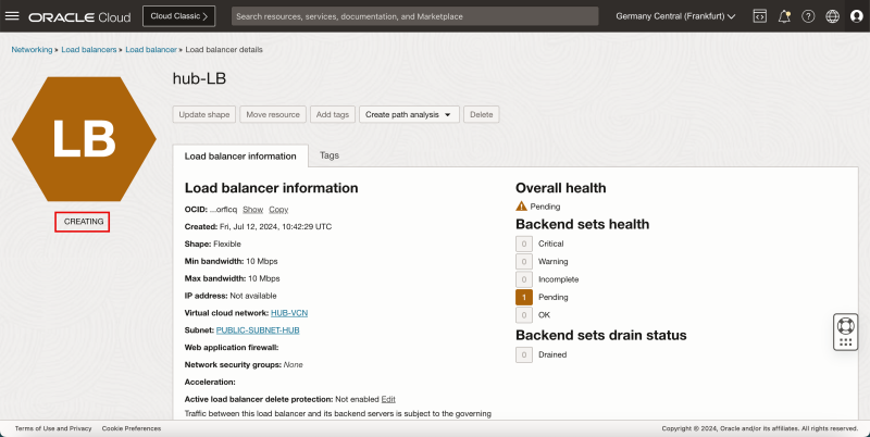
- Notice that the Load Balancer status is set to CREATING.
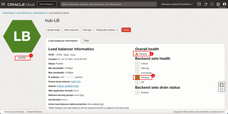
- Notice the Load Balancer status will change from CREATING to ACTIVE.
- Notice that the Overall health is still pending.
- Notice that the Backend sets health is still pending.
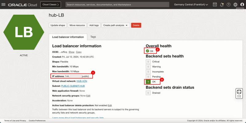
- Make a note of the PUBLIC IP address of the Load Balancer.
- Notice that the Overall health is now OK (it may take a minute to change).
- Notice that the Backend sets health is now OK (it may take a minute to change).
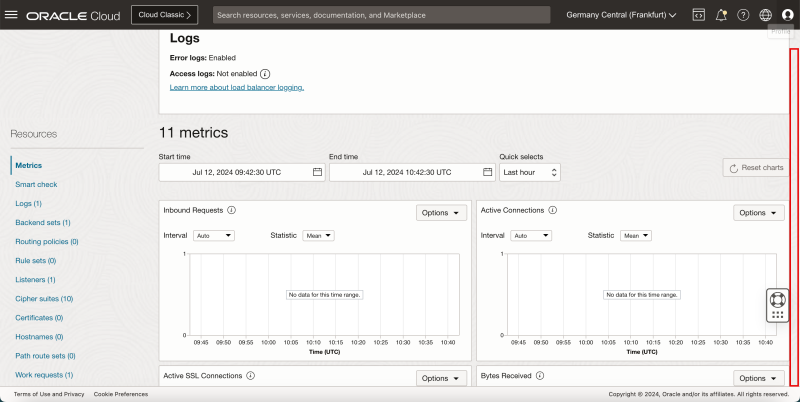
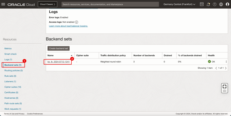
- Scroll down to take a closer look at the backend set.
- Click on Backend Sets.
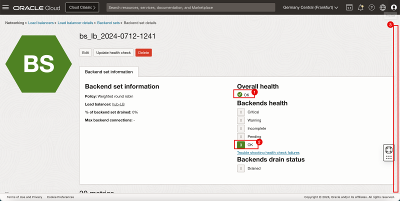
- Click on the only Backend set available.
- Notice that the Overall health is now OK.
- Notice that the Backend sets health is now OK.
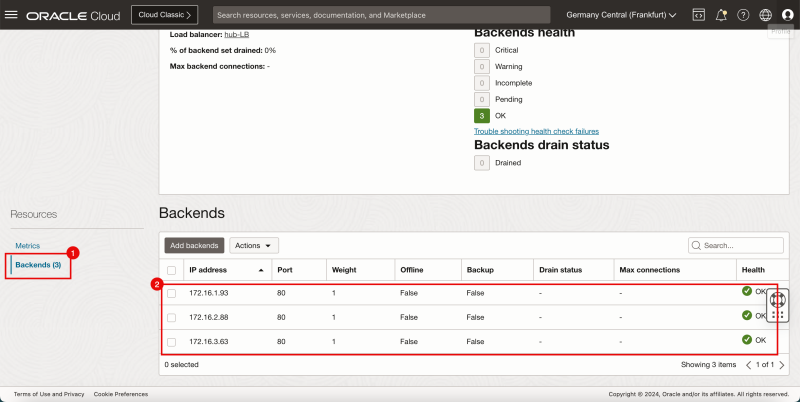
- Scroll down.
- Click on Backends.
- Notice the backends in the Backend set.
- Open a new browser.
- Type/Paste in the PUBLIC IP address of the Load Balancer.
- Notice that the Load Balancer redirects the traffic to the Instance in the Spoke VCN B.
- Refresh the page.
- Notice that the Load Balancer now redirects the traffic to the Instance in the Spoke VCN C.
- Refresh the page again.
- Notice that the Load Balancer now redirects the traffic to the Instance in the Spoke VCN B again.
- Refresh the page again.
- Notice that the Load Balancer now redirects the traffic to the Instance in the Spoke VCN A.
- Below you will see a visual representation of what you have created so far and how the traffic is flowing.
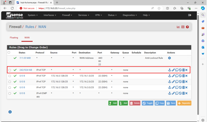
- Make sure that the HUB Firewall is allowing Port TCP/80 from the Load Balancer to the Backend servers.
- In my case, I just allowed ALL traffic in the HUB Firewall for testing purposes.
STEP 06 - Install and Configure an OCI Web Application Firewall
- Now that we have configured the Load Balancer we are ready to configure the Web Application Firewall.
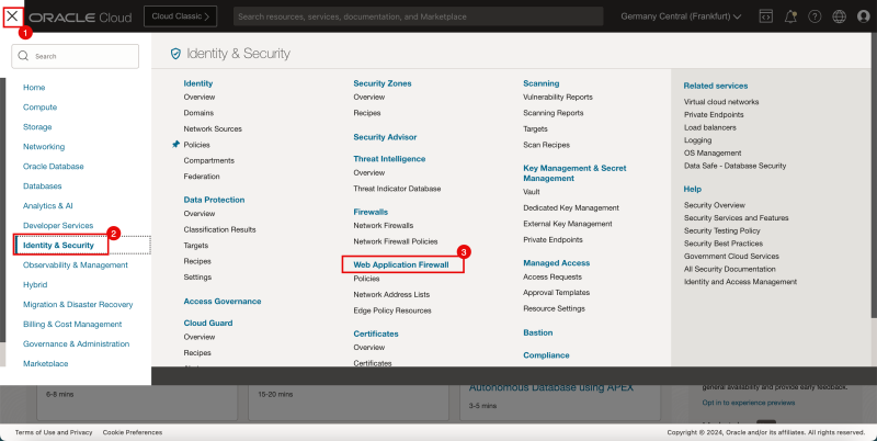
- Click on the hamburger menu in the upper left corner of the OCI console.
- Click on Identity & Security.
- Click on Web Application Firewall.
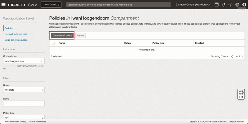
- Click on the Create WAF Policy button.
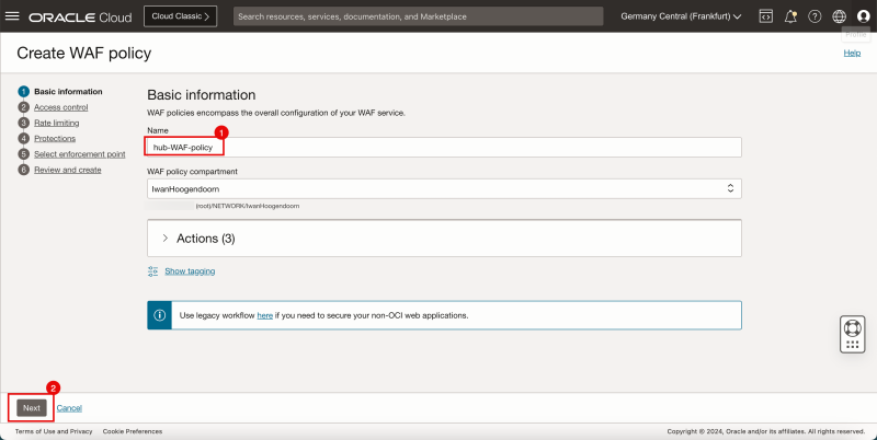
- Provide a name for the WAF Policy.
- Click on the Next button.
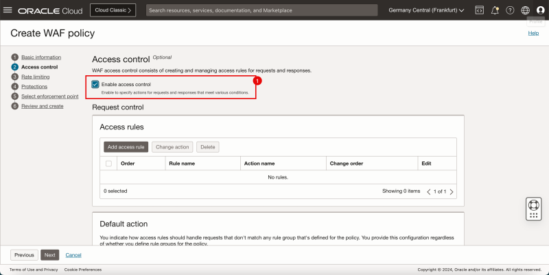
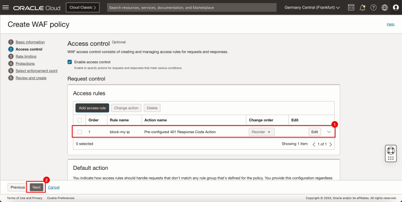
- Make sure that Enable access control is enabled.
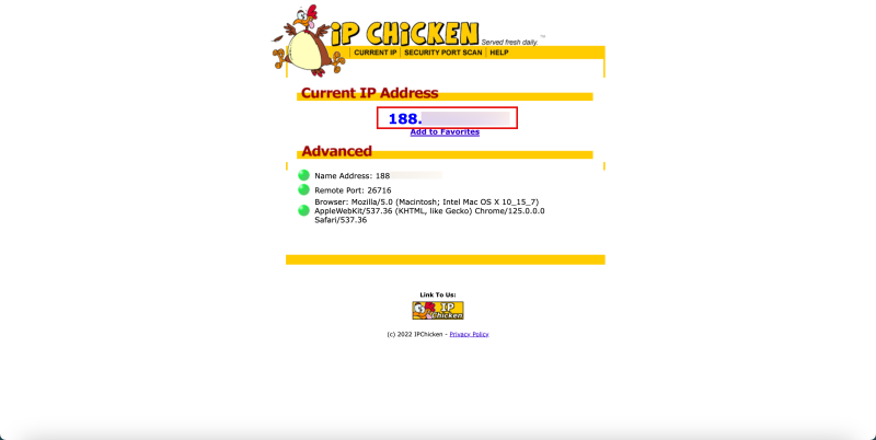
- Use a website that is capable of retrieving your ISP IP address.
- This is required to configure your access control in the Web Application Firewall.
- I am using www.ipchicken.com to retrieve my ISP IP address.
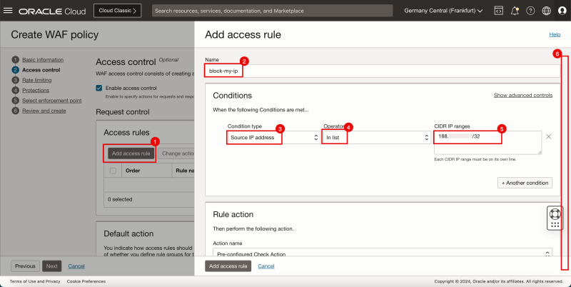
- Click on the Add access rule button.
- # Provide a name for the access rule.
- For the Condition Type select Source IP address.
- For the Operator select In list.
- For the CIDR IP ranges specify the IP address of your own ISP.
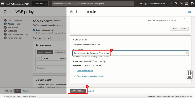
- Scroll down.
- For the rule action specify the action name and select Pre-configured 401 Response Code Action.
- Click on the Add access rule button.
- Notice that the access rule has been added.
- Click on the Next button.
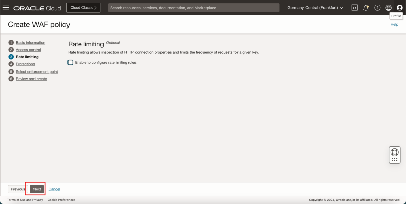
- Click on the Next button.
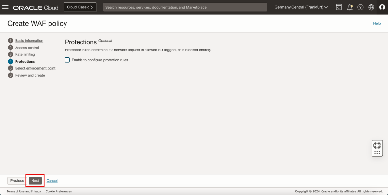
- Click on the Next button.
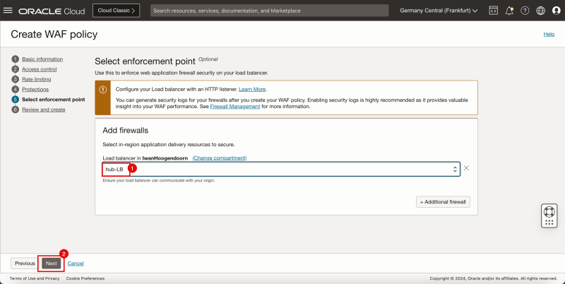
- Select the Load Balancer that you want to configure the WAF Policy on (use the Load Balancer we created in the previous step).
- Click on the Next button.
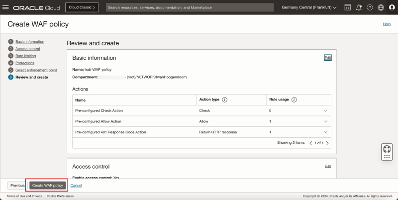
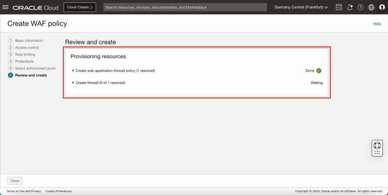
- Click on the Create WAF policy button.
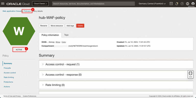
- Notice that the WAF Policy is created.
- Notice that the status of the WAF Policy is ACTIVE.
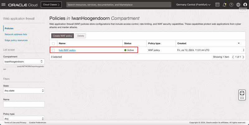
- Click on the Policies breadcrumbs menu to return to the WAF Policies page.
- Notice the WAF Policy that we just configured.
STEP 07 - Test the WAF and LB connectivity and WAF Security
- Go back to the browser we used earlier and refresh the page.
- If you closed it just type/paste in the PUBLIC IP address of the Load Balancer again.
- Notice that the web servers can no longer be accessed because we have blocked them with the WAF Policy.
Conclusion
In this article, we have configured a Load Balancer with a WAF policy in a Hub and Spoke Network Architecture. We Configured the web servers in a way that we could track how the load balancer is sending the traffic.
